Project 1 (Mini Project on Vehicle Direction Detection
Aim: To develop the Simulink Model for Vehicle Direction Indicator.
Objective:
1) Create the simulink model for Requirement 1 subsystem to generate the Vehicle turn status.
2) create the simulink model for Requirement 2 subsystem to Vehicle direction Indicator.
3) Create SLDD and link to model.
4)Generate the Model Advisory Report.
Description:
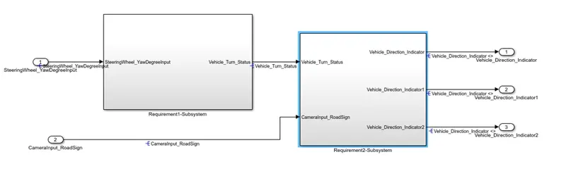
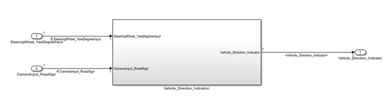
In the Advance Driver Assistant System, this Vehicle direction indication is one of the most important feature for the driver to understand the direction of road sign and to clarify the its driving direction is going correct or not. In this project as per given the requirement we have to develop the two subsystem system separate for each requirement. the first requirement that take input from the Yaw rate in Degrees which is then compare with the limits of Right turn, left turn and straight turn to produce the vehicle turn status. In the second requirement, this vehicle turn status is compare with the rightturn_roadsign, Leftturn_roadsign and Straightturn_roadsign and at last the final roadsign are compare with the vehicle camera input and this result to produce signal of direction indication to driver.
Simulink Model:
1) Requirement 1
Steps to create first requirement 1 simulink model
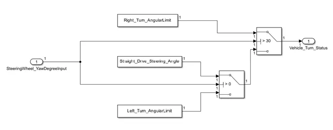
Step 1: Yaw rate signal from the vehicle create the In1.
Step 2: create the three constant block for left_Turn_angular_limit, right_Turn_anguler_limit and straight_turn_anguler_limit.
Step3: Create two switch block to compaire the Yaw Rate signal with above three constant blocks.
Step 4:apply the condition setting to switch block and create Out block forVehicle_Turn_Status.
Simulink Model for Requirement 1:
Description of Requirement 1:
In this requirement we have a input signal in the angular form from the vehicle steering. This value vary between the -180 degree to +180 degree. we created the In1 signal block for SteeringWheel_YawDegreeInput. For the Righttrun_Angular limit, LeftTurn_Angular limit and StraightDrive_Steering_Angle we created three constant block . There are two Switches are use to compare the the SteeringWheell_YawDegreeInput with the above three constant blocks. We apply the condition for switch 1 that if Input angle is greater than 30 then it gives the True value as as right turnangulaer limit. If the Input angle from Yaw rate is between the 0 & 30 then, switch produce Straight drive steering angle and if the Input Yaw rate angle is less than 0 then it give the output LeftTurn_Angular_Limit. This output is then take out by the Out1 named as Vehicle Turn Status.
1) Requirement 2
Steps to create first requirement 2 simulink model
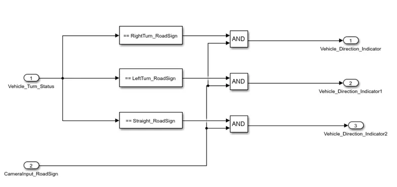
Step 1: Take the Vehicle Turn Status Input of Requirement 2.
Step 2: Create three Relational blocks( Compare to constant) to compare this Vehicle Turn Status to product logical 1 and 0 output.
Step 3: create another In signal block to take the Camera Input as named CameraInput_RoadSign.
Step 4 : create the three relation equal to block to compare the Camera Input with the Compare to constant blocks.
Step 5: finally the result is taken out by Out port as Vehicle Direction Indication.
Simulink Model for Requirement 2:
Description:
In the Requirement 2, we have to take the Vehicle Turn Status from the requireent 1 as input. This input we have compare with the compare to constant blocks which is the RightTurn_RoadSide, LeftTurn_RoadSign and Straight_RoadSign. Create three blocks of relational equal too block to compare with the Camera Input to produce the Vehicle Direction Indication. after the successfully create the model we make the SLDD and linked it with the model and run it.
Main Simulink Model:
Blocks Used:
1)Inport
2)Constant
3)Compare to Constant
4)Switch
5)Equal to
6)Subsystem
7)Outport
Results:
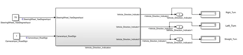
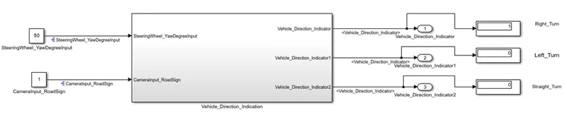
Input 1: when we apply the Yaw Rate greater the 30, then the system produce the output that Right turn Indication
- Yaw Rate_SteeringWheelInput=75
- Yaw Rate_SteeringWheelInput=50
Input 2:
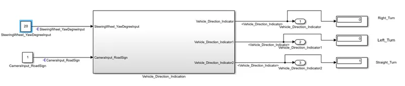
When the Yaw Rate Input is between the 0 to 30 then Vehicle Direction Indicator produce the Straight indication.
- Yaw Rate_SteeringWheelInput=10

- Yaw Rate_SteeringWheelInput=20
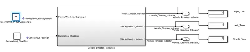
Input 3 :
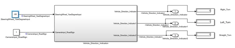
When the Input Yaw Rate signal is less than the 0 then, the Vehicle Indicator Produce Left turn Indication.
- Yaw Rate_SteeringWheelInput= -30
Yaw Rate_SteeringWheelInput= -45
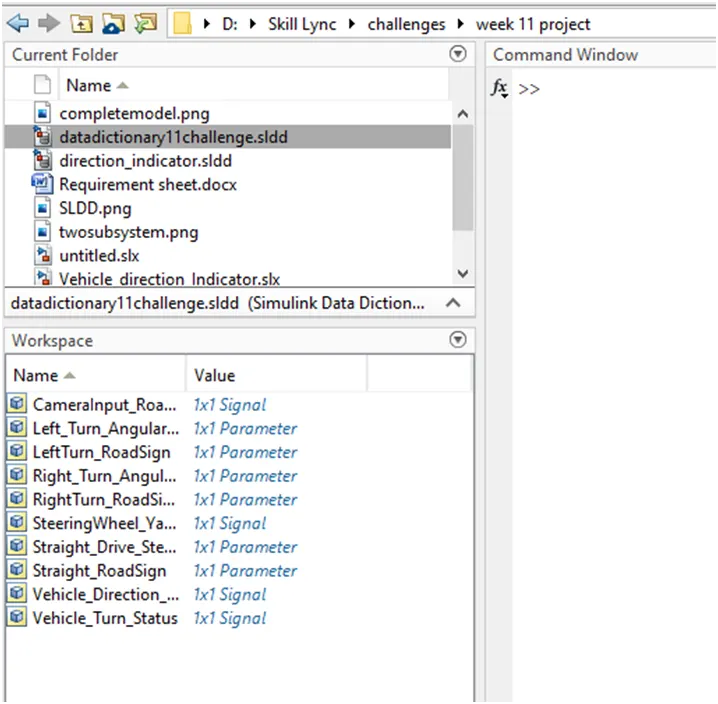
Simulink Data Dictionary:
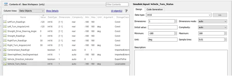
Also we can this SLDD into Base workspace:
Result :
In this way we have Created the Simulink Model for the Vehicle Direction Indicator to Guide the Driver about the Vehicle direction.