Project 1 - Wiper control system and Vehicle speed calculation for ABS using Wheel Speed sensor
Aim: To create the Wiper control system and Vehicle speed calculation for ABS using Wheel Speed sensor and perform the overall V& V workflow.
Objective:
1)Model file Creation
2)SLDD Creation and Linking
3)Requirement Tagging report
4)Fixed point Tool
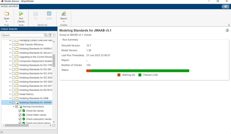
5)Model Advisory- JMAAB
6)SLDV Design and Error detection report
7)SLDV Test generation report
8)Functional Test case, MIL, SIL Harness and coverage report
9)Auto code generation report c & h codes
10)Polyspace report
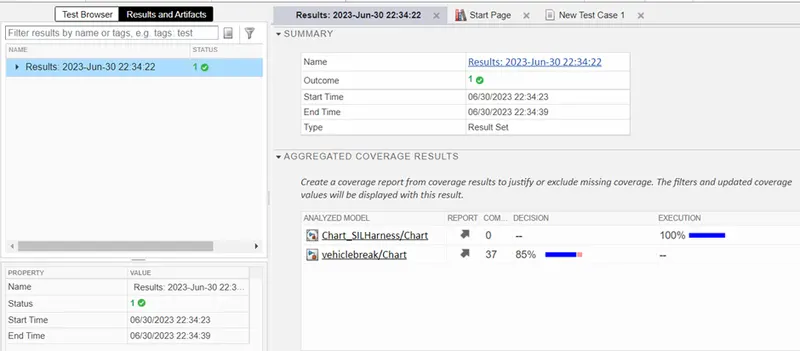
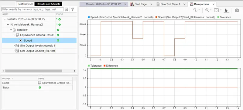
11)Test manager report Baseline and Back to Back Testing.
- Wiper Control System:
Our first objective is to generate the TFT Simulink model. So, here we go step by step procedure for create it.
Description:
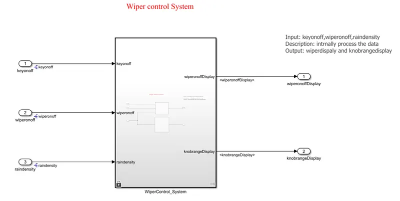
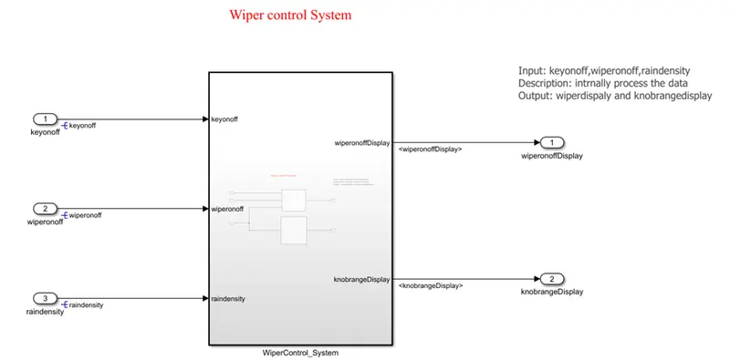
The Wiper control system model we have to develop in this project. There are three conditions are given here which we have to implement during creating the model. In this Simulink model, we have use the one circuit to indication on wiper ON/OFF state and another circuit is to show the output speed as per the condition given here. The speed of the rotating wiper is depend upon the density of rain and on the basis of the density i.e. low, medium and high the wiper rotation and output signal in rpm is also set here.
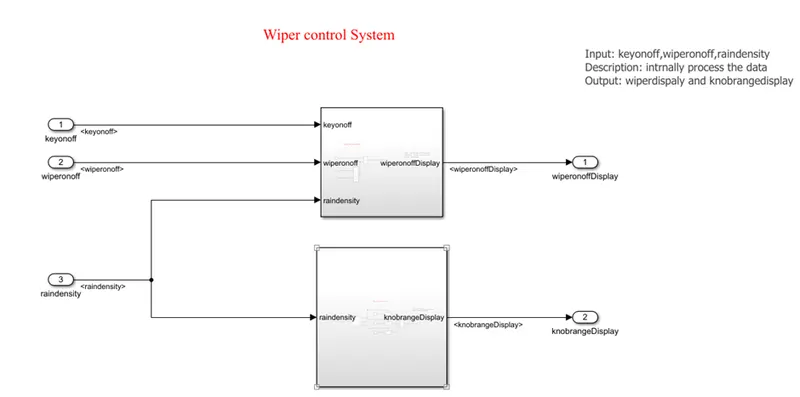
For the development of model, first we use the switch to manually ON and OFF the wiper and this switch connect with the constant block as key ONOFF and further to AND gate. One another wiper ONOFF constant block is connect with the OR gate. nob is connected with the constant block represents the rain density. The output of this rain density is connects with OR gate second input and the output of OR gate is as a input to the AND gate which further connected with the display block to indicate the Lamp ON and OFF. the ON state of lamp shows wiper is on and off state as wiper is off.
The second part of the model is developed for condition given for output of the model. Here, the one connection of Rain density is given to the to the If block. We have to give the condition here as per our objectives. In if block, if input u1 is less than 2 then the first condition will true. We used here if action block to execute the condition. On the basis of the first condition, if action block will gives value as 200rpm at the output display. The second condition is if the input u1 is greater than 2 and less than 4, then second condition will true and the second If action block will give the output as 200rpm on the display. The third condition is If the u1 is greater than 4, then the third condition will true and the third If condition block will gives output as 500rpm on display.
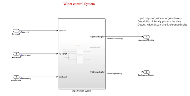
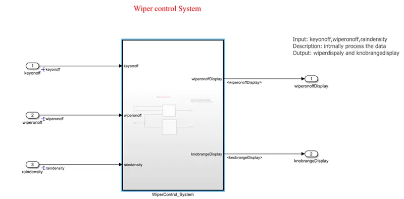
Figure: Wiper model
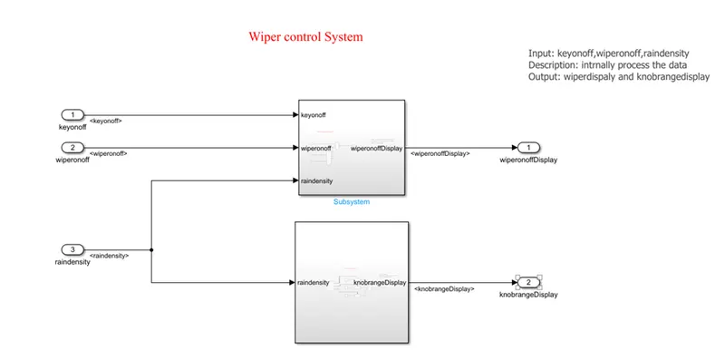
Figure: Sub model of Wiper Control
2.SLDD creation and Linking:
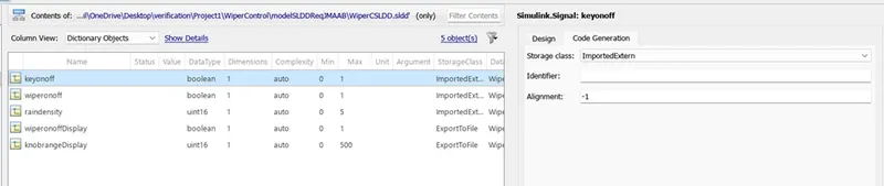
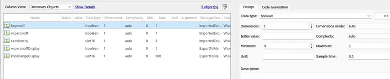
The Simulink data Dictionary is the permanent storage of signals information and parameters. Int this SLDD of TFT project we have created the signals with their data types min-max range, dimension, sample time and storage class etc.
3.Model Advisory Check:
4.Requirement Tagging by Requirement Editor:
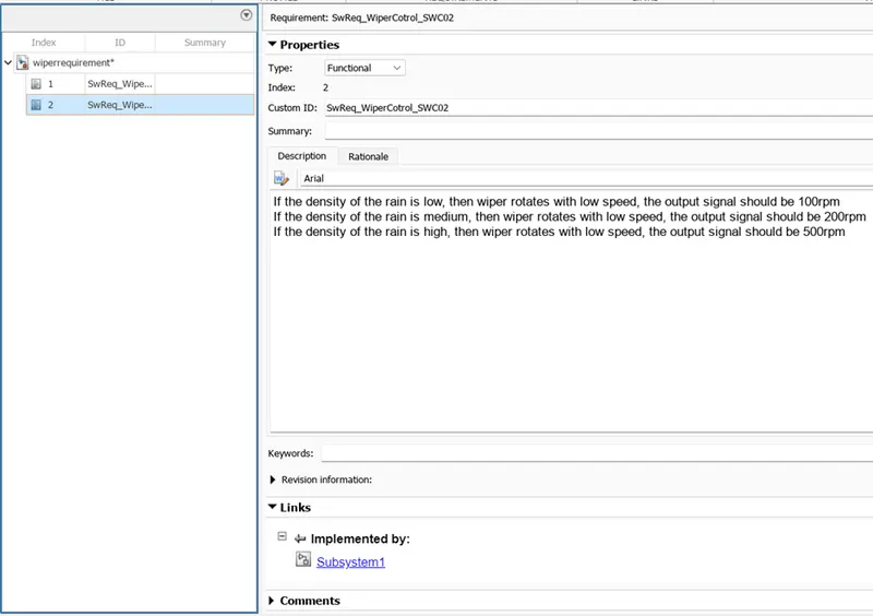
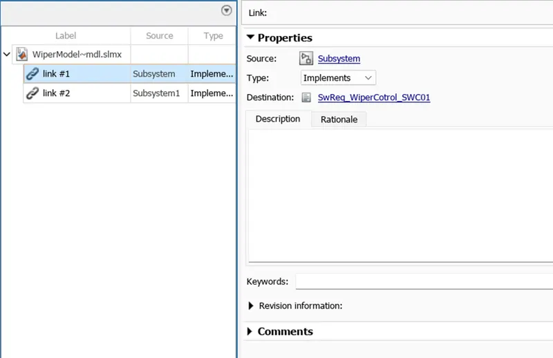
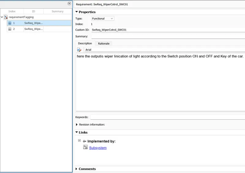
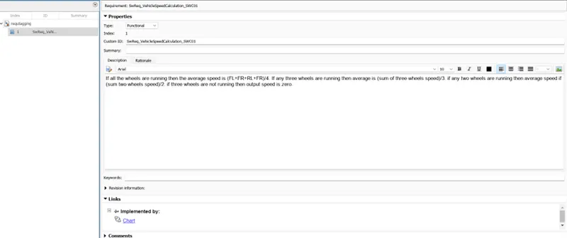
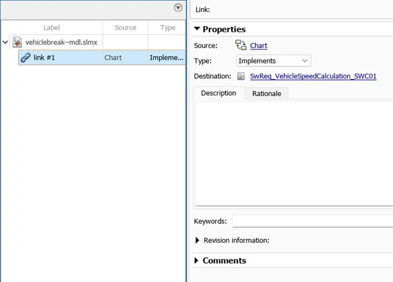
For Requirement Tapping, open the Requirement Editor tool from App . crate new requirement and assign the name to it and save it. By right click on the name shown of requirement file in the console window, insert the add requirement as per need. Select the one by one requirement and copy past the requirement ID and Description of the requirement from the requirement sheet. Select the subsystem from the Simulink model and then select the requirement. Right click on requirement and select the link requirement option. Same procedure follow for all requirement and at last click on save all. For requirement traceability select the requirement manager tool from the App.
5.Fixed Point Tool:
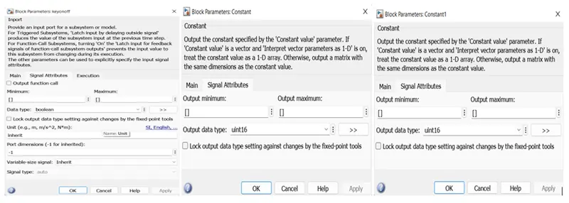
Data type before fixed point tool:
SLDD before Fixed point:

Preparation:

Propose datatypes:
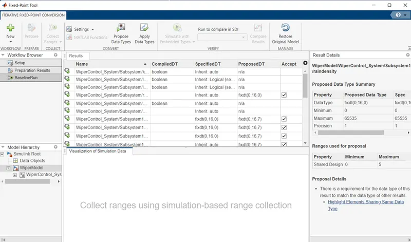
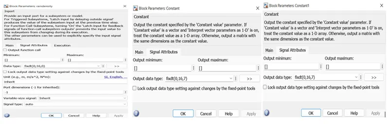
Fixed Point Datatype converted:
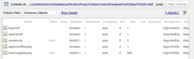
SLDD after fixed point conversion:
6.SLDV Design and Error detection :
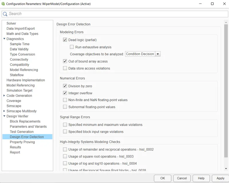
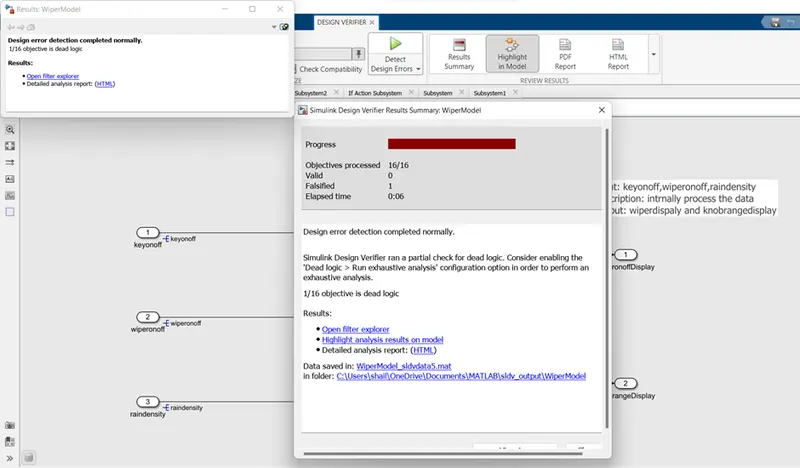
The SLDV check are use for the Error detection and test case generation for the MIL testing. We make setting of solver as fixed step discrete type. First we open the Design verifier tool from the app. Select the error detection mode, set the time and name of model. In setting click on dead logic , output boundary, division by zero, and integer overflow and click on ok. Check the compatibility. Run the model for detect the design error. Go to check the HTML analysis report.
A] Error detection mode:
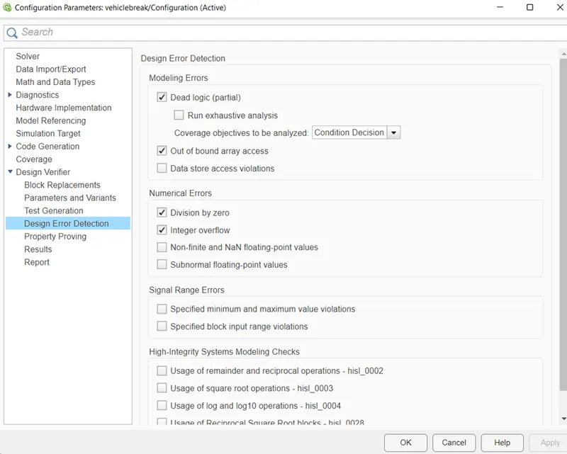
Go to app, select Design verifier and select the Error detection mode. Click on setting and select the dead logic, out of boundary array access, division by zero, and integer overflow.
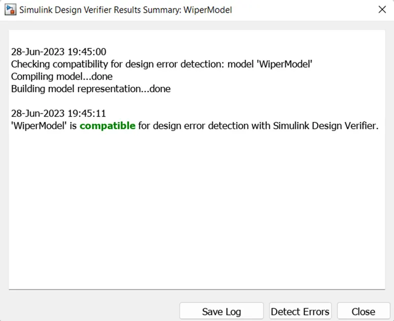
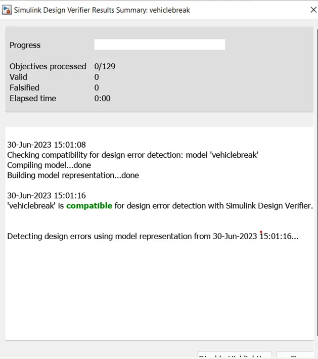
Check the compatibility of design model:
Detect the design error and generate the HTML report:
B] Test generation mode:
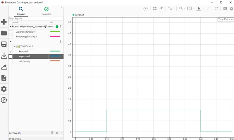
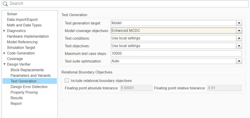
Change the mode of SLDV into Test generation and check the advisory report. Click on setting and set the coverage as MCDC, select the step size as 1000 ,and test suit as Auto. Next click on generate the test and check all the documents generated. like MIL test harness, test report, coverage report etc.
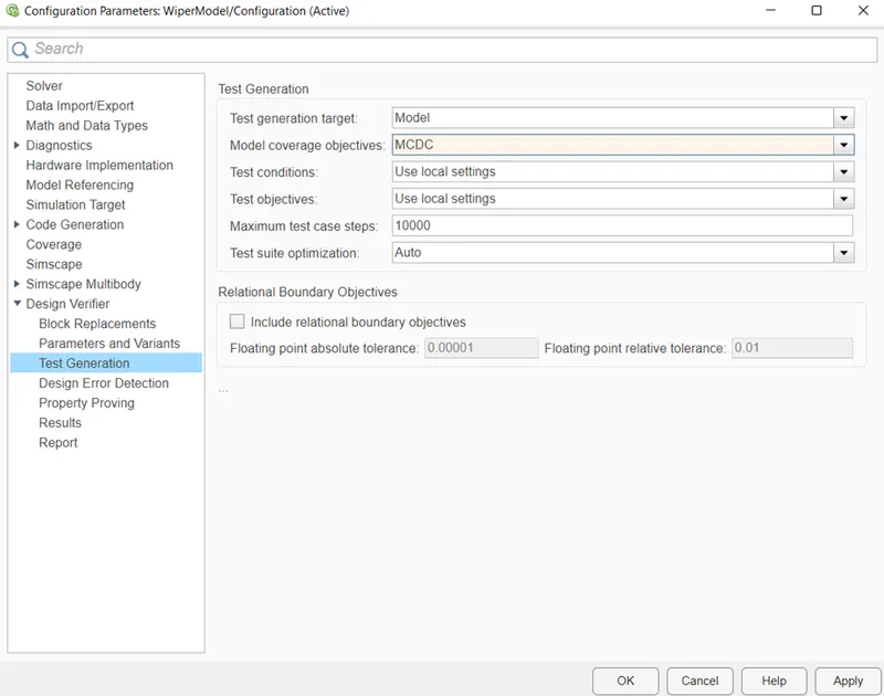
Figure: Test generation setting
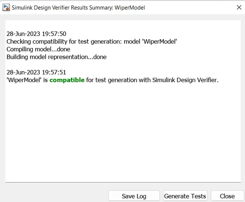
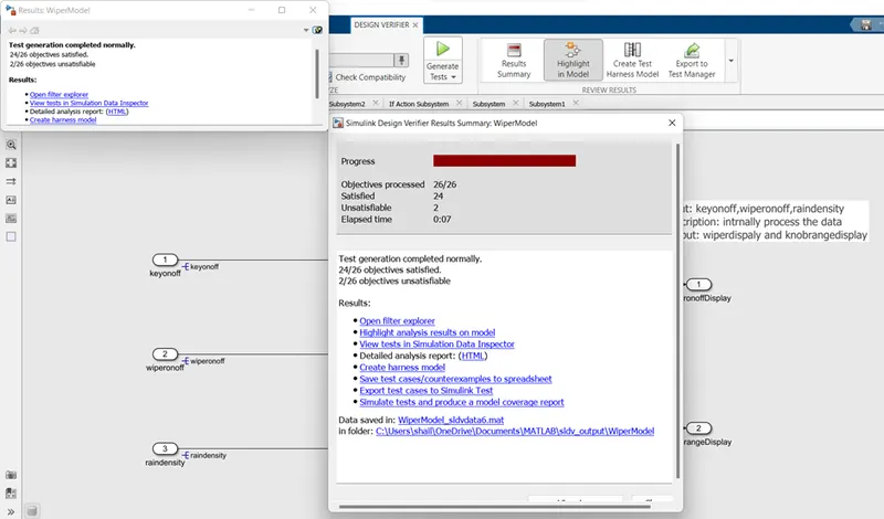
Figure: Test generation
Results:
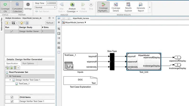
Figure: MIL test Harness
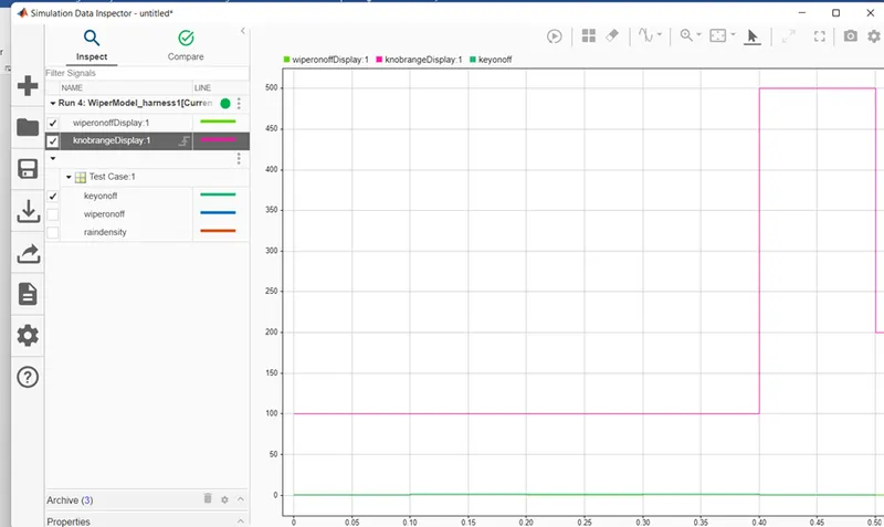
- Steps for MIL Testing:
1) open the model and make the Solver setting and configuration setting.
2) Convert the Model into Atomic subsystem.
3) Run the to insure that there is no error present in the model.
4) Generate test Harness.
5) upload test cases into signal editor for input signals.
6) connect the outputs of signal editor to output viva add block.
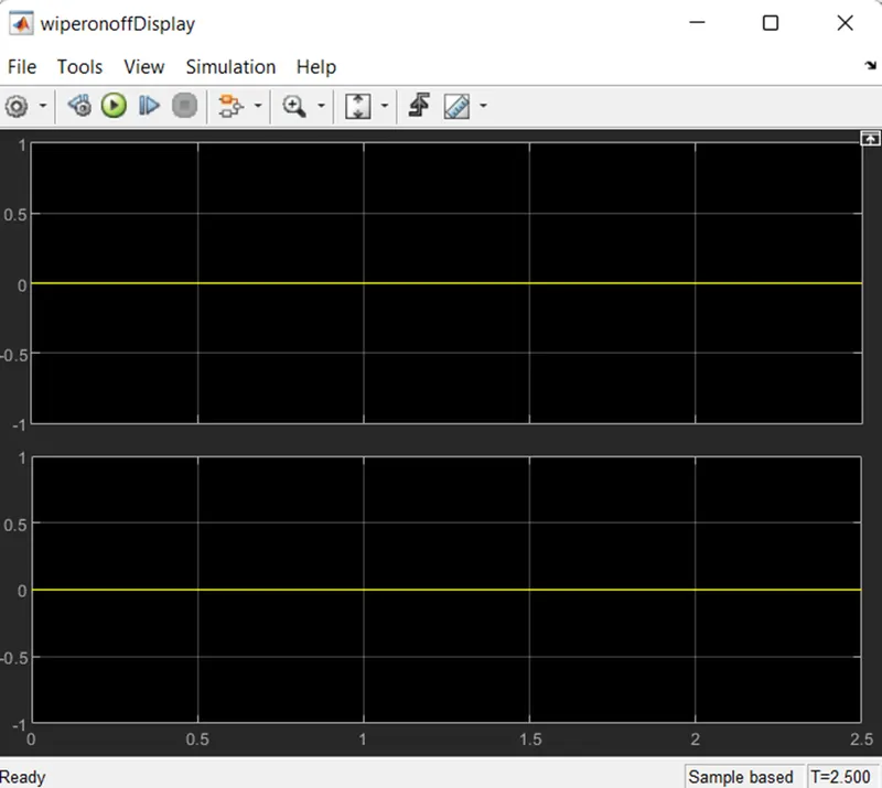
7) run the model and check the output of scope showing as zero signal.
Description:
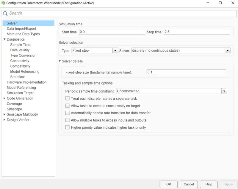
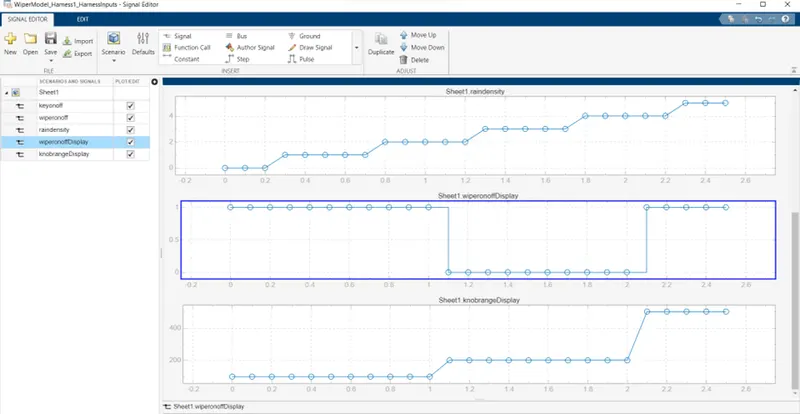
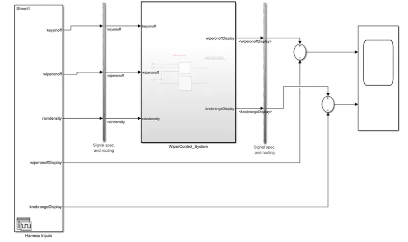
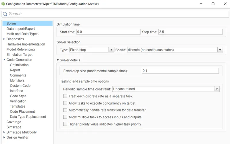
firstly open the model parameter setting in that we have to make solver setting. so click on solver setting and assign start time as 0, stop time is 2.5 sec and sample time is 0.1 sec. to convert the model into atomic subsystem, right click on the subsystem and select the block parameters one window will open, from this window click on check box of the treat as atomic subsystem. the subsystem block will get highlighted. next is generate the test harness. to generate the test harness, right click on the atomic subsystem and select the test Harness option, in that will appear in that window select create test harness option. now we have select the Source as Signal editor and sink as Scope. this will create our model into new window and with signal builder in input and scope block at output. now its time to export the test case signals into the signal editor. connects the outputs port of signal editor to outport of atomic subsystem viva add block and subtract this signal from the output of the model. if the output of the scope is perfect zero then the MIL testing is 100% successfully conducted. otherwise if any varying signal is seen in the scope then make correction and run it repeated.
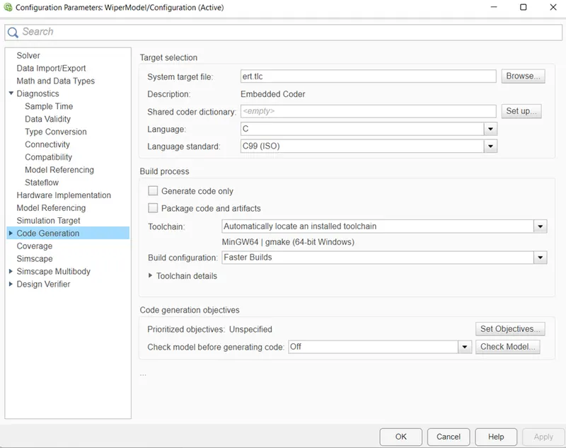
Solver setting and code generation setting:
Atomic model:
Test Cases:
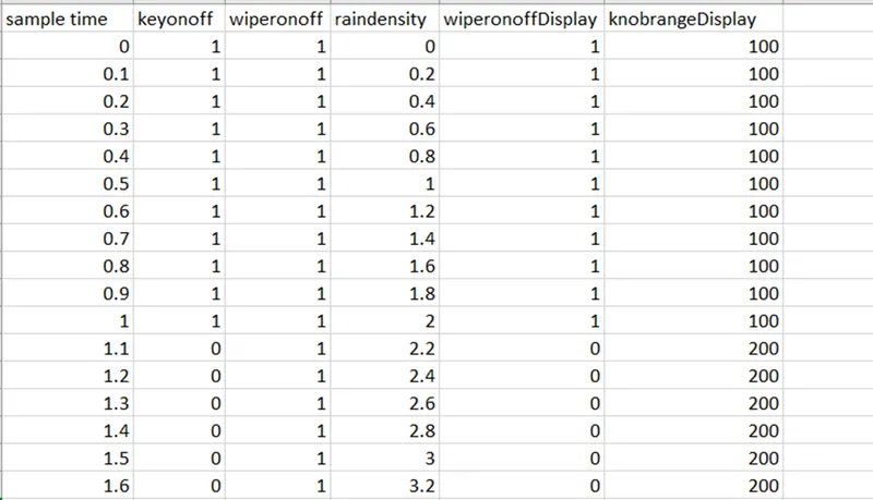
Test case upload into signal editor:
MIL Test Harness:
Result:
- SIL Testing:
Steps for MIL Testing:
1) open the model and make the Solver setting and configuration setting.
2) Convert the Model into Atomic subsystem.
3) Run the to insure that there is no error present in the model.
4) Generate the code using Build.
5) Generate SIL test Harness.
5) upload test cases into signal editor for input signals.
6) connect the outputs of signal editor to output viva add block.
7) run the model and check the output of scope showing as zero signal and take coverage report.
Description:
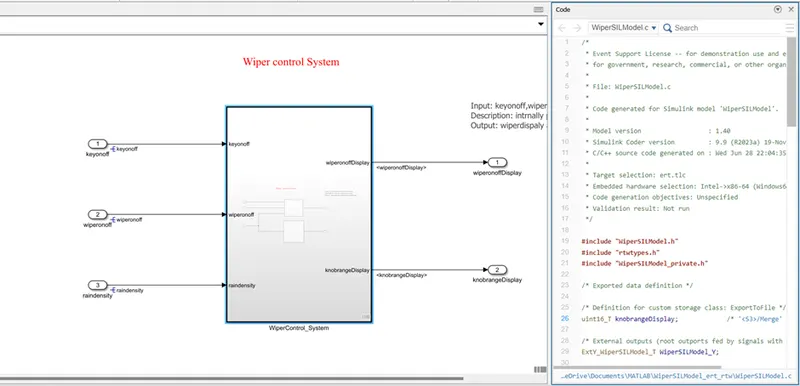
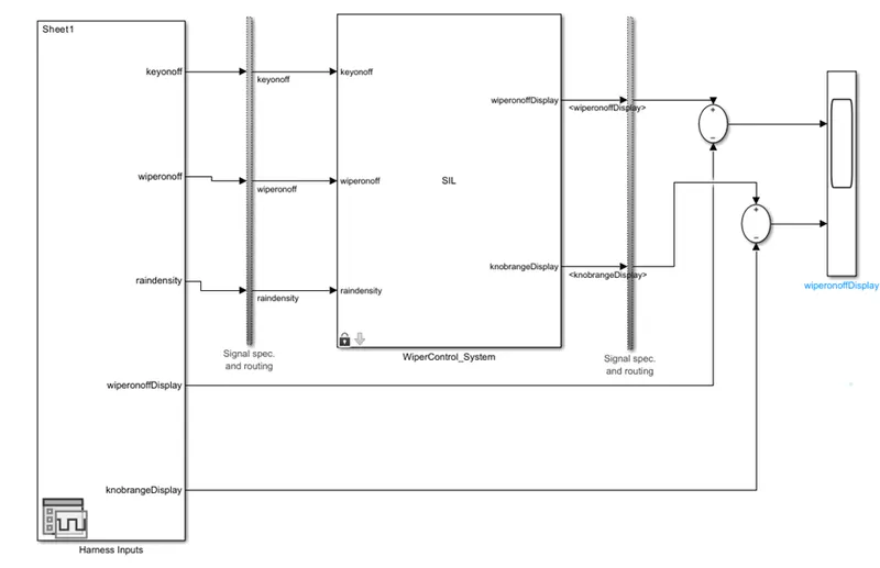
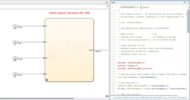
The SIL testing is always perform the MIL testing is successfully done and code generation. For that we have to follow the above steps First opened the model and its respective init file in MATLAB. Now we do the model configuration setting for the simulink model. So for that go to model configuration setting click on model setting. After that go to solver and select the starting time 0, stop time 1 and sample time 0.1 of the solver setting. next step is to setting of code generation, from that select the Embedded coder language and remaining parameters get automatically selected. For the coverage setting , click on enable coverage analysis. Also select the coverage as MCDC and other metrics and apply it. Next step is to convert the model into atomic subsystem so for that right click on model and select the block parameter option and new window will appear on the screen , from this we have to select the check box of create atomic subsystem. ones run the model to insure the error is not present in out simulink model. Next step is to generate the code. Click on Build option from the simulink task bar and from that select the select the embedded coder app form that, select the generate code option and wait for some time, it will create the code for our simulink atomic model. At the last we have to convert this atomic model into SIL model. To generate the SIL model , we have two ways. One it right click on the given model and select the Test harness option, from this new window will appear beside it and select create for option. After also new window will open from that window we have to select the source as signal editor and sink as a scope. From the same window select the advance setting and select the Software in loop which will covert our model into SIL model. The second method to generate the SIL is right click on model and select C/C++ and click on generate S-Function. from new window click the check box of generate SIL. Id we want to add any parameters then we can add otherwise click on ok and build.
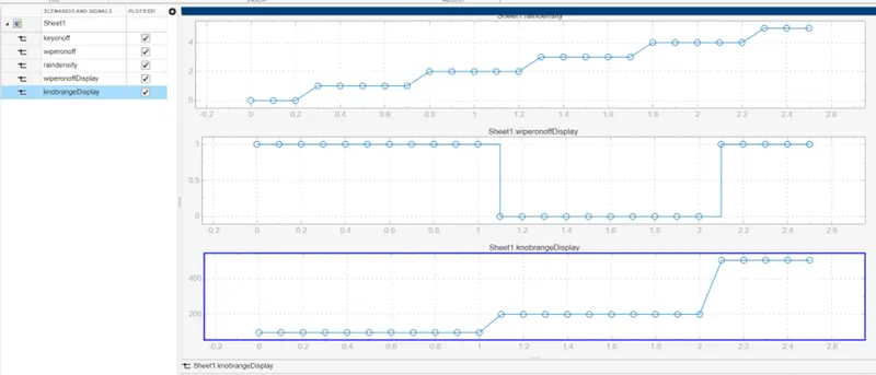
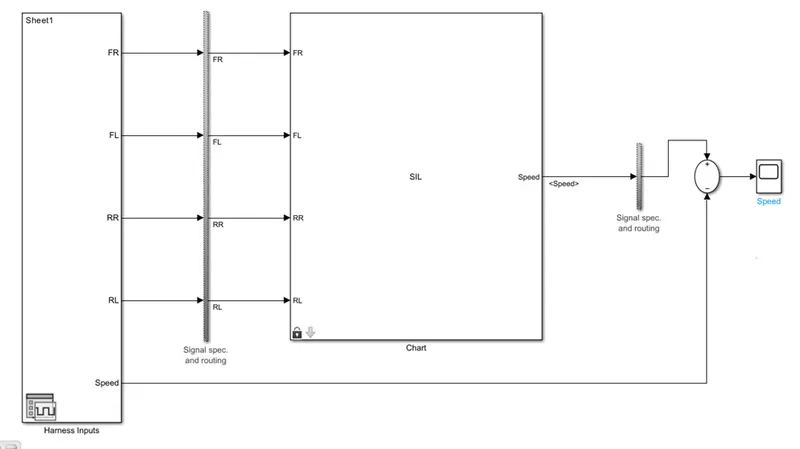
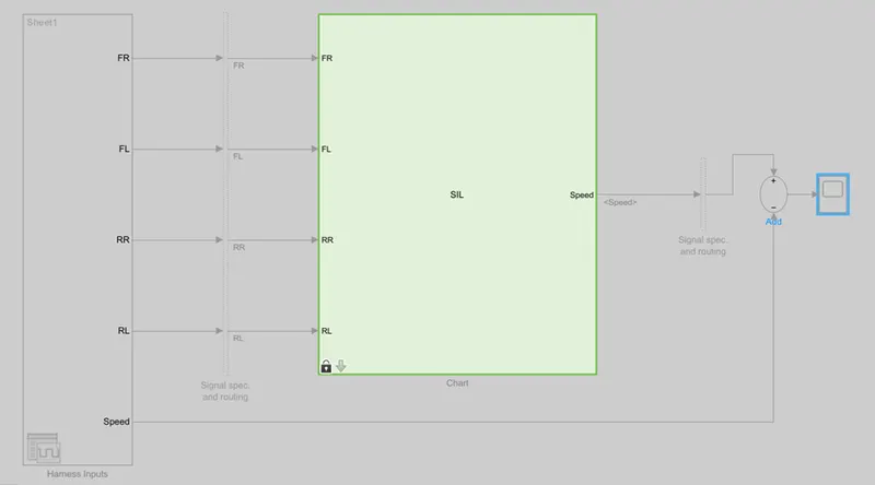
Al last, the new SIL model will generate into new simulink window with signal editor at input side and scope at last of the model. Generate the test cases into excel sheet and upload it the signal editor. After that as per our input and output requirements, numbers of port will appear on signal editor. Connect the outputs of the of the signal editor to output of SIL with the help of add block with subtracting from output and observe the scope output are zero showing. Also we get the coverage report to see the status about the SIL testing.
Simulink Model:
Generate the Embedded code:
Test case upload in signal editor:
SIL Testing Harness:
Result:
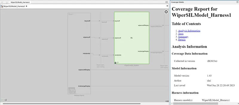
SIL Coverage:
9.Poly Space report:
Steps for Poly space Bug finder Analysis:
As we stated above it generate the bug report, code violation report and cod equality matrix reports.
Step1: Open the project, go to app and select the Polyspace static code analyser.
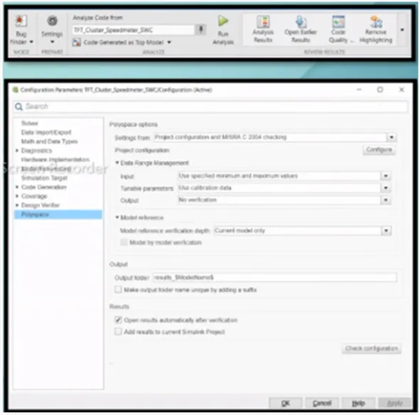
Step2: select the setting option and click on polyspace option for he window.
Step3: form the setting select setting from Project Configuration& MISRA C2004 setting. Input option use for minimum and maximum values. Tuneable parameter can be use calibration data. Set the output as No verification. Enable the check open verification result after verification.
Step4: in bug finder code configuration select the source code language as C or C++ as per the requirement.
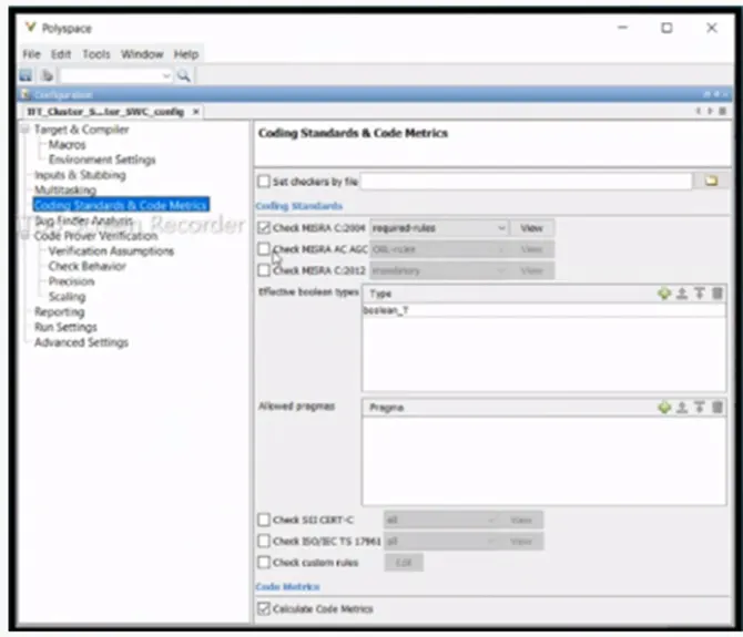
Step5: next click to code standard and code matrix, form here select MISRA C or CERT C guideline as per industry standard use.
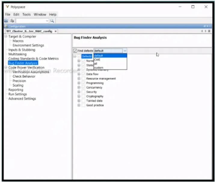
Step6: select bug finder analysis, based on run time error or code errors. We can also select it as default.
Step7: At last click on Run button, it will give the Analysis report. Also go to source code to find the error and we can check and correct it.
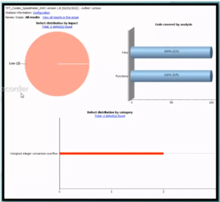
Steps to solve Polyspace code prover:
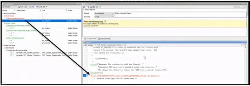
This code prover are use for overflow, divide by zero, out of boundary array access and other runtime errors detection. Here color coding is use to indicate the various errors.
Step1: Change the mode of Polyspace tool form Bug finder to Code proven.
Step2: select the code prover verification form the window and click the radio button to Enable it.
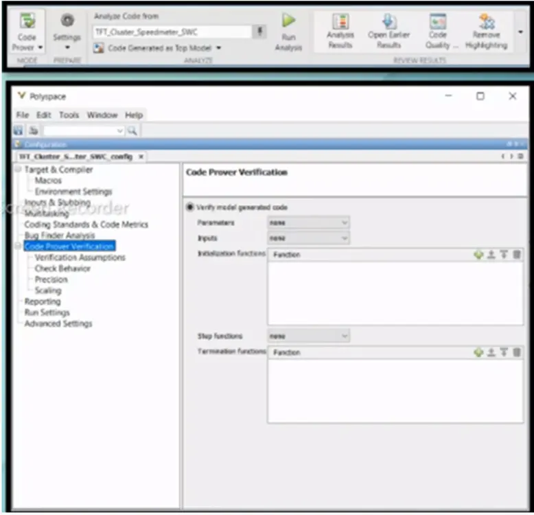
Step3: Run the analysis.
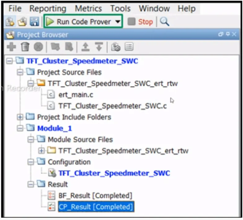
Step4: check the Analysis report, here green colour shows completely pass, red colour shows the error, also see the coverage report.
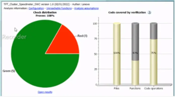
Step5: if any warning in red colour then click on that, it will open the code. Make correction and run repeatedly.
Result:
In this way we have use the Polyspace Code Analysis for the given model to find the Bug into the generated code and code prover also.
- Simulink Test Manager:
Requirement linking for Simulink model
Step 1: make the solver setting as Fixed step and Discrete type, the starting time is zero and stop time as per model test cases.
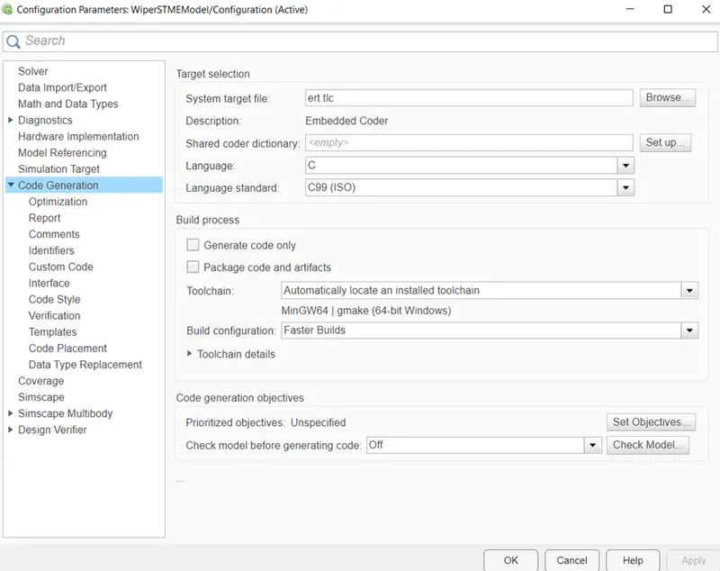
Step 2: make the code generation setting as ert.tlc Embedded coder.
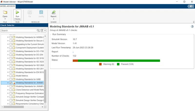
Step 3: take the model advisory report according to standard guideline JMAAB.
Step 4: Go to App and select Requirement Editor Tool, select new requirement set and save the with name in slreqx format.
Step 5: at left console generated file, right click and select add requirement as per model needs.
Step 6: select req. 1 form console, copy the requirement ID and past into editor window also copy the description and past into editor window. Apply same procedure for all requirements.
Step 7: come on Simulink model select the subsystem, go to requirement in req. editor tool select it and right click on it and select the link requirement option. Apply same for all subsystem.
Step 8: complete the above process and select save all from task bar. It will save the file in slmx format.
Step 9: click on show link option in task bar and observe the all generated link of requirement. We can change anything in model and can see the changes in editor tool.
Step 10: Click on export to generate report, give the name to file, time and select generate report and save it in folder.
Base line testing Steps:
Step 1: make solver setting-start time 0, stop time 2.5, fixed step discrete, sample time 0.1, coder setting ert.tlc Embedded coder and coverage ON
Step 2: Create the Simulink model as Atomic model.
Step 3: check any Testing Harness is not generated for model and run the model.
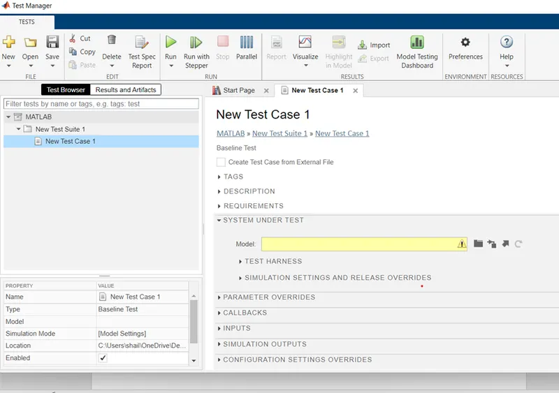
Step 4: Open the Simulink test manager app, new window will appear, select new test file and save the file it will create the folder test related data.
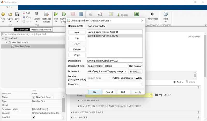
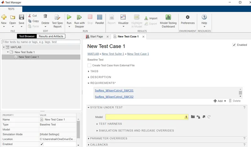
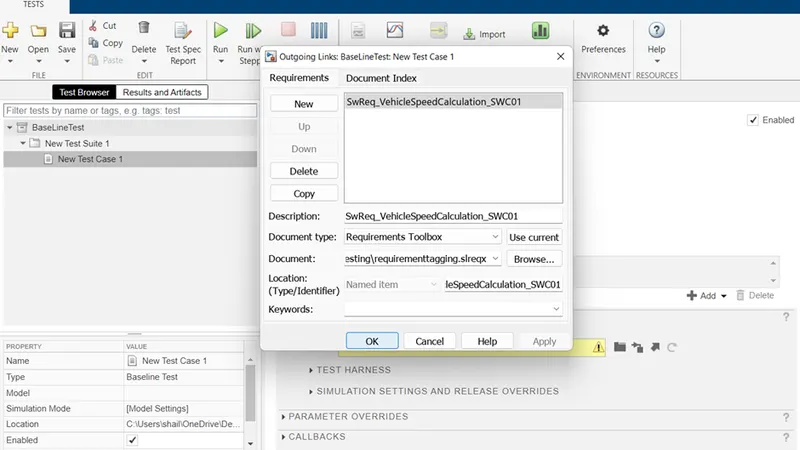
Step 5: click on requirement (we have already linked with req. editor), click on add, select new, click on document type as Requirement set. Click on brows open the requirement matlab file(slreqx) generated by requirement editor tool. Click on document index we will see here all requirements present here. Select one requirement and click on apply. Same procedure use for all requirements.
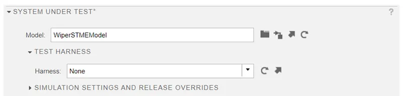
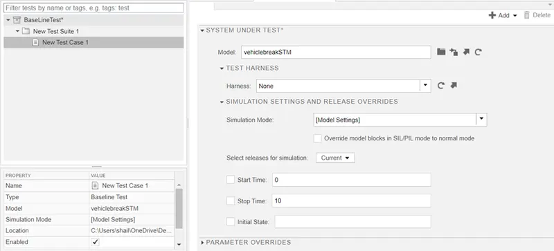
Step 6: select the option system under test and click on current model symbol. Also select test harness option and click on none.
Step 7: select the simulation output setting(we have already done in step 1)
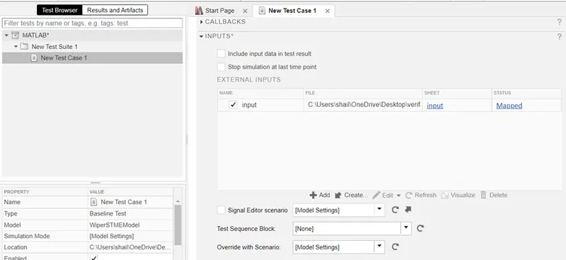
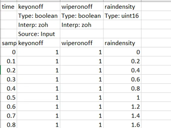
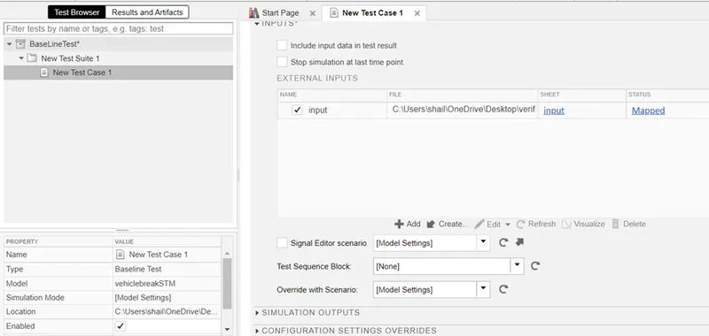
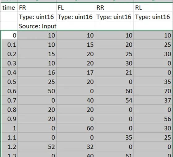
Step 8: select the Input( to create automatic test cases), do to create(external input)-small window will appear. Select excel sheet option, Click on file icon and select create. It will create excel sheet(testcase baseline) of test inputs. Copy all time, and inputs data of old test case excel sheet into the newly created excel sheet and save it.
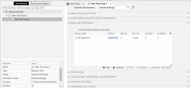
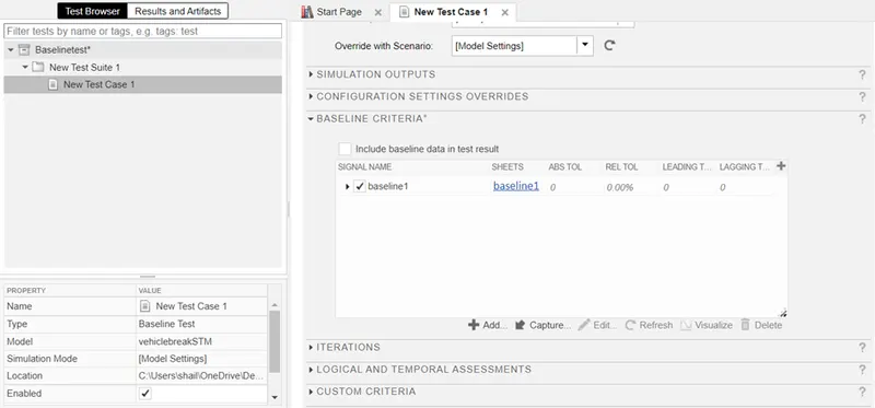
Step 9: select the Baseline criteria. Click on capture. Brows the above created testcase baseline sheet, it will ask for replace, click on yes. Give the sheet name and click on yes on message of overwrite existing. After this procedure done, go to excel sheet we will see outputs are calculated in the sheet.
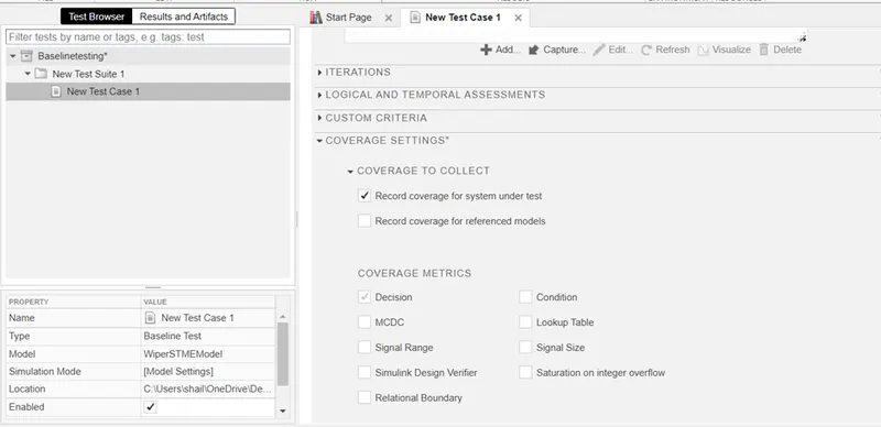
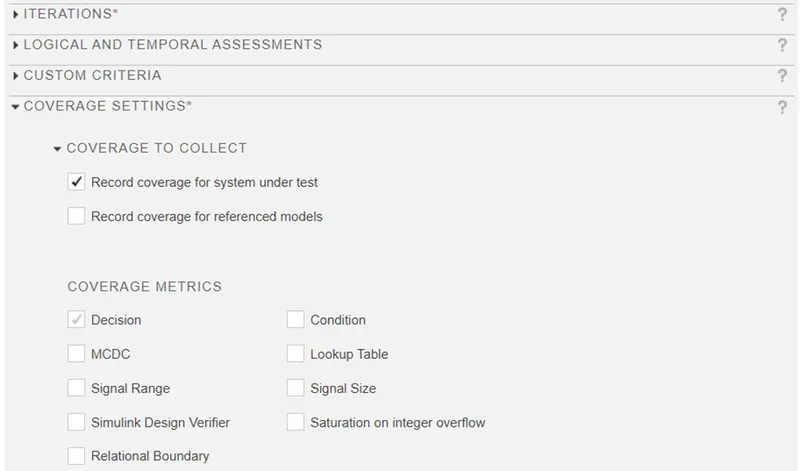
Step 10: Select the coverage setting, click on record coverage for system under test ( it will compare the result actual and expected). We have use MCDC coverage.
Step 11: save and run the test manager.
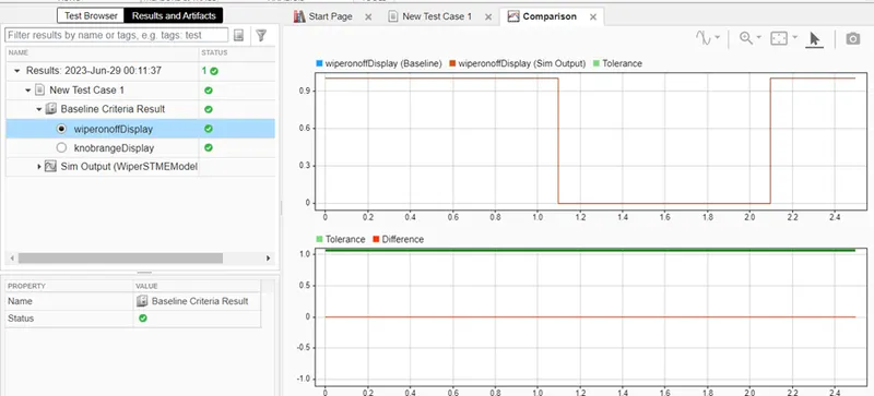
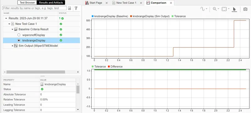
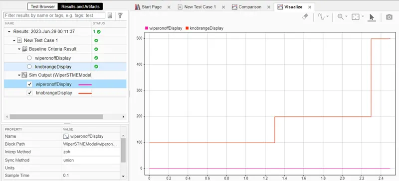
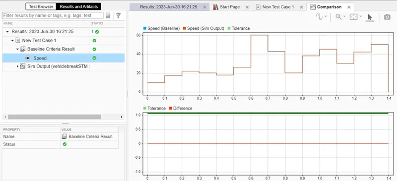
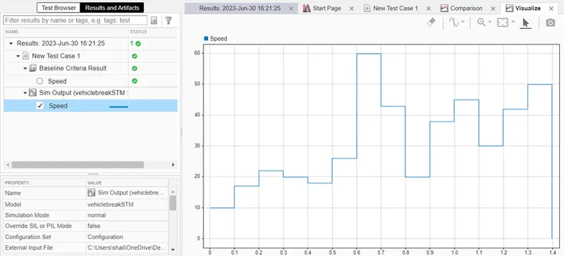
Step 12: under the test and results, we can see the Baseline criteria output, Sim output. Green colour line sows the successful result.
Step13:go to result and right click on it, select export result and save the file.
MATLAB Simulink model
MATLAB Simulink subsystem:
Solver and Code generation setting:
SLDD Creation:
Model Advisory check:
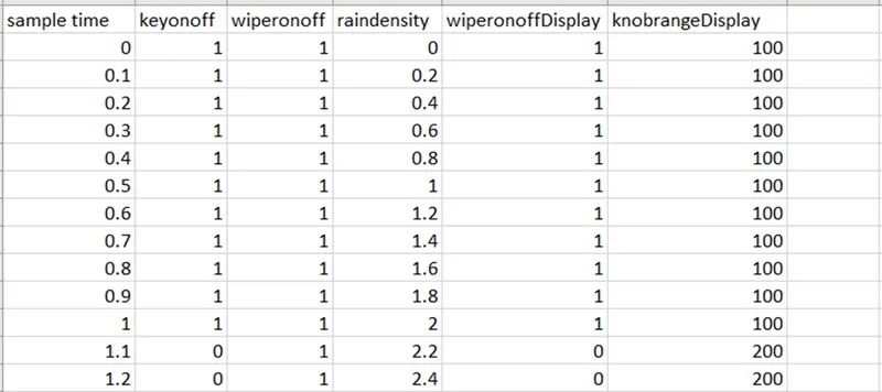
Test Cases:
Requirement linking by Requirement editor:
Requirement upload:
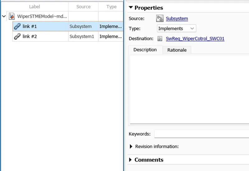
Requirement traceability:
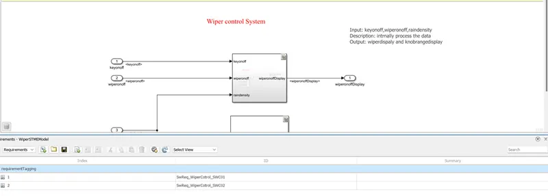
Baseline Testing :
New test generation:
Requirement adding:
System under test:
Input setting for test case template generation:
Base Line Criteria:
Coverage setting:
Run the Model:
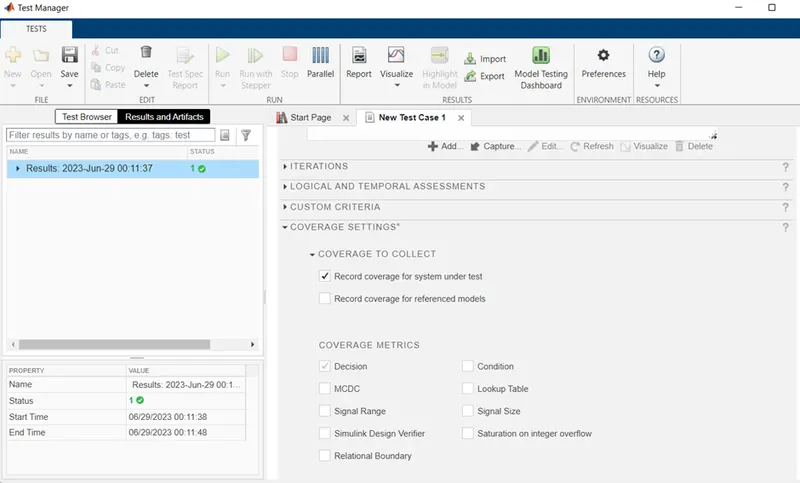
Result and Artifact:
Back to Back Testing:
Step 1: Open the model Make it Atomic, check no test harness created. Select Simulink test manager it will open the test manager window, select new test file, save the file in folder with appropriate name.
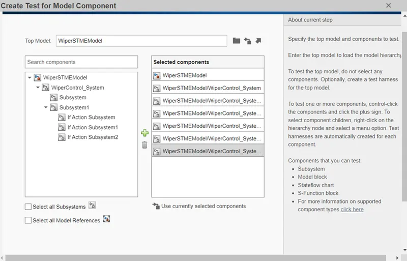
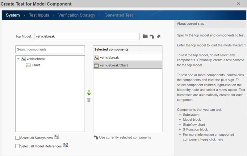
Step 2: select new and select test for model component, new window will appear. Click on the current model component icon and click on next.
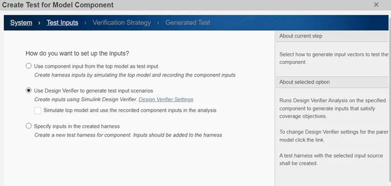
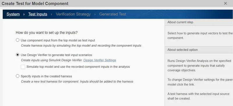
Step 3: next window ask foe how do you want to set up inputs, then click on design verifier and click on next.
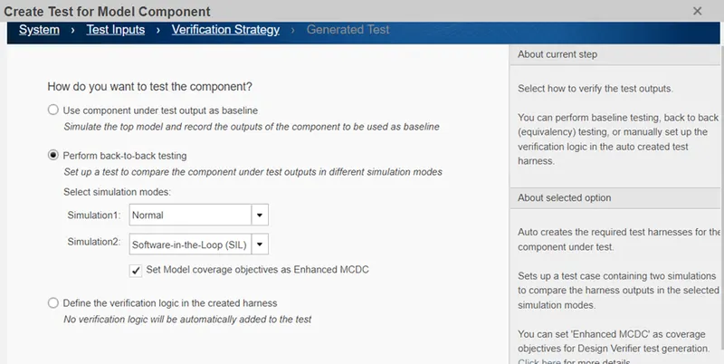
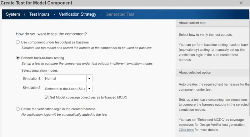
Step 4: next window ask for how you want to test component. In that select Back to Back testing option, Simulation1 as Normal MIL and simulation2 as SIL. click on next.
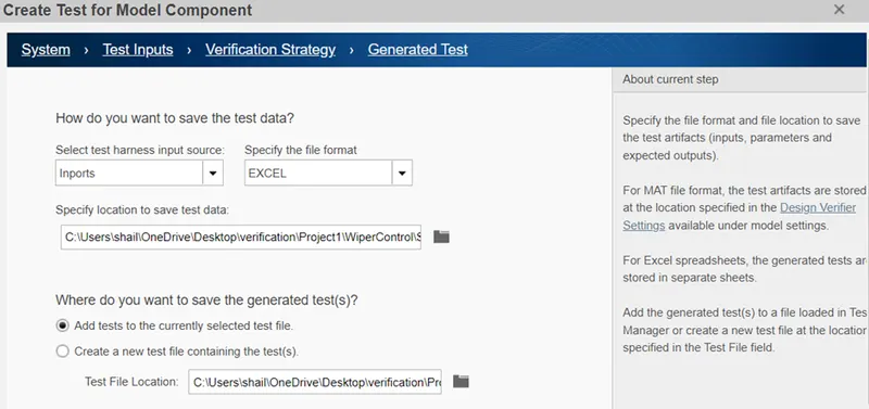
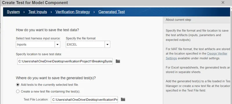
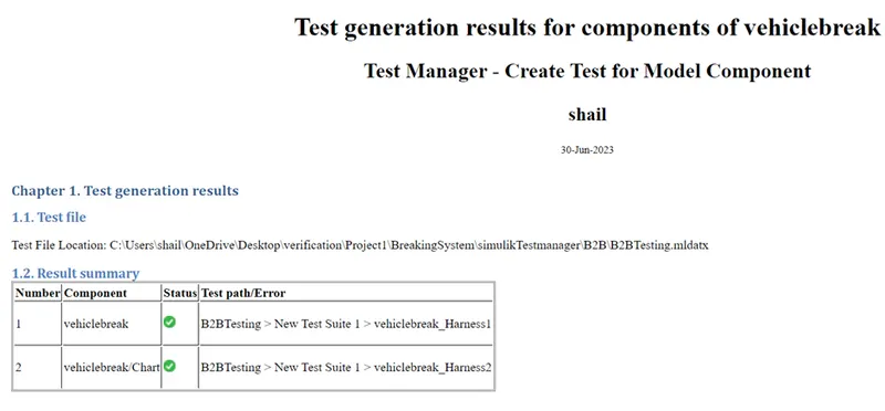
Step 5: next window ask for where to save the excel, select the path and click on done. The test case will generate in this folder. After this process complete harness model will created and also we can see it into test manager tool window. also HTML report get generated.
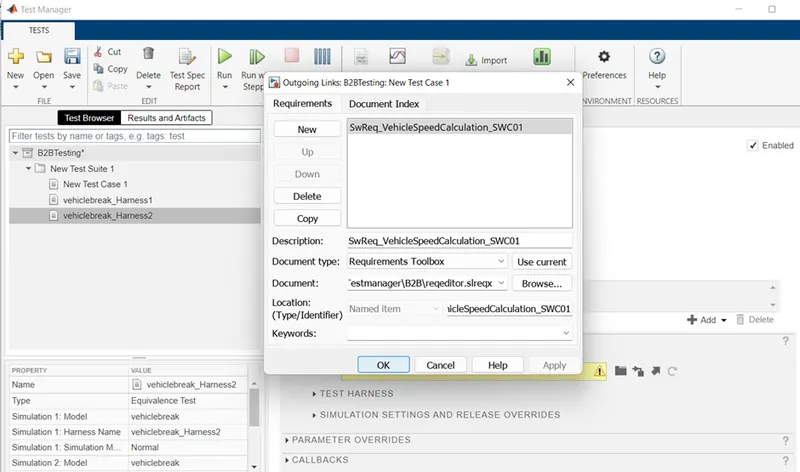
Step 6: after that we see simulation 1 and 2 is present on the under the model harness on test manager window. Add requirement as previous Baseline and click on ok.
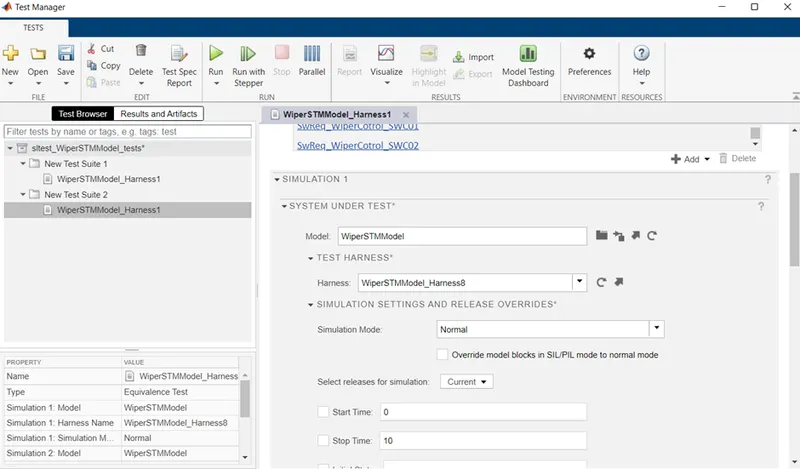
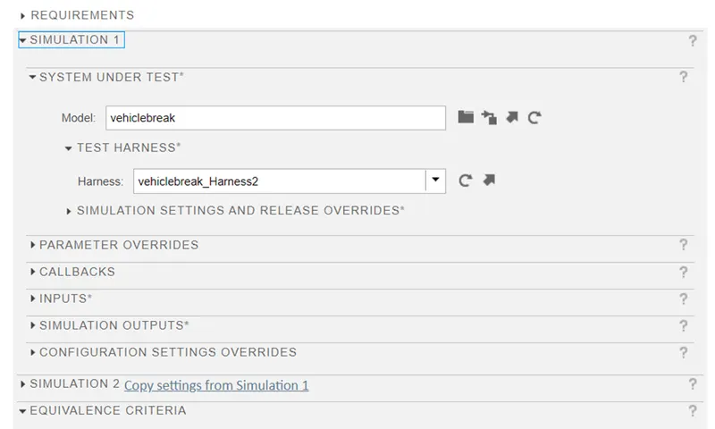
Step 7: under simulation1 see the setting only. In Input select the checkbox of signal editor scenario.
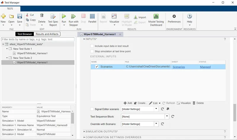
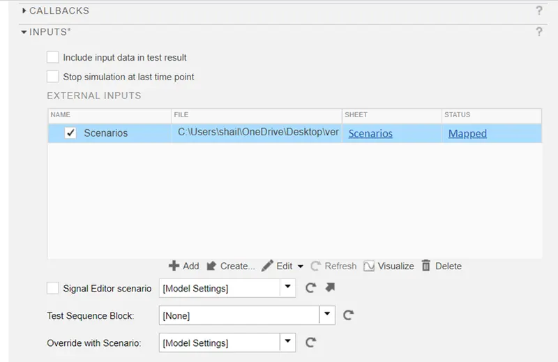
Step 8: under simulation2 go to input and click on scenario box.
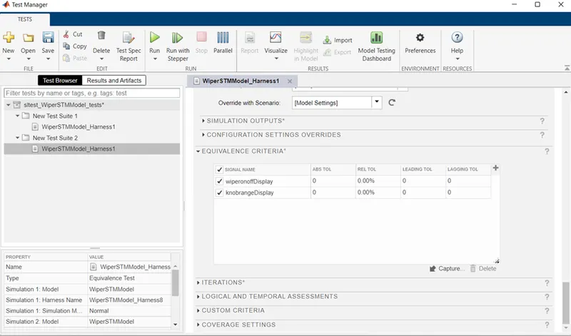
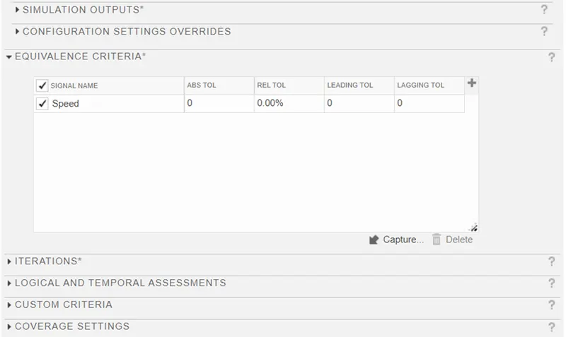
Step 9: select the Equivalence criteria, select the capture it will calculate the output.
Step10: go to our saved folder we can see all the generated.
Add model for B2B testing:
Test case components and inputs and file save:
Requirement Tagging:
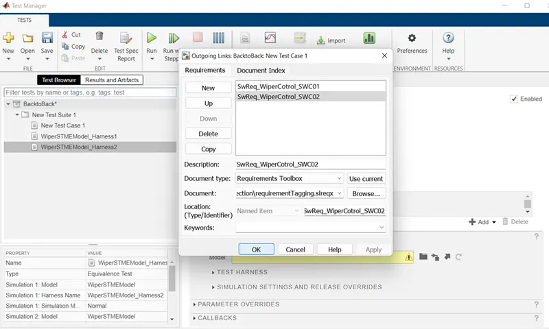
Simulation1:
Simulation2:
Equivalence criteria:
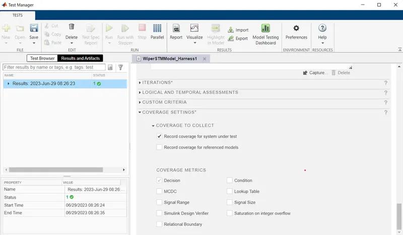
Coverage Setting:
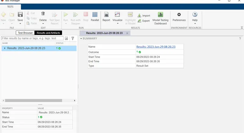
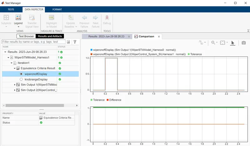
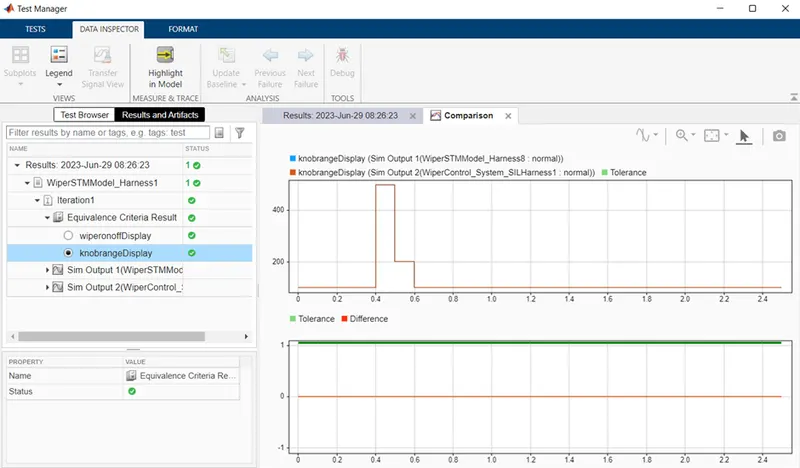
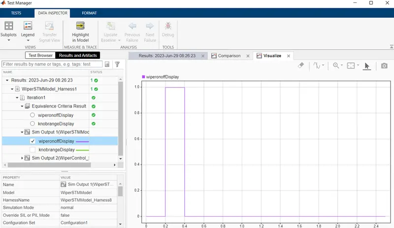
Result and Artifacts:
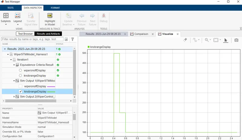
B} Vehicle Speed Control by ABS:
Description:
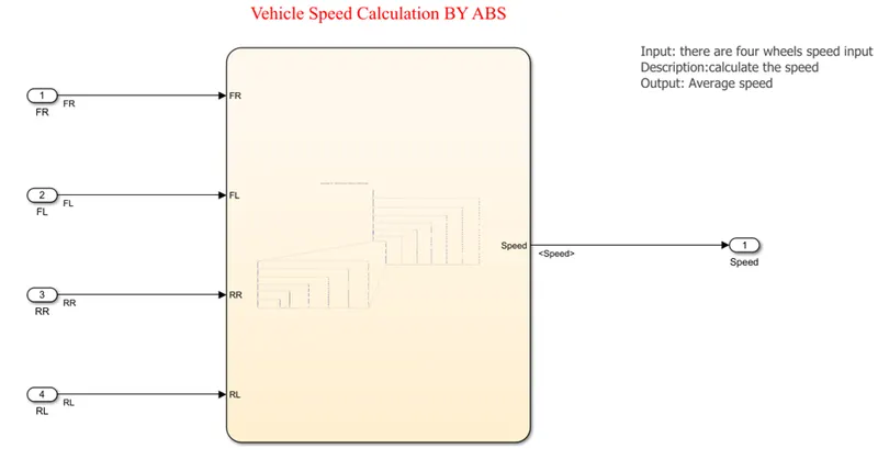
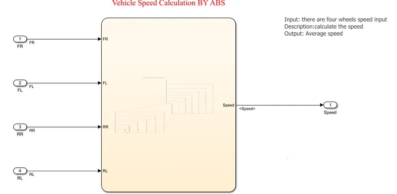
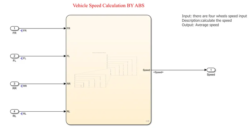
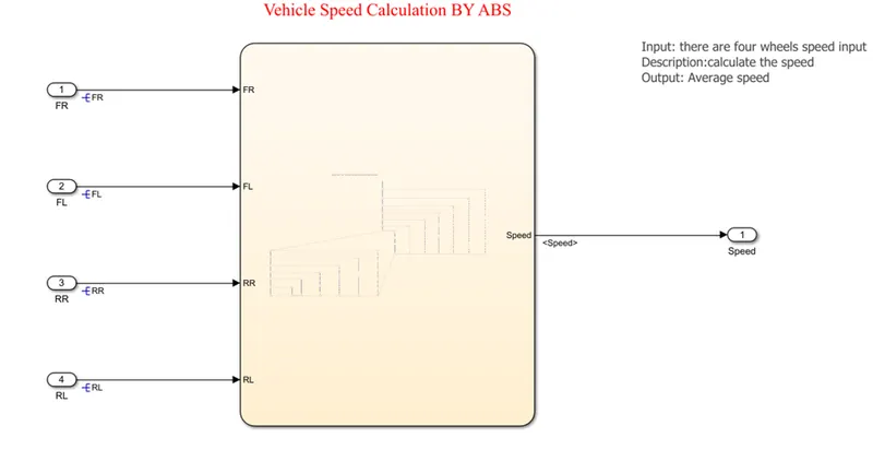
Here, in this simulation we have develop the model for the speed calculation of the vehicle by Antilock breaking system. The vehicle have four wheel and they have separate four sensors which continuously monitor the speed of the wheels and gives the signals to calculate the speed of vehicle. So, here we have to take four constant blocks for four wheels input. Insert four knob to as for speed vary and connect with the constant block. Give the name FL, FR, RL, RR to each block as front right, front left, rare left and rear right respectively. Insert the state chart block to implement the above given objective logic. There are two way to design the logic as state flow and state chart. W ego for state chart. We use the default transition as starting of the chart and use the junctions to connect the conditions and actions. We created here horizontal transition as condition and Actions as vertical manner.
The complete Vehicle speed calculation by ABS Simulink model is shown in following figure.
1.Simulink model of Vehicle Speed Calculation:
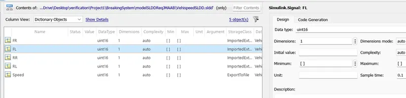
2.Simulink Data Dictionary:
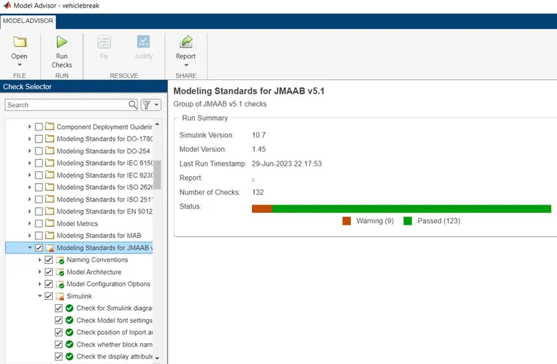
3.Model Advisory by JMAAB:
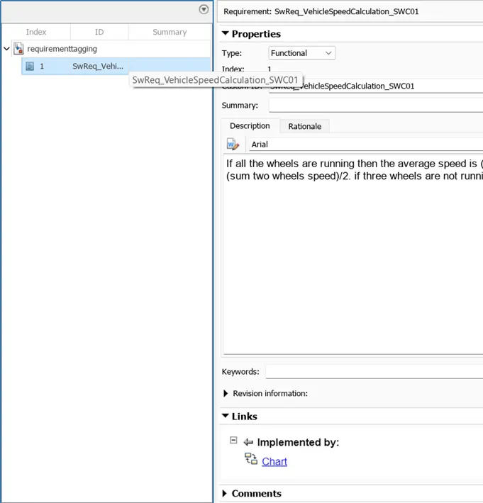
4.Requirement Tagging:
5.Fixed Point Tool:
SLDD before fixed point:

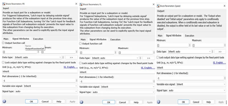
Block Data types before Fixed point:
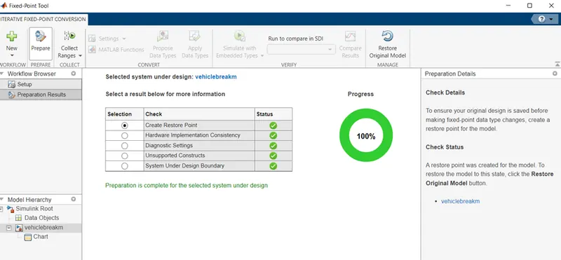
Preparation for Fixed point:
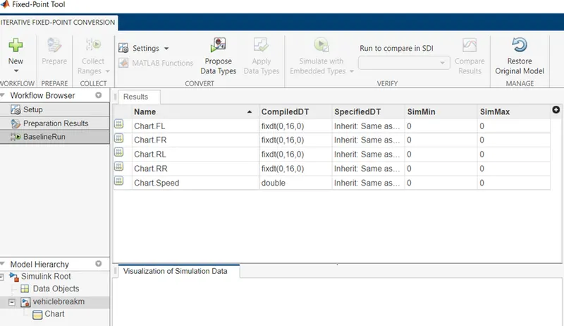
Range collection:
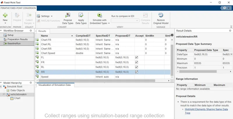
Apply fixed point datatypes:
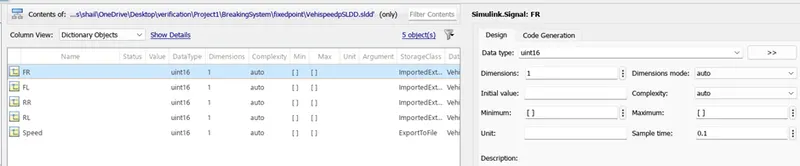
SLDD after fixed point apply:
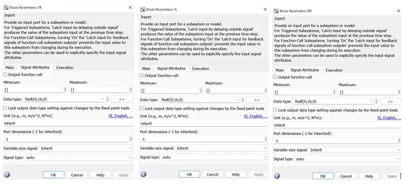
Block data types after Fixed point:
6.Model in Loop Testing:
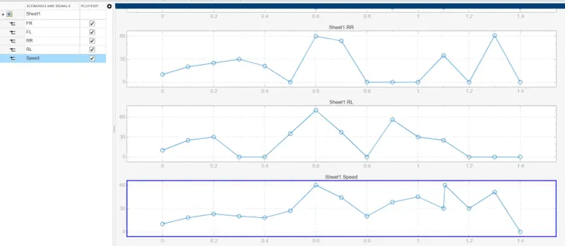
Test cases upload:
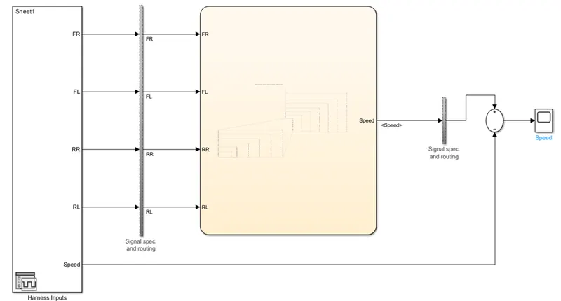
MIL Testing Harness:
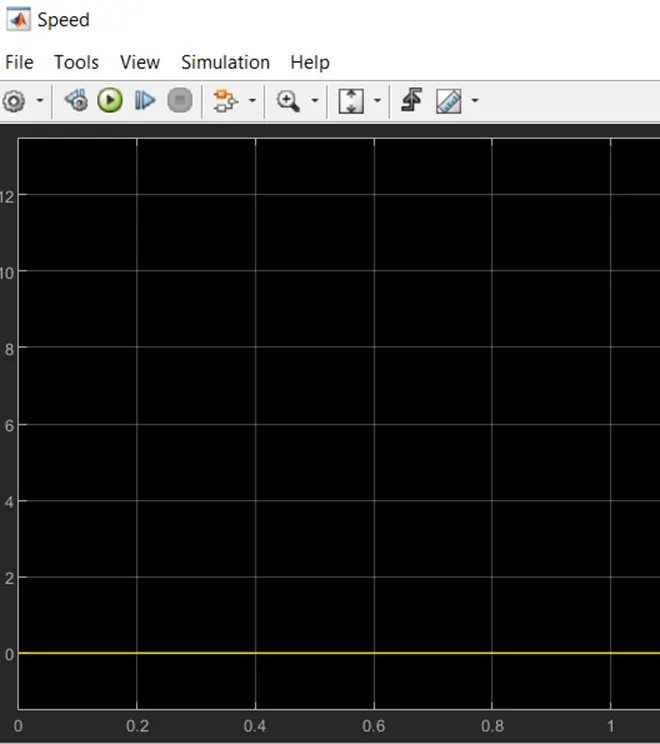
MIL Testing Result:
Software in Loop Testing:
Embedded code generation:
SIL Test Harness:
Result:
SIL Coverage:
7.Simulink Design Verifier
Error detection mode:
Error detection setting:
Compatibility Check:
Test Generation mode:
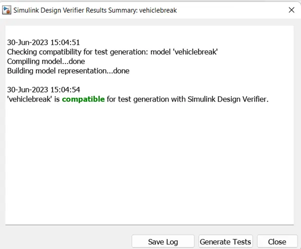
Compatibility check:
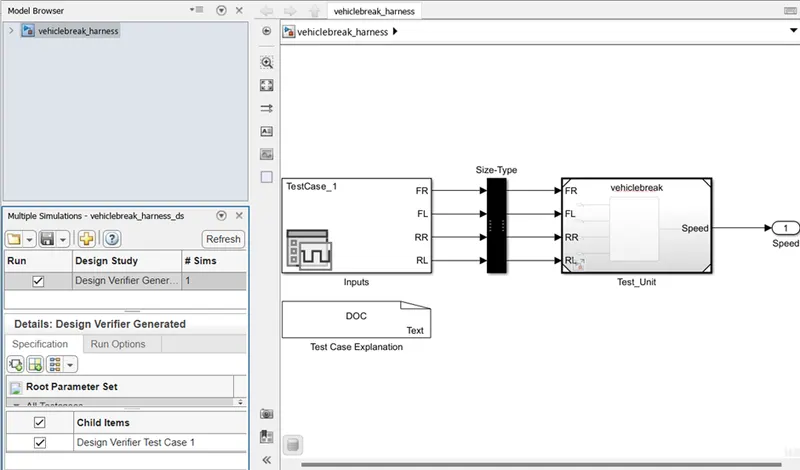
Test Harness generation:
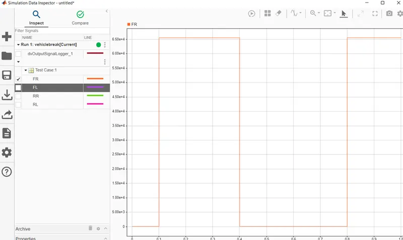
Data inspection:
9.Poly Space report:
Steps for Poly space Bug finder Analysis:
As we stated above it generate the bug report, code violation report and cod equality matrix reports.
Step1: Open the project, go to app and select the Polyspace static code analyser.
Step2: select the setting option and click on polyspace option for he window.
Step3: form the setting select setting from Project Configuration& MISRA C2004 setting. Input option use for minimum and maximum values. Tuneable parameter can be use calibration data. Set the output as No verification. Enable the check open verification result after verification.
Step4: in bug finder code configuration select the source code language as C or C++ as per the requirement.
Step5: next click to code standard and code matrix, form here select MISRA C or CERT C guideline as per industry standard use.
Step6: select bug finder analysis, based on run time error or code errors. We can also select it as default.
Step7: At last click on Run button, it will give the Analysis report. Also go to source code to find the error and we can check and correct it.
Steps to solve Polyspace code prover:
This code prover are use for overflow, divide by zero, out of boundary array access and other runtime errors detection. Here color coding is use to indicate the various errors.
Step1: Change the mode of Polyspace tool form Bug finder to Code proven.
Step2: select the code prover verification form the window and click the radio button to Enable it.
Step3: Run the analysis.
Step4: check the Analysis report, here green colour shows completely pass, red colour shows the error, also see the coverage report.
Step5: if any warning in red colour then click on that, it will open the code. Make correction and run repeatedly.
Result:
In this way we have use the Polyspace Code Analysis for the given model to find the Bug into the generated code and code prover also.
10.Simulink Test Manager:
Simulink model
Requirement Tagging:
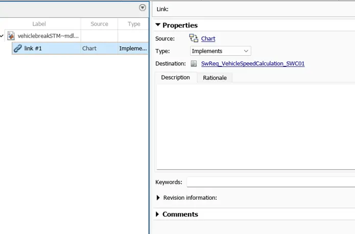
- A) Baseline Testing
New test case:
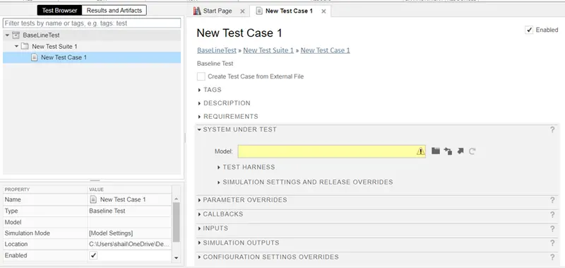
Requirement Adding:
Requirement Adding:
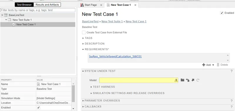
System under test:
Input setting:
Baseline Criteria:
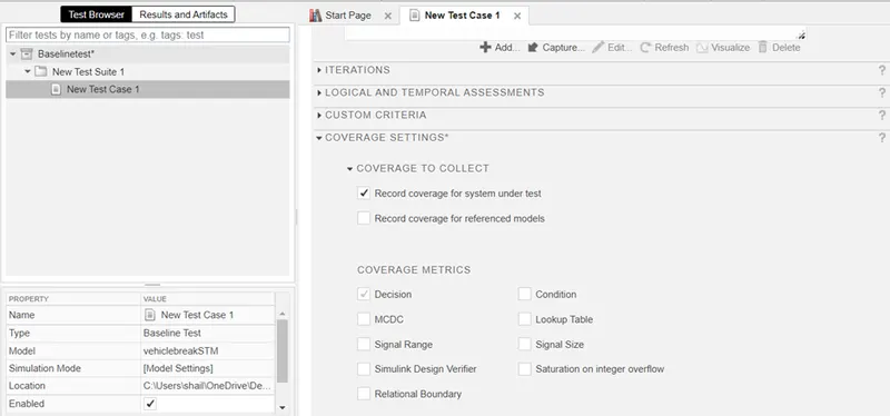
Coverage Setting:
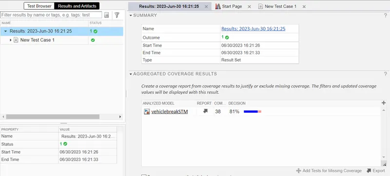
Result and Artifacts:
Back to Back Testing:
Add Test:
Select Design verifier:
Select Back to Back Testing:
Select path:
Test model component:
Requirement linking:
Simulation1:
Simulation2:
Equivalence criteria:
Coverage setting:
Results: