Project 2-Highway Assistant-Lane Changing Assistant
Objective -
To develop one specific requirement of Highway Assistant – Lane Changing Assistant algorithm.
- This model must be developed in MATLAB Simulink as per MBD guidelines.
- Simulink Data Dictionary must be created for the model & must be linked to the model.
- All the input & output signals must be mapped into the Autosar Editor.
- To generate Model Advisor Report.
- To generate code using Code Generation.
Highway Assistant (Lane Changing Assistant) -
- The Highway Assistant supports the driver and takes over the longitudinal and lateral guidance of the vehicle in monotonous driving situations on highways.
- The partially automated function can automatically start, accelerate, brake as well as steer the vehicle to a certain extent.
- The driver has to permanently supervise the system and be ready to take over the complete control of the vehicle at any time.
- Drivers are taught to assess surrounding traffic before changing lanes by checking their rearview and side mirrors and looking over each shoulder.
- However, even for those who follow this sequence of checks, the vehicle's blind spot – the area alongside and just behind the vehicle – is a constant source of danger and often the cause of serious accidents.
- Even vehicles approaching quickly from behind can pose a risk.
- To make changing lanes safer, this feature has been developed.
Basic Working Principle -
- Highway Assistant is a partially automated driving function for a speed range of up to 180 km/h (112 mph) on highways.
- It combines the radar-based longitudinal guidance of Adaptive Cruise Control (ACC) with the video-based lateral guidance of lane keeping support in one system.
- Highway Assistant can be supplemented by an automatic lane change initiated and monitored by the driver in a speed range of 60 – 130 km/h (35 – 80 mph).
- The lane Change Assistant works by using two mid-range radar sensors that are concealed in the rear bumper – one on the left, one on the right.
- These two sensors monitor the area alongside and behind the car.
- Powerful control software collates the sensor information to create a complete picture of all traffic in the area behind the vehicle.
- Whenever another vehicle approaches at speed from behind or is already present in the blind spot, a signal such as a warning light in the side mirror alerts the driver to the hazard.
- Should the driver still activate the turn signal with the intention of changing lanes, the system issues an additional acoustic and/or haptic warning.
Configuration Settings -
- Solver Setting -
- For the Autosar Complaint Model the solver should be Fixed Step Discrete solver.
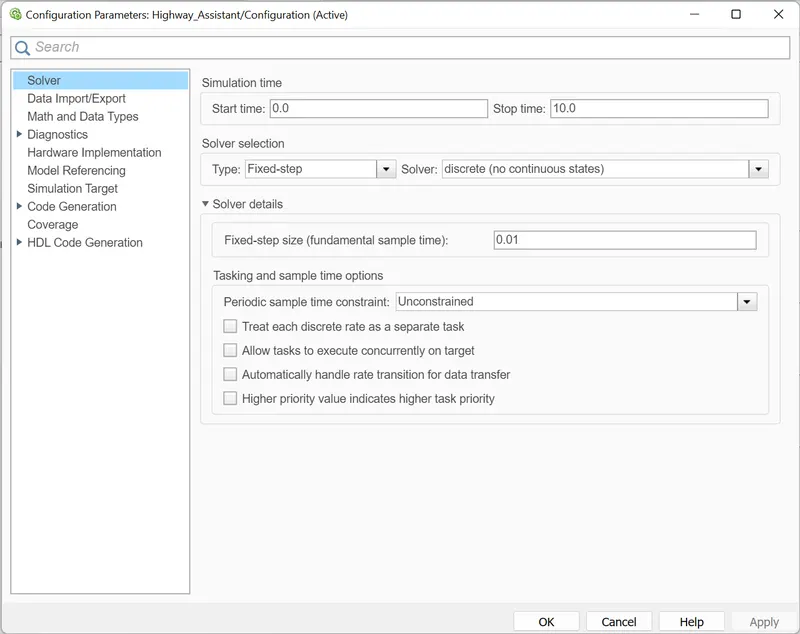
- For the Autosar Complaint Model the solver should be Fixed Step Discrete solver.
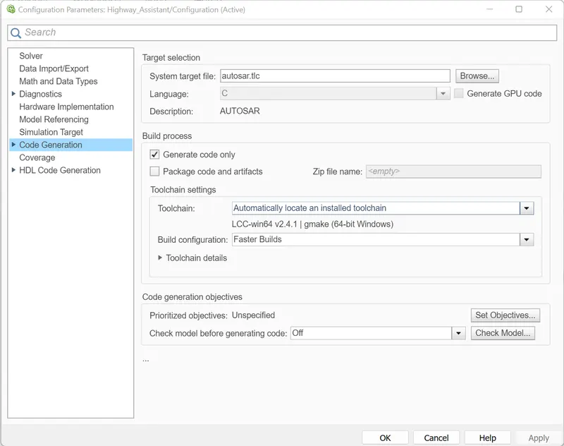
- Code Generation Setting -
- Autosar Coder is used to generate the code.
- The system file is autosar.tlc
Simulink Data Dictionary File -
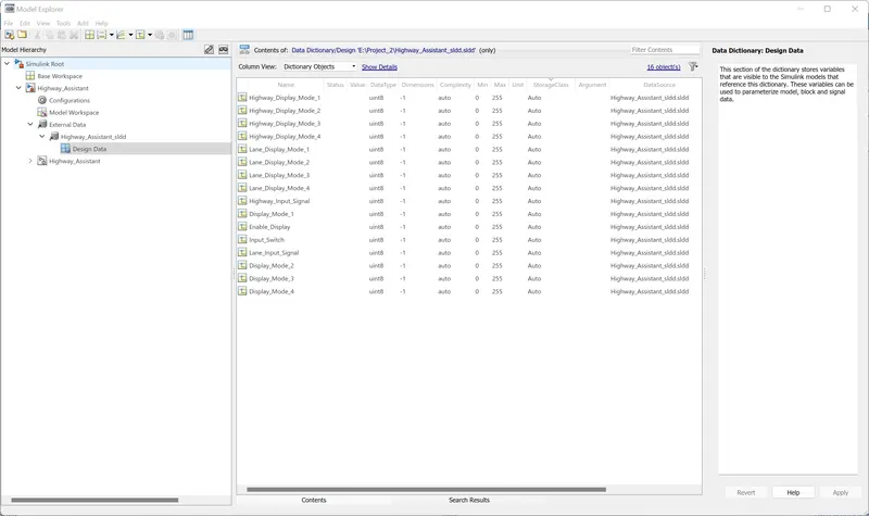
- Create a new sldd file and link it with the model.
- Make entries of the signals as given in the requirement document.
- The Storage Class is given Auto.
Model Development -
- Take a subsystem block for implementing the logic.
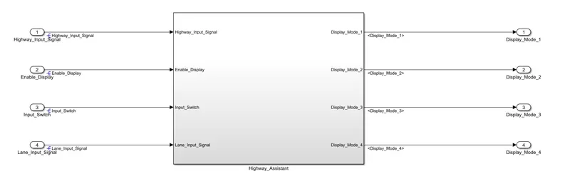
- Take a subsystem for each requirement.
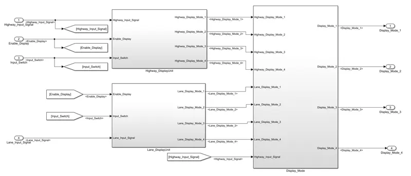
- For Requirement-1 Highway Display Unit,
- Inputs to this particular subsystem are “Highway_Input_Signal”, “Enable_Display”, “Input_Switch”.
- These three input signals, when assigned to a particular value will give output signals of specific value.
- The output signals are “Highway_Display_Mode_1”, “Highway_Display_Mode_2”, “Highway_Display_Mode_3”, “Highway_Display_Mode_4”.
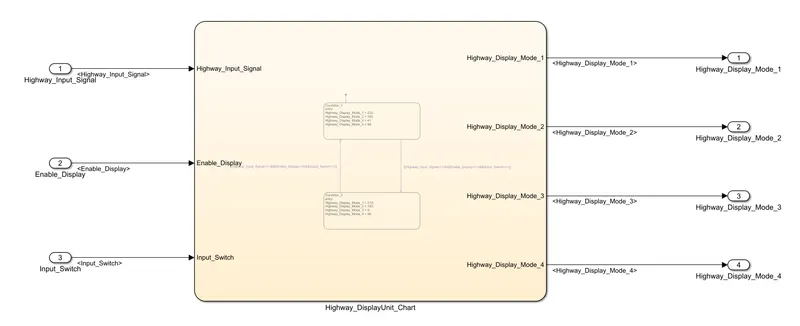
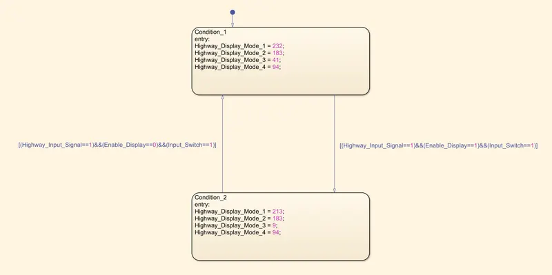
- The requirement must be implemented in the form of a Stateflow logic.
Condition Action Highway_Input_Signal = 1
Enable_Display = off
Input_Switch = on
Highway_Display_Mode_1 = 232
Highway_Display_Mode_2 = 183
Highway_Display_Mode_3 = 41
Highway_Display_Mode_4 = 94
Highway_Input_Signal = 1
Enable_Display = on
Input_Switch = on
Highway_Display_Mode_1 = 213
Highway_Display_Mode_2 = 183
Highway_Display_Mode_3 = 9
Highway_Display_Mode_4 = 94
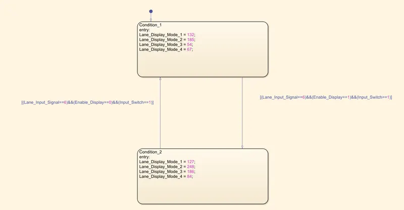
- For Requirement-2 Lane Display Unit,
- Inputs to this particular subsystem are “Enable_Display”, “Input_Switch”, “Lane_Input_Signal”.
- These three input signals, when assigned to a particular value will give output signals of specific value.
- The output signals are “Lane_Display_Mode_1”, “Lane_Display_Mode_2”, “Lane_Display_Mode_3”, “Lane_Display_Mode_4”.
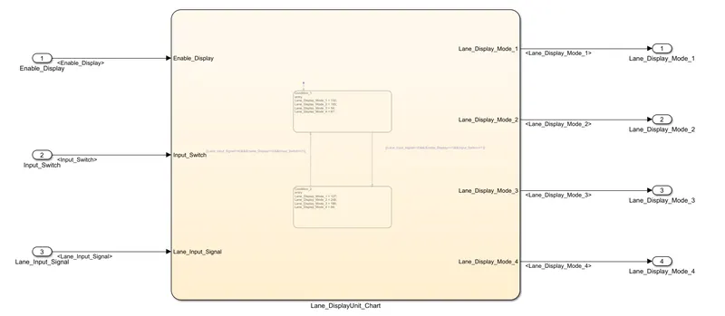
- The requirement must be implemented in the form of Stateflow logic.
Condition Action Lane_Input_Signal= 6
Enable_Display = off
Input_Switch = on
Lane_Display_Mode_1 = 132
Lane_Display_Mode_2 = 185
Lane_Display_Mode_3 = 54
Lane_Display_Mode_4 = 67
Lane_Input_Signal= 6
Enable_Display = on
Input_Switch = on
Lane_Display_Mode_1 = 127
Lane_Display_Mode_2 = 248
Lane_Display_Mode_3 = 186
Lane_Display_Mode_4 = 84
- For Requirement-3,
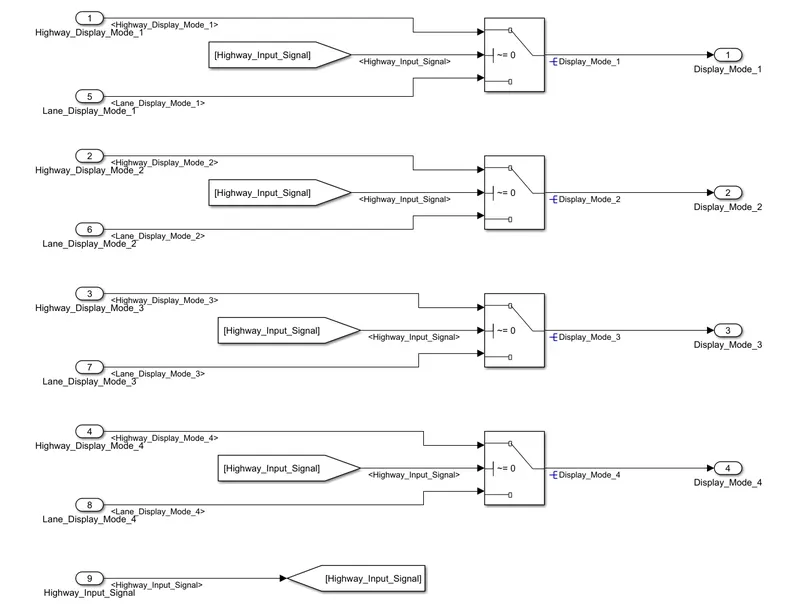
- Signals coming from both subsystems “Highway_Display_Mode_1” & “Lane_Display_Mode_1” are given as inputs to a switch block.
- “Highway_Input_Signal” is given as 2nd input to the switch block.
- Corresponding output from this particular switch block is output signal “Display_Mode_1”.
- Signals coming from both subsystems “Highway_Display_Mode_2” & “Lane_Display_Mode_2” are given as inputs to a switch block.
- “Highway_Input_Signal” is given as 2nd input to the switch block.
- Corresponding output from this particular switch block is output signal “Display_Mode_2”.
- Signals coming from both subsystems “Highway_Display_Mode_3” & “Lane_Display_Mode_3” are given as inputs to a switch block.
- “Highway_Input_Signal” is given as 2nd input to the switch block.
- Corresponding output from this particular switch block is output signal “Display_Mode_3”.
- Signals coming from both subsystems “Highway_Display_Mode_4” & “Lane_Display_Mode_4” are given as inputs to a switch block.
- “Highway_Input_Signal” is given as 2nd input to the switch block.
- Corresponding output from this particular switch block is output signal “Display_Mode_4”.
Requirements Tagging, Signal Resolving and Propagation -
- After developing the model tag the requirements to the Requirement Document.
- The tag will show under the requirements option.
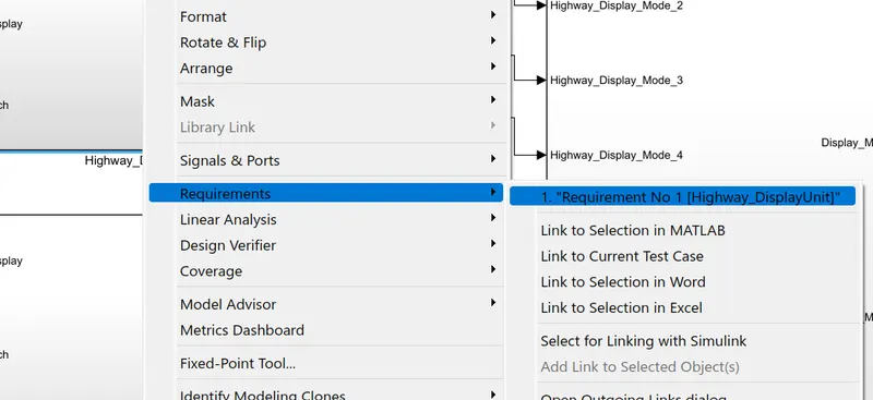
- This is done for all the requirements present in the requirement document.
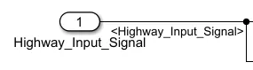
- All the signals must be resolved at the origin.
- After resolving the signal a blue symbol will appear in front of signal name.
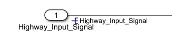
- The resolved signals should be propagated for the continuation of signal.
- The propagated signal name will appear between <> symbols.
Model Advisor Report -
- After developing the model, to check whether the developed model is as per the MAAB guidelines or not.
- For this Modelling Standards for MAAB check is done.
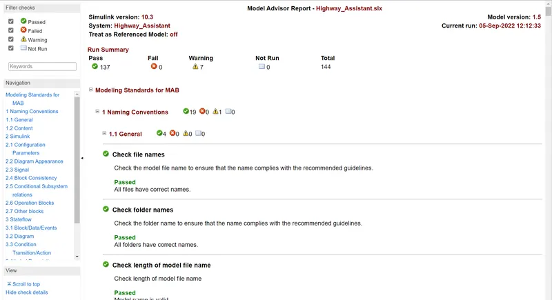
- There are 144 checks and after running these checks there should be no Fail condition.
- Reduce the warnings as much as possible.
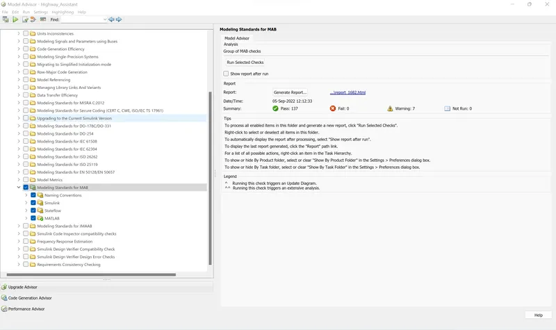
- Generate the model advisor report.
Autosar Port Mappings -
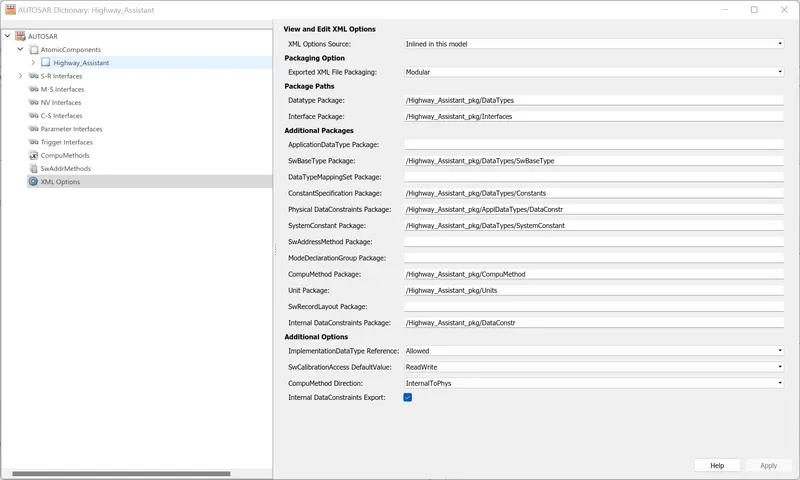
- Open the Autosar Component Designer from the APPS menu.
- Open the Autosar Dictionary from the Code Mappings.
- Select the XML options and add the paths for different packages.
- Add different SR Interfaces and use prefix "SRIF_" following with the signal name.
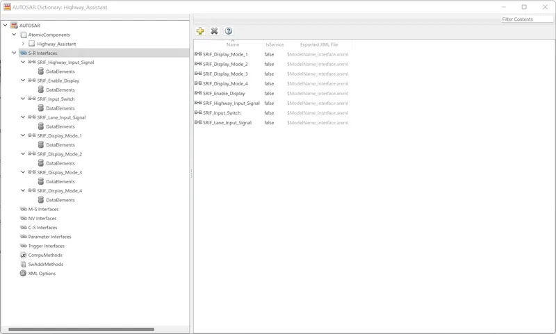
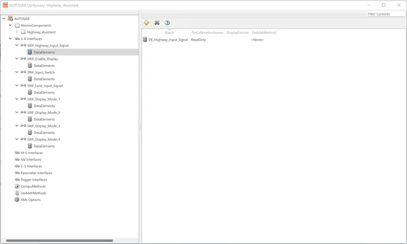
- Add corresponding data element to it using prefix "DE_" with signal name.
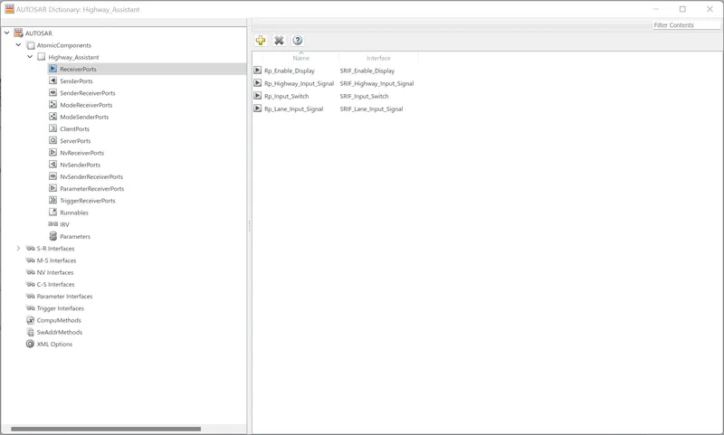
- Add the Receiver Ports with prefix "Rp_" with signal name and select the corresponding the SR Interface.
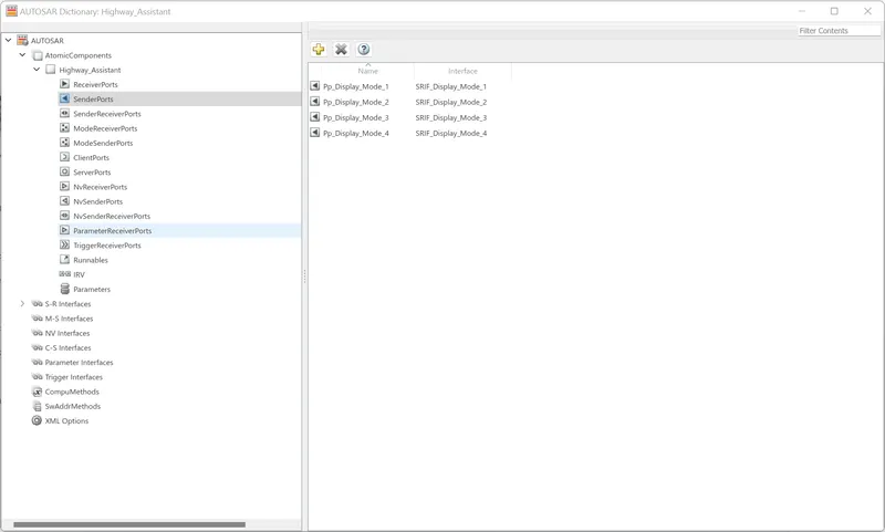
- Add the Sender Ports with prefix "Pp_" with signal name and select the corresponding the SR Interface.
- In the Runnables section, create two events - one timing event and one initialize event.
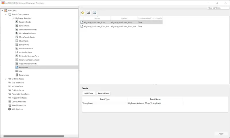
- Click Apply after creating the events.
- In the Code Mappings, select the corresponding events for Functions.

- And select the corresponding Receiver Ports and Data Elements for Inports.

- Also select the corresponding Sender Ports and Data Elements for Outports.

- Validate the settings by clicking on the tick sign.
Code Generation -
- To generate the code click on Generate Code option.
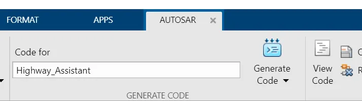
- After Code is generated, it is shown in the tab appear in the right hand side of window.

Code -
File: Highway_Assistant.c
1	/*
2	 * File: Highway_Assistant.c
3	 *
4	 * Code generated for Simulink model 'Highway_Assistant'.
5	 *
6	 * Model version                  : 1.6
7	 * Simulink Coder version         : 9.5 (R2021a) 14-Nov-2020
8	 * C/C++ source code generated on : Mon Sep  5 12:56:03 2022
9	 *
10	 * Target selection: autosar.tlc
11	 * Embedded hardware selection: Intel->x86-64 (Windows64)
12	 * Code generation objectives: Unspecified
13	 * Validation result: Not run
14	 */
15
16	#include "Highway_Assistant.h"
17	#include "Highway_Assistant_private.h"
18
19	/* Named constants for Chart: '/Highway_DisplayUnit_Chart' */
20	#define Highway_Assistan_IN_Condition_1 ((uint8)1U)
21	#define Highway_Assistan_IN_Condition_2 ((uint8)2U)
22
23	/* Block states (default storage) */
24	DW_Highway_Assistant_T Highway_Assistant_DW;
25
26	/* Model step function */
27	void Highway_Assistant_50ms(void)
28	{
29	  sint32 tmp;
30	  uint8 rtb_Highway_Display_Mode_1;
31	  uint8 rtb_Highway_Display_Mode_3;
32	  uint8 rtb_Lane_Display_Mode_1;
33	  uint8 rtb_Lane_Display_Mode_2;
34	  uint8 rtb_Lane_Display_Mode_3;
35	  uint8 rtb_Lane_Display_Mode_4;
36
37	  /* Chart: '/Highway_DisplayUnit_Chart' incorporates:
38	   *  Inport: '/Enable_Display'
39	   *  Inport: '/Highway_Input_Signal'
40	   *  Inport: '/Input_Switch'
41	   */
42	  if (Highway_Assistant_DW.is_active_c3_Highway_Assistant == 0U) {
43	    Highway_Assistant_DW.is_active_c3_Highway_Assistant = 1U;
44	    Highway_Assistant_DW.is_c3_Highway_Assistant =
45	      Highway_Assistan_IN_Condition_1;
46	    rtb_Highway_Display_Mode_1 = 232U;
47	    rtb_Highway_Display_Mode_3 = 41U;
48	  } else if (Highway_Assistant_DW.is_c3_Highway_Assistant ==
49	             Highway_Assistan_IN_Condition_1) {
50	    rtb_Highway_Display_Mode_1 = 232U;
51	    rtb_Highway_Display_Mode_3 = 41U;
52	    if ((Rte_IRead_Highway_Assistant_50ms_Rp_Highway_Input_Signal_DE_Highway_Input_Signal
53	         () == 1) &&
54	        (Rte_IRead_Highway_Assistant_50ms_Rp_Enable_Display_DE_Enable_Display() ==
55	         1) && (Rte_IRead_Highway_Assistant_50ms_Rp_Input_Switch_DE_Input_Switch
56	                () == 1)) {
57	      Highway_Assistant_DW.is_c3_Highway_Assistant =
58	        Highway_Assistan_IN_Condition_2;
59	      rtb_Highway_Display_Mode_1 = 213U;
60	      rtb_Highway_Display_Mode_3 = 9U;
61	    }
62	  } else {
63	    /* case IN_Condition_2: */
64	    rtb_Highway_Display_Mode_1 = 213U;
65	    rtb_Highway_Display_Mode_3 = 9U;
66	    if ((Rte_IRead_Highway_Assistant_50ms_Rp_Highway_Input_Signal_DE_Highway_Input_Signal
67	         () == 1) &&
68	        (Rte_IRead_Highway_Assistant_50ms_Rp_Enable_Display_DE_Enable_Display() ==
69	         0) && (Rte_IRead_Highway_Assistant_50ms_Rp_Input_Switch_DE_Input_Switch
70	                () == 1)) {
71	      Highway_Assistant_DW.is_c3_Highway_Assistant =
72	        Highway_Assistan_IN_Condition_1;
73	      rtb_Highway_Display_Mode_1 = 232U;
74	      rtb_Highway_Display_Mode_3 = 41U;
75	    }
76	  }
77
78	  /* End of Chart: '/Highway_DisplayUnit_Chart' */
79
80	  /* Chart: '/Lane_DisplayUnit_Chart' incorporates:
81	   *  Inport: '/Enable_Display'
82	   *  Inport: '/Input_Switch'
83	   *  Inport: '/Lane_Input_Signal'
84	   */
85	  if (Highway_Assistant_DW.is_active_c1_Highway_Assistant == 0U) {
86	    Highway_Assistant_DW.is_active_c1_Highway_Assistant = 1U;
87	    Highway_Assistant_DW.is_c1_Highway_Assistant =
88	      Highway_Assistan_IN_Condition_1;
89	    rtb_Lane_Display_Mode_1 = 132U;
90	    rtb_Lane_Display_Mode_2 = 185U;
91	    rtb_Lane_Display_Mode_3 = 54U;
92	    rtb_Lane_Display_Mode_4 = 67U;
93	  } else if (Highway_Assistant_DW.is_c1_Highway_Assistant ==
94	             Highway_Assistan_IN_Condition_1) {
95	    rtb_Lane_Display_Mode_1 = 132U;
96	    rtb_Lane_Display_Mode_2 = 185U;
97	    rtb_Lane_Display_Mode_3 = 54U;
98	    rtb_Lane_Display_Mode_4 = 67U;
99	    if ((Rte_IRead_Highway_Assistant_50ms_Rp_Lane_Input_Signal_DE_Lane_Input_Signal
100	         () == 6) &&
101	        (Rte_IRead_Highway_Assistant_50ms_Rp_Enable_Display_DE_Enable_Display() ==
102	         1) && (Rte_IRead_Highway_Assistant_50ms_Rp_Input_Switch_DE_Input_Switch
103	                () == 1)) {
104	      Highway_Assistant_DW.is_c1_Highway_Assistant =
105	        Highway_Assistan_IN_Condition_2;
106	      rtb_Lane_Display_Mode_1 = 127U;
107	      rtb_Lane_Display_Mode_2 = 248U;
108	      rtb_Lane_Display_Mode_3 = 186U;
109	      rtb_Lane_Display_Mode_4 = 84U;
110	    }
111	  } else {
112	    /* case IN_Condition_2: */
113	    rtb_Lane_Display_Mode_1 = 127U;
114	    rtb_Lane_Display_Mode_2 = 248U;
115	    rtb_Lane_Display_Mode_3 = 186U;
116	    rtb_Lane_Display_Mode_4 = 84U;
117	    if ((Rte_IRead_Highway_Assistant_50ms_Rp_Lane_Input_Signal_DE_Lane_Input_Signal
118	         () == 6) &&
119	        (Rte_IRead_Highway_Assistant_50ms_Rp_Enable_Display_DE_Enable_Display() ==
120	         0) && (Rte_IRead_Highway_Assistant_50ms_Rp_Input_Switch_DE_Input_Switch
121	                () == 1)) {
122	      Highway_Assistant_DW.is_c1_Highway_Assistant =
123	        Highway_Assistan_IN_Condition_1;
124	      rtb_Lane_Display_Mode_1 = 132U;
125	      rtb_Lane_Display_Mode_2 = 185U;
126	      rtb_Lane_Display_Mode_3 = 54U;
127	      rtb_Lane_Display_Mode_4 = 67U;
128	    }
129	  }
130
131	  /* End of Chart: '/Lane_DisplayUnit_Chart' */
132
133	  /* Switch: '/Switch' incorporates:
134	   *  Inport: '/Highway_Input_Signal'
135	   *  Switch: '/Switch1'
136	   *  Switch: '/Switch2'
137	   */
138	  tmp =
139	    Rte_IRead_Highway_Assistant_50ms_Rp_Highway_Input_Signal_DE_Highway_Input_Signal
140	    ();
141	  if (tmp != 0) {
142	    /* Outport: '/Display_Mode_1' */
143	    Rte_IWrite_Highway_Assistant_50ms_Pp_Display_Mode_1_DE_Display_Mode_1
144	      (rtb_Highway_Display_Mode_1);
145	    rtb_Lane_Display_Mode_2 = 183U;
146	  } else {
147	    /* Outport: '/Display_Mode_1' */
148	    Rte_IWrite_Highway_Assistant_50ms_Pp_Display_Mode_1_DE_Display_Mode_1
149	      (rtb_Lane_Display_Mode_1);
150	  }
151
152	  /* End of Switch: '/Switch' */
153
154	  /* Outport: '/Display_Mode_2' */
155	  Rte_IWrite_Highway_Assistant_50ms_Pp_Display_Mode_2_DE_Display_Mode_2
156	    (rtb_Lane_Display_Mode_2);
157
158	  /* Switch: '/Switch2' incorporates:
159	   *  Switch: '/Switch3'
160	   */
161	  if (tmp != 0) {
162	    /* Outport: '/Display_Mode_3' */
163	    Rte_IWrite_Highway_Assistant_50ms_Pp_Display_Mode_3_DE_Display_Mode_3
164	      (rtb_Highway_Display_Mode_3);
165	    rtb_Lane_Display_Mode_4 = 94U;
166	  } else {
167	    /* Outport: '/Display_Mode_3' */
168	    Rte_IWrite_Highway_Assistant_50ms_Pp_Display_Mode_3_DE_Display_Mode_3
169	      (rtb_Lane_Display_Mode_3);
170	  }
171
172	  /* Outport: '/Display_Mode_4' */
173	  Rte_IWrite_Highway_Assistant_50ms_Pp_Display_Mode_4_DE_Display_Mode_4
174	    (rtb_Lane_Display_Mode_4);
175	}
176
177	/* Model initialize function */
178	void Highway_Assistant_50ms_Init(void)
179	{
180	  /* (no initialization code required) */
181	}
182
183	/*
184	 * File trailer for generated code.
185	 *
186	 * [EOF]
187	 */
188
Result -
- The model is developed as per the MAAB guidelines.
- The Model Advisor Check is done for this model.
- The Ports are mapped in the Autosar Dictionary.
- The code is generated using Autosar Coder.
Google Drive Link for this project https://drive.google.com/file/d/12PPu_fZoBBk2ww3s4FoaM2BXp8_P6Lqs/view?usp=sharing