Project 2-Highway Assistant-Lane Changing Assistant
---------------------------------------Chennai Skill Centre----------------------------------------------------
Problem Statement:
To develop one specific requirement of Highway Assistant – Lane Changing Assistant algorithm. Please note that the whole Highway Assistant – Lane Changing Assistant is a very huge algorithm & only one small part of the logic is implemented here. Idea is to familiarize with concepts of Autosar Software Component Development in MATLAB Environment by following the Model Based Development guidelines. The Project must be done keeping in mind the following processes & steps.
- This model must be developed in MATLAB Simulink per MBD guidelines.
- Code Generation Profile must be Autosar Coder.
- Simulink Data Dictionary must be created for the model & must be linked to the model.
- All the input & output signals must be mapped into the Autosar Editor.
- Model Advisor Report is mandatory & this will be followed by Code Generation.
Answers:-
The simulink model for the given problem statement has been shown below.
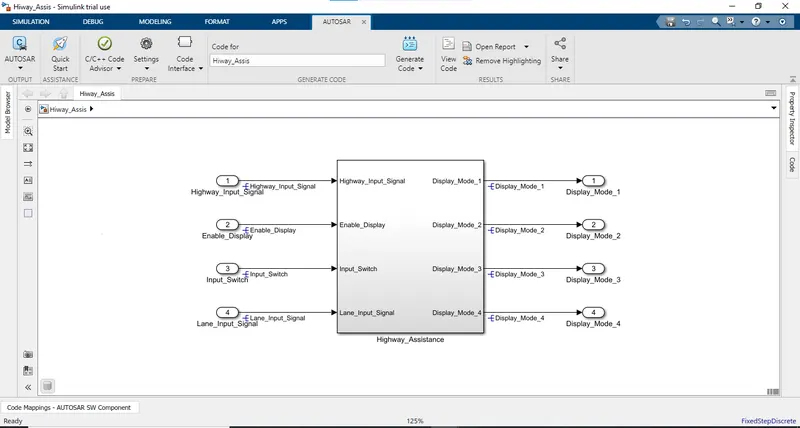
*The problem statement model was divided basically into three requirements Requirements 1,2 and 3 the requirements one and two were created using stae flo logics that were given in the question itself.
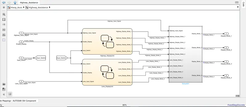
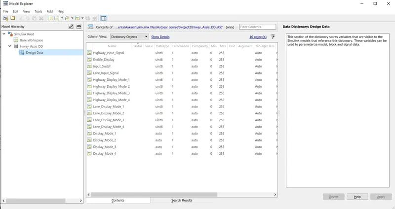
*Given inputs and output signals along with the local signal that are needed to be added into the data dictionary.
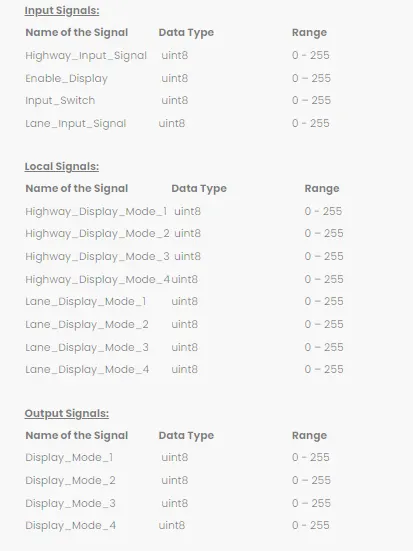
*Simulink Data Dictionary created for the simulink model.
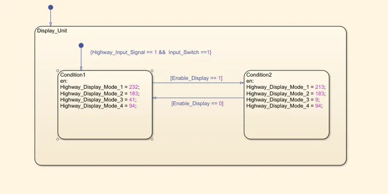
*The below shown image is of the state flow logic that is present in the requirement one staeflow chart. The requirement 1 is also given below
Requirement No 1 [Highway_DisplayUnit]:
Inputs to this particular subsystem are “Highway_Input_Signal”, “Enable_Display”, “Input_Switch”. These three input signals, when assigned to a particular value will give output signals of specific value. The output signals are “Highway_Display_Mode_1”, “Highway_Display_Mode_2”, “Highway_Display_Mode_3”, “Highway_Display_Mode_4”. The requirement must be implemented in the form of a Stateflow logic.
|
Condition |
Action |
|
Highway_Input_Signal = 1 Enable_Display = off Input_Switch = on |
Highway_Display_Mode_1 = 232 Highway_Display_Mode_2 = 183 Highway_Display_Mode_3 = 41 Highway_Display_Mode_4 = 94 |
|
Highway_Input_Signal = 1 Enable_Display = on Input_Switch = on |
Highway_Display_Mode_1 = 213 Highway_Display_Mode_2 = 183 Highway_Display_Mode_3 = 9 Highway_Display_Mode_4 = 94 |
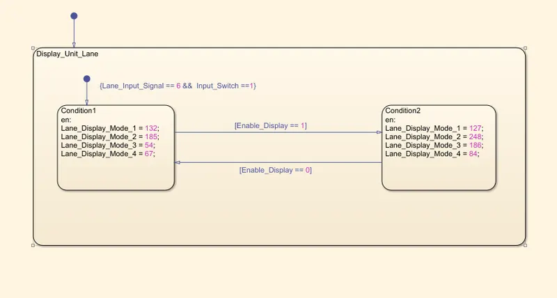
*The requirement 2 was also made using a state flow logic that comprised of similar processes that have been depicted below
Requirement No 2 [Lane_DisplayUnit]:
Inputs to this particular subsystem are “Enable_Display”, “Input_Switch”, “Lane_Input_Signal”. These three input signals, when assigned to a particular value will give output signals of specific value. The output signals are “Lane_Display_Mode_1”, “Lane_Display_Mode_2”, “Lane_Display_Mode_3”, “Lane_Display_Mode_4”. The requirement must be implemented in the form of Stateflow logic.
|
Condition |
Action |
|
Lane_Input_Signal= 6 Enable_Display = off Input_Switch = on |
Lane_Display_Mode_1 = 132 Lane_Display_Mode_2 = 185 Lane_Display_Mode_3 = 54 Lane_Display_Mode_4 = 67 |
|
Lane_Input_Signal= 6 Enable_Display = on Input_Switch = on |
Lane_Display_Mode_1 = 127 Lane_Display_Mode_2 = 248 Lane_Display_Mode_3 = 186 Lane_Display_Mode_4 = 84 |
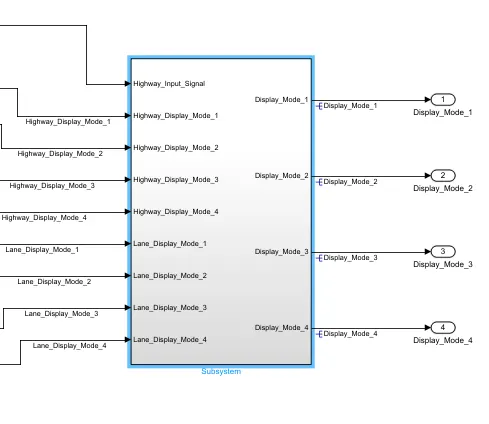
*The below shown image depicts the subsystem designed for the third requirement that is the for the Display mode requirement that will generate the output siganls for the model.
Requirement No 3:
Signals coming from both subsystems “Highway_Display_Mode_1” & “Lane_Display_Mode_1” are given as inputs to a switch block which will have input signal “Highway_Input_Signal” given as 2nd input to the switch block. Corresponding output from this particular switch block is output signal “Display_Mode_1”.
Signals coming from both subsystems “Highway_Display_Mode_2” & “Lane_Display_Mode_2” are given as inputs to a switch block which will have input signal “Highway_Input_Signal” given as 2nd input to the switch block. Corresponding output from this particular switch block is output signal “Display_Mode_2”.
Signals coming from both subsystems “Highway_Display_Mode_3” & “Lane_Display_Mode_3” are given as inputs to a switch block which will have input signal “Highway_Input_Signal” given as 2nd input to the switch block. Corresponding output from this particular switch block is output signal “Display_Mode_3”.
Signals coming from both subsystems “Highway_Display_Mode_4” & “Lane_Display_Mode_4” are given as inputs to a switch block which will have input signal “Highway_Input_Signal” given as 2nd input to the switch block. Corresponding output from this particular switch block is output signal “Display_Mode_4”.
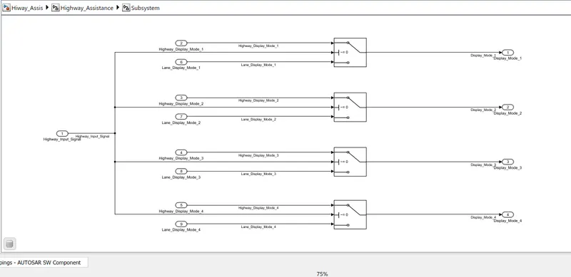
*After developing and compiling the model our next task was to generate the autosar complaint code for our model for which we started by changing the solver configurations from a variable step solver to a fixed step discrete with non continuous steps.
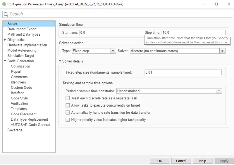
*After which one of the major changes that we did was to change the system target file in the code generation settings from grt.tlc to autosar.tlc in order to generate the autosar complaint code for our model.
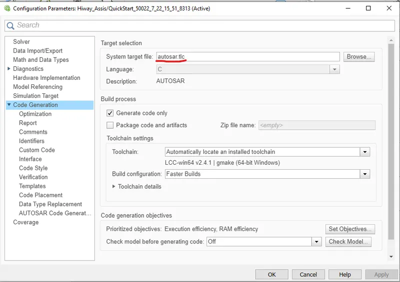
*But before generating the autosar complaint code we needed to add all the input and output signals as receiver and sender ports along with the SR interfaces and the respectivetive data elements for all the signals along with the changes in the XML Options was also to be done.
*Inside the autosar components app we clicked on the pop up tab shown below to enter into the Autosar Library were we can add all the required ports and interfaces that were mentioned above.
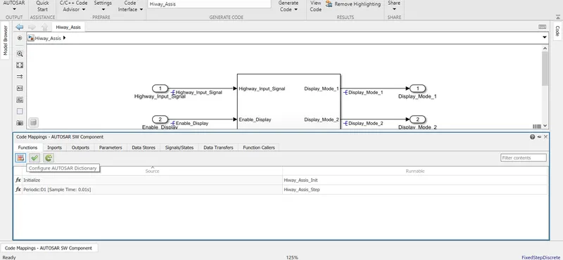
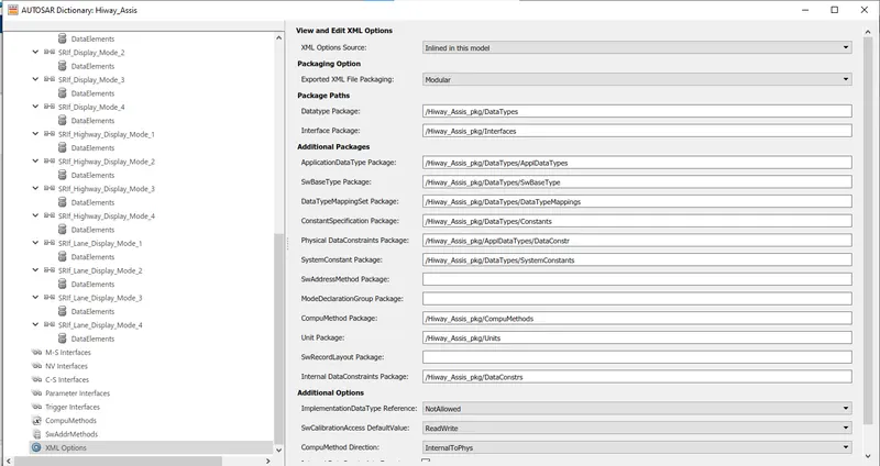
*The below image shows the veiw of the XML Options that we edited before adding the ports and interfaces into the autosar library,
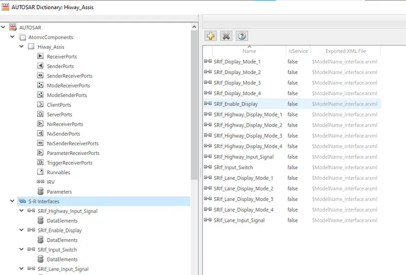
*For the S-R Interfaces of the model, we will rename the port with the prefix SRIf_
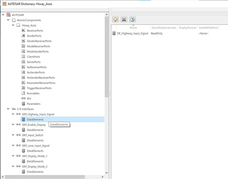
*For the Data Elements of the model, we will rename the port with the prefix DE_.
*The input signal that were provided to us were added as the reciever ports in the autosar dictionary
Input Signals:
|
Name of the Signal |
Data Type |
Range |
|
Highway_Input_Signal |
uint8 |
0 - 255 |
|
Enable_Display |
uint8 |
0 – 255 |
|
Input_Switch |
uint8 |
0 – 255 |
|
Lane_Input_Signal |
uint8 |
0 - 255 |
*For the Reciever port of the model, that is input, we will rename the port with the prefix Rp_
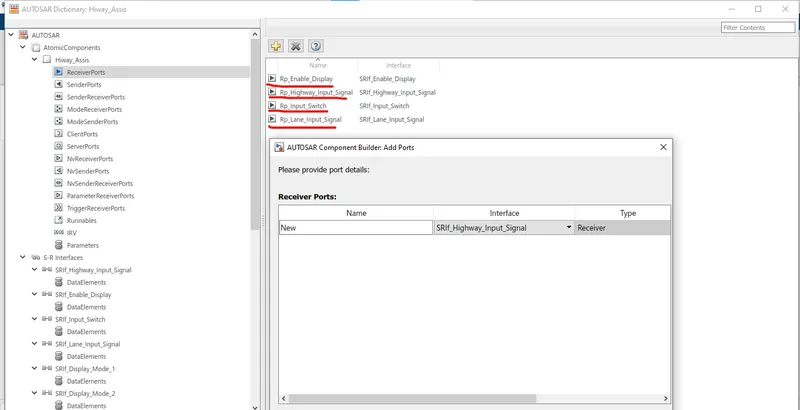
*The interface signals for the respective reciever ports were selected in the drop down box that had all the interfaces listed.
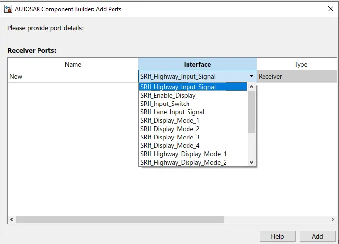
*The output signals that were provided to us were added as the sender ports in the autosar dictionary
Output Signals:
|
Name of the Signal |
Data Type |
Range |
|
Display_Mode_1 |
uint8 |
0 - 255 |
|
Display_Mode_2 |
uint8 |
0 – 255 |
|
Display_Mode_3 |
uint8 |
0 – 255 |
|
Display_Mode_4 |
uint8 |
0 - 255 |
*For the Sender port of the model, that is output, we will rename the port with the prefix Pp_.
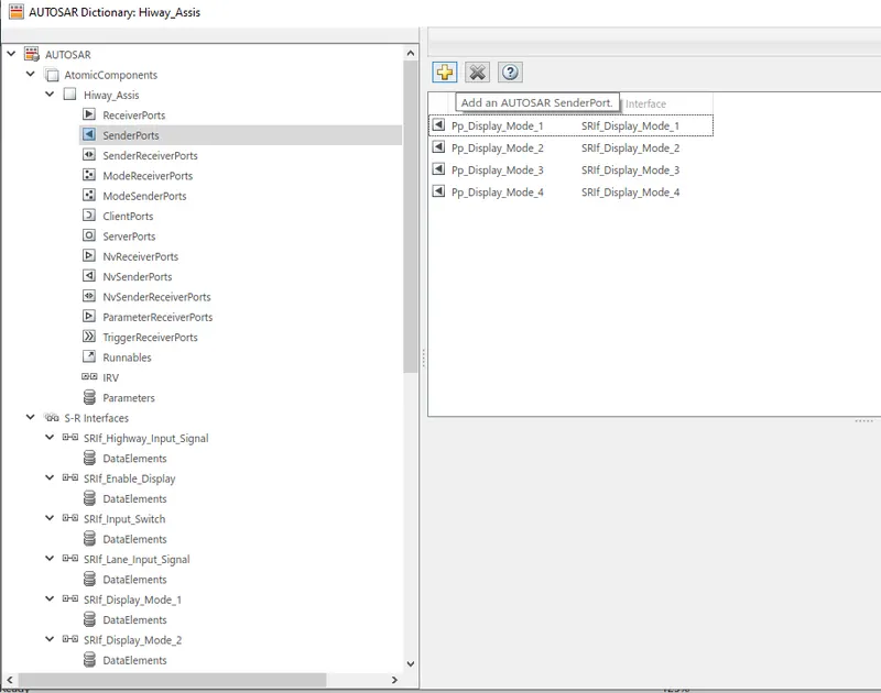
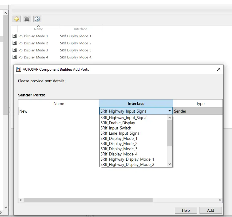
*The interface signals for the respective sender ports were selected in the drop down box that had all the interfaces listed.
*Now we start mapping the inputs signal in the autosar component window mapping the ports along with their respective elements.
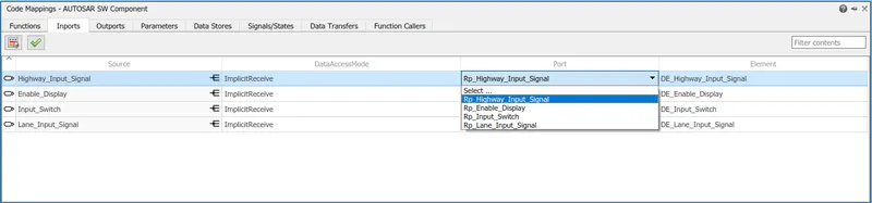
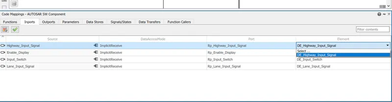
*Now we start mapping the inputs signal in the autosar component window mapping the ports along with their respective elements.
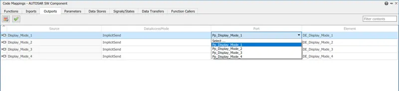
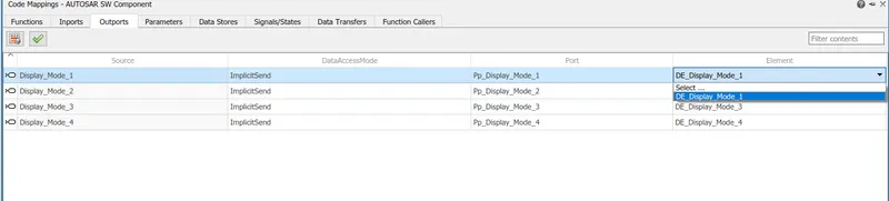
*After mapping all thye signals we update the autosar window by clicking the below depicted refresh code mappings.
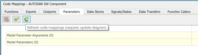
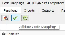
*After updating the mappings we now finally validate the mapping by clicking the green tick icon
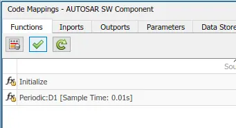
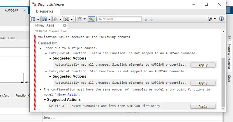
*While compiling the model simulink popped up with certain errors were it was prompting us to map all the unmapped simulink elements to Autosar properties and an apply option was then clicked to remove the errors.
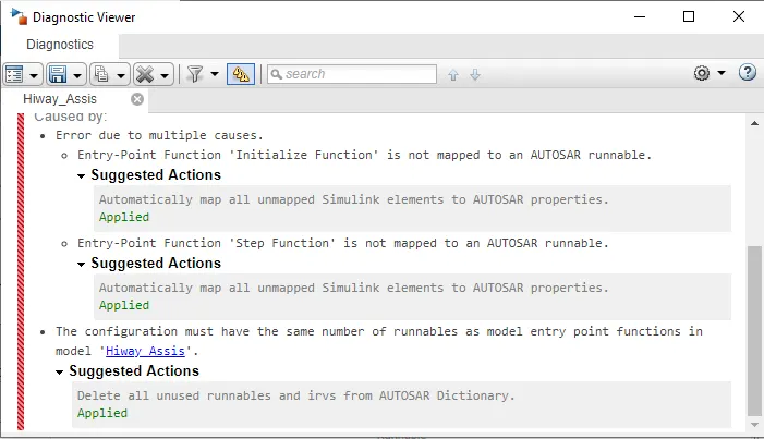
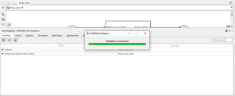
*The final step that we did was to validate the model code mappings which when done successfully gave us a message telling that the validation was successful.
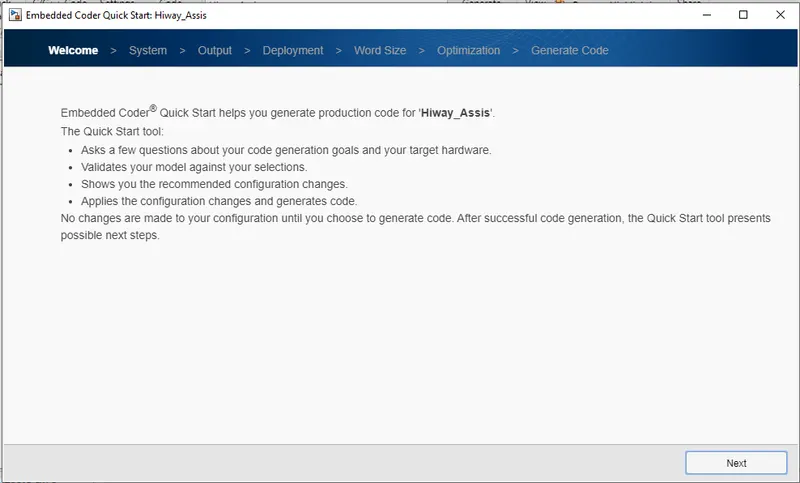
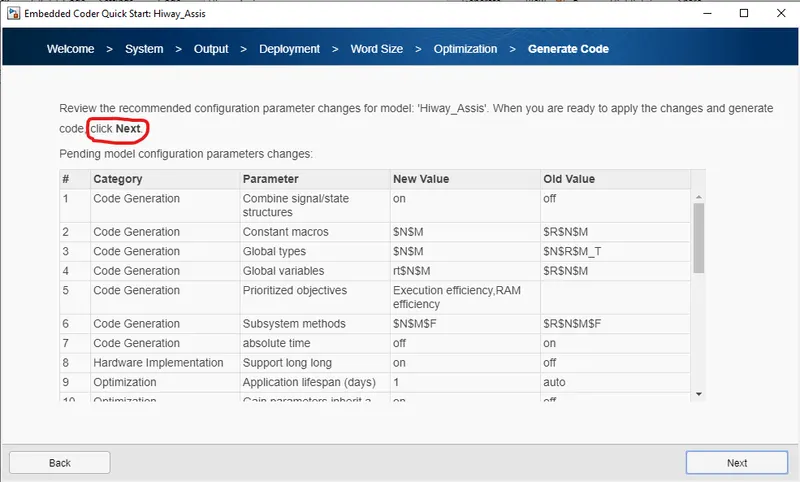
 *After the validation is complete we now move on to the code generation part by clicking on the quick start icon(shown on the left) on the top left corner of the simulink window.
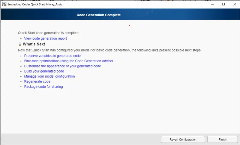
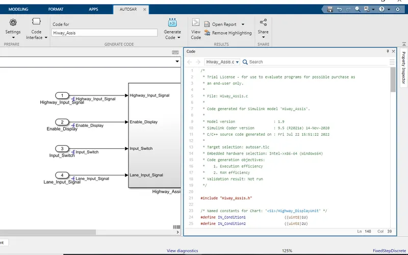
*Code generation report
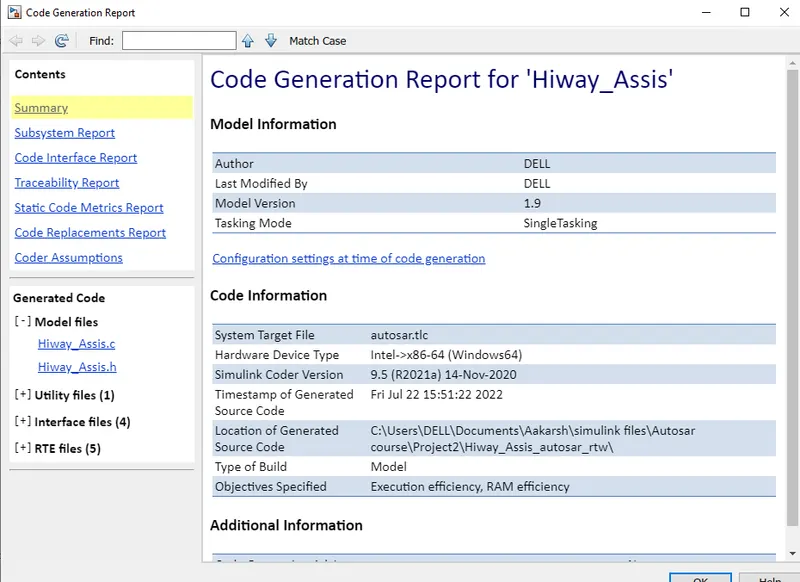
*The generated Autosar Complaint code.
/*
 * Trial License - for use to evaluate programs for possible purchase as
 * an end-user only.
 *
 * File: Hiway_Assis.c
 *
 * Code generated for Simulink model 'Hiway_Assis'.
 *
 * Model version                  : 1.9
 * Simulink Coder version         : 9.5 (R2021a) 14-Nov-2020
 * C/C++ source code generated on : Fri Jul 22 15:51:22 2022
 *
 * Target selection: autosar.tlc
 * Embedded hardware selection: Intel->x86-64 (Windows64)
 * Code generation objectives:
 *    1. Execution efficiency
 *    2. RAM efficiency
 * Validation result: Not run
 */

#include "Hiway_Assis.h"

/* Named constants for Chart: '/Highway_DisplayUnit' */
#define IN_Condition1                  ((uint8)1U)
#define IN_Condition2                  ((uint8)2U)

/* Block signals and states (default storage) */
DW rtDW;

/* Model step function */
void Hiway_Assis_Step(void)
{
  sint32 rtb_Highway_Display_Mode_1;
  sint32 rtb_Highway_Display_Mode_3;
  sint32 rtb_Lane_Display_Mode_1;
  sint32 rtb_Lane_Display_Mode_2;
  sint32 rtb_Lane_Display_Mode_3;
  sint32 rtb_Lane_Display_Mode_4;
  sint32 tmp;

  /* Chart: '/Highway_DisplayUnit' incorporates:
   *  Inport: '/Enable_Display'
   */
  if (rtDW.is_active_c3_Hiway_Assis == 0U) {
    rtDW.is_active_c3_Hiway_Assis = 1U;
    rtDW.is_Display_Unit = IN_Condition1;
    rtb_Highway_Display_Mode_1 = 232;
    rtb_Highway_Display_Mode_3 = 41;
  } else if (rtDW.is_Display_Unit == IN_Condition1) {
    rtb_Highway_Display_Mode_1 = 232;
    rtb_Highway_Display_Mode_3 = 41;
    if (Rte_IRead_Hiway_Assis_Step_Rp_Enable_Display_DE_Enable_Display() == 1) {
      rtDW.is_Display_Unit = IN_Condition2;
      rtb_Highway_Display_Mode_1 = 213;
      rtb_Highway_Display_Mode_3 = 9;
    }
  } else {
    /* case IN_Condition2: */
    rtb_Highway_Display_Mode_1 = 213;
    rtb_Highway_Display_Mode_3 = 9;
    if (Rte_IRead_Hiway_Assis_Step_Rp_Enable_Display_DE_Enable_Display() == 0) {
      rtDW.is_Display_Unit = IN_Condition1;
      rtb_Highway_Display_Mode_1 = 232;
      rtb_Highway_Display_Mode_3 = 41;
    }
  }

  /* End of Chart: '/Highway_DisplayUnit' */

  /* Chart: '/Lane_DisplayUnit' incorporates:
   *  Inport: '/Enable_Display'
   */
  if (rtDW.is_active_c1_Hiway_Assis == 0U) {
    rtDW.is_active_c1_Hiway_Assis = 1U;
    rtDW.is_Display_Unit_Lane = IN_Condition1;
    rtb_Lane_Display_Mode_1 = 132;
    rtb_Lane_Display_Mode_2 = 185;
    rtb_Lane_Display_Mode_3 = 54;
    rtb_Lane_Display_Mode_4 = 67;
  } else if (rtDW.is_Display_Unit_Lane == IN_Condition1) {
    rtb_Lane_Display_Mode_1 = 132;
    rtb_Lane_Display_Mode_2 = 185;
    rtb_Lane_Display_Mode_3 = 54;
    rtb_Lane_Display_Mode_4 = 67;
    if (Rte_IRead_Hiway_Assis_Step_Rp_Enable_Display_DE_Enable_Display() == 1) {
      rtDW.is_Display_Unit_Lane = IN_Condition2;
      rtb_Lane_Display_Mode_1 = 127;
      rtb_Lane_Display_Mode_2 = 248;
      rtb_Lane_Display_Mode_3 = 186;
      rtb_Lane_Display_Mode_4 = 84;
    }
  } else {
    /* case IN_Condition2: */
    rtb_Lane_Display_Mode_1 = 127;
    rtb_Lane_Display_Mode_2 = 248;
    rtb_Lane_Display_Mode_3 = 186;
    rtb_Lane_Display_Mode_4 = 84;
    if (Rte_IRead_Hiway_Assis_Step_Rp_Enable_Display_DE_Enable_Display() == 0) {
      rtDW.is_Display_Unit_Lane = IN_Condition1;
      rtb_Lane_Display_Mode_1 = 132;
      rtb_Lane_Display_Mode_2 = 185;
      rtb_Lane_Display_Mode_3 = 54;
      rtb_Lane_Display_Mode_4 = 67;
    }
  }

  /* End of Chart: '/Lane_DisplayUnit' */

  /* Switch: '/Switch' incorporates:
   *  Inport: '/Highway_Input_Signal'
   *  Switch: '/Switch1'
   *  Switch: '/Switch2'
   */
  tmp =
    Rte_IRead_Hiway_Assis_Step_Rp_Highway_Input_Signal_DE_Highway_Input_Signal();
  if (tmp != 0) {
    /* Outport: '/Display_Mode_1' */
    Rte_IWrite_Hiway_Assis_Step_Pp_Display_Mode_1_DE_Display_Mode_1
      (rtb_Highway_Display_Mode_1);
    rtb_Lane_Display_Mode_2 = 183;
  } else {
    /* Outport: '/Display_Mode_1' */
    Rte_IWrite_Hiway_Assis_Step_Pp_Display_Mode_1_DE_Display_Mode_1
      (rtb_Lane_Display_Mode_1);
  }

  /* End of Switch: '/Switch' */

  /* Outport: '/Display_Mode_2' */
  Rte_IWrite_Hiway_Assis_Step_Pp_Display_Mode_2_DE_Display_Mode_2
    (rtb_Lane_Display_Mode_2);

  /* Switch: '/Switch2' incorporates:
   *  Switch: '/Switch3'
   */
  if (tmp != 0) {
    /* Outport: '/Display_Mode_3' */
    Rte_IWrite_Hiway_Assis_Step_Pp_Display_Mode_3_DE_Display_Mode_3
      (rtb_Highway_Display_Mode_3);
    rtb_Lane_Display_Mode_4 = 94;
  } else {
    /* Outport: '/Display_Mode_3' */
    Rte_IWrite_Hiway_Assis_Step_Pp_Display_Mode_3_DE_Display_Mode_3
      (rtb_Lane_Display_Mode_3);
  }

  /* Outport: '/Display_Mode_4' */
  Rte_IWrite_Hiway_Assis_Step_Pp_Display_Mode_4_DE_Display_Mode_4
    (rtb_Lane_Display_Mode_4);
}

/* Model initialize function */
void Hiway_Assis_Init(void)
{
  /* (no initialization code required) */
}

/*
 * File trailer for generated code.
 *
 * [EOF]
 */
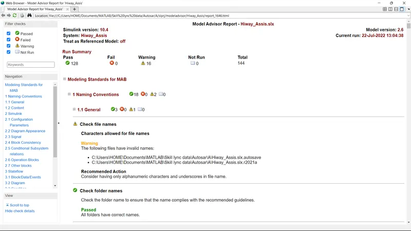
*Model advisory check according to the MAAB Guidelines
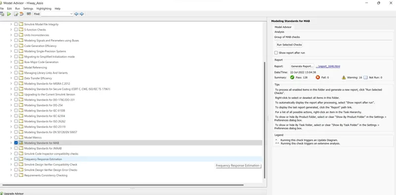
*The model advisory report