Project 2 - Development of TFT Cluster Speedometer Software Component
Project 2 - Development of TFT Cluster Speedometer Software Component
Aim:
Develop the Simulink model based on the given requirements and Perform the complete V and following V workflow for the obtained model
- Simulink model file
- SLDD file
- Requirement tagging report
- Fixed-point Tool
- Model advisor - JMAAB compliance report
- SLDV Design error detection report
- Functional test case, MIL, SIL harness, coverage Reports
- SLDV test generation report
- Auto-code generation report, .c & .h codes
- Poly space analysis report / outputs
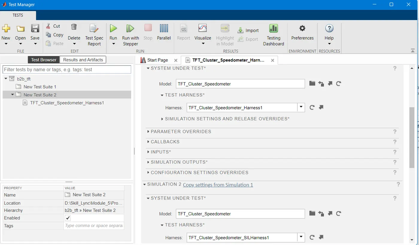
- Test manager reports – baseline & back-to-back testing
Description:
Cluster Instrument receives the signals from other ECU via CAN bus interface. It also receives commands from the driver via steering wheel buttons. The signals are then processed by the Cluster ECU, after which the Cluster ECU may send the vehicle information to the LCD or light the LEDs and so forth, according to the results. Therefore, the Cluster ECU can be viewed as a carrier of the information flow.
1. Simulink Model
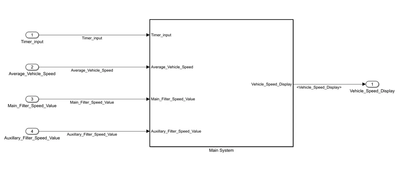
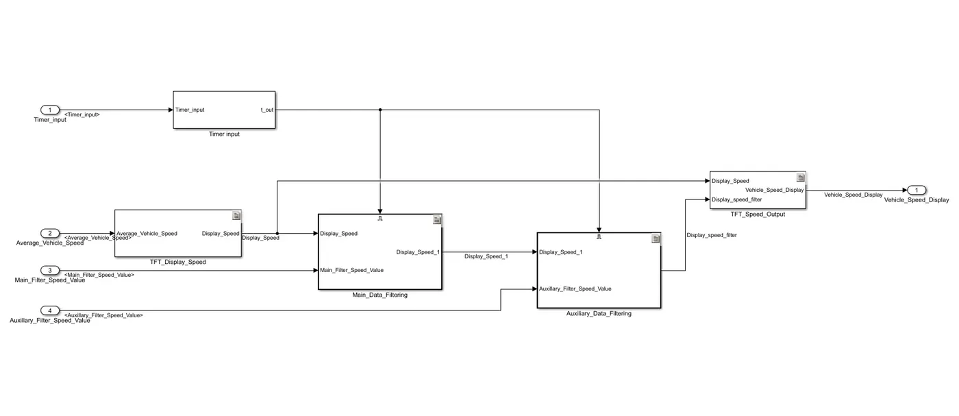
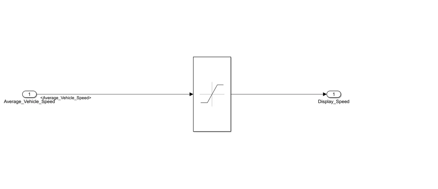
Model Subsystem/ TFT_Display_Speed
Model Subsystem/ Main_Data_Filtering
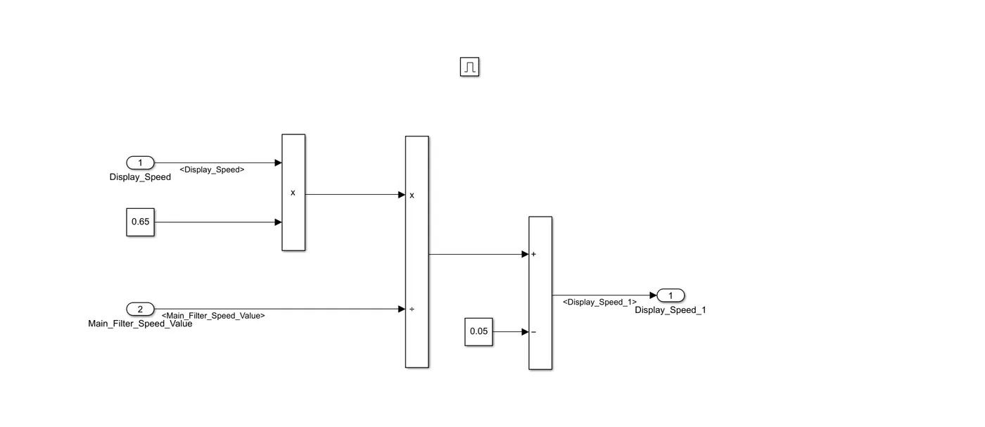
Model Subsystem/ Auxiliary_Data_Filtering
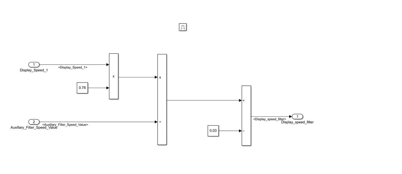
Model Subsystem/ TFT_Speed_Output
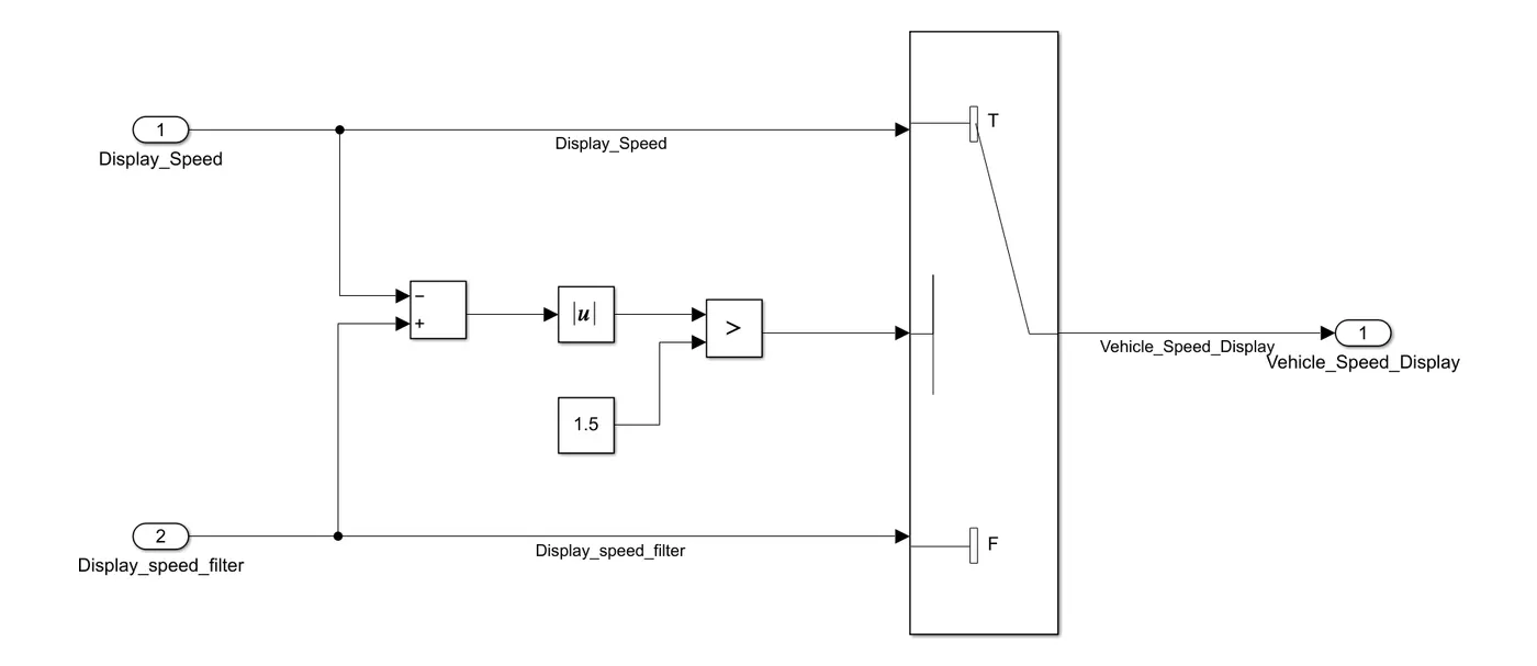
2. SLDD
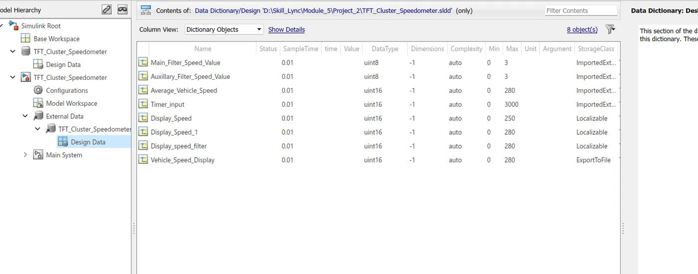
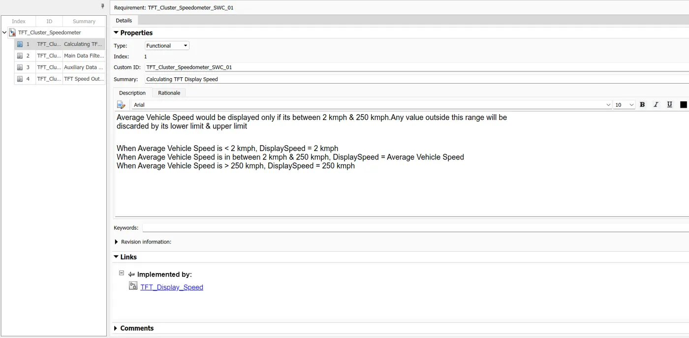
3. Requirement tagging
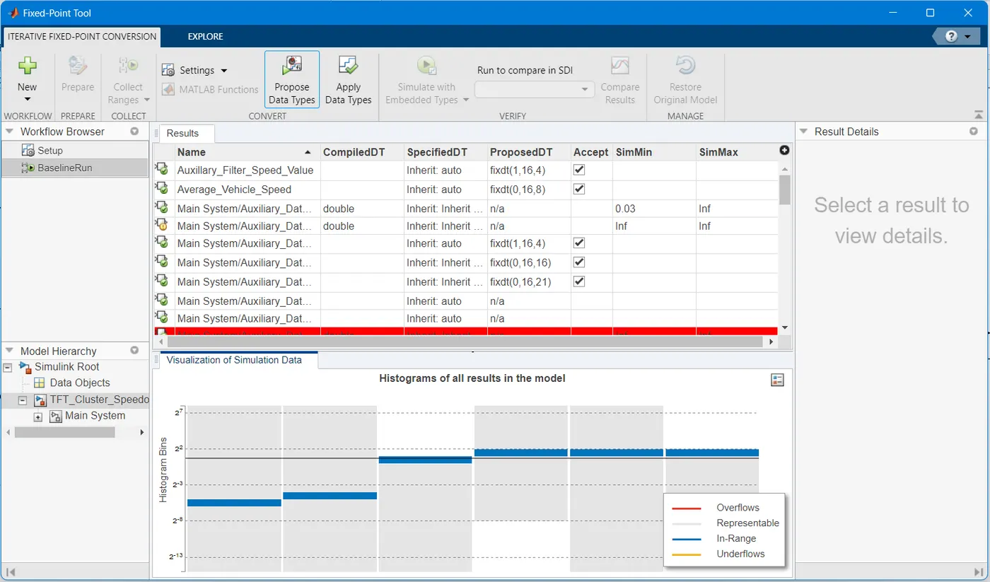
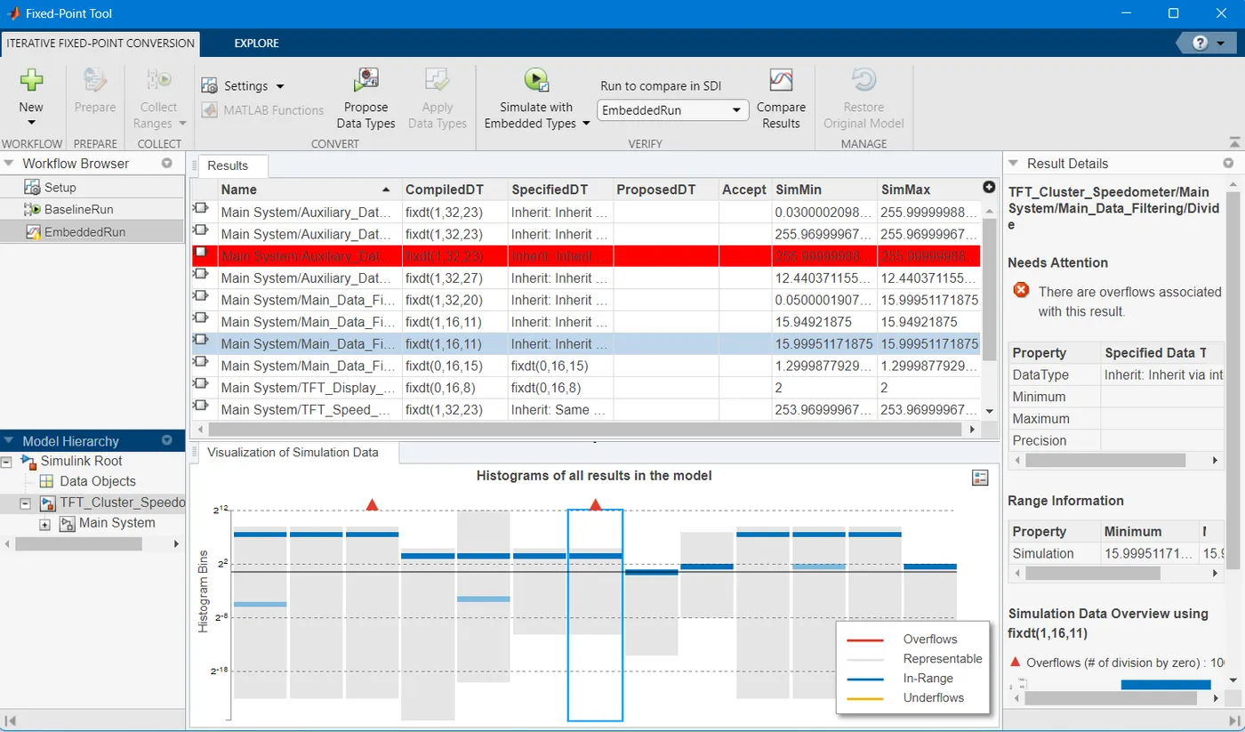
4. Fixed-point Tool
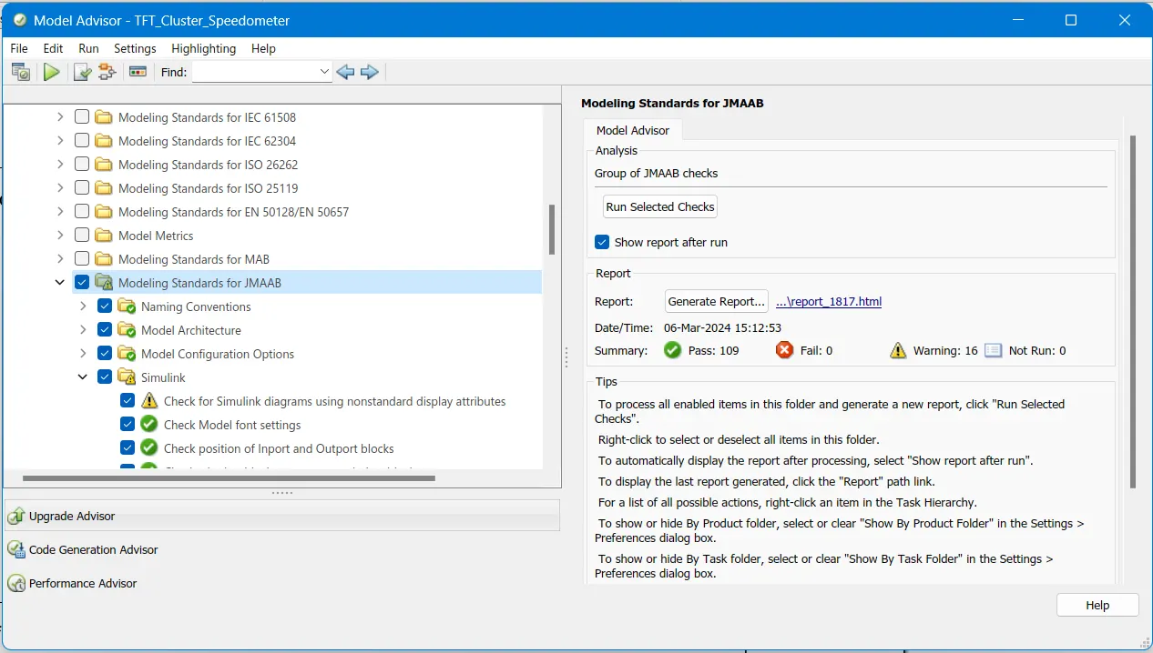
5. Model advisor - JMAAB compliance Report
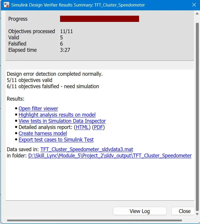
6. SLDV Design error detection report
7. Functional test case
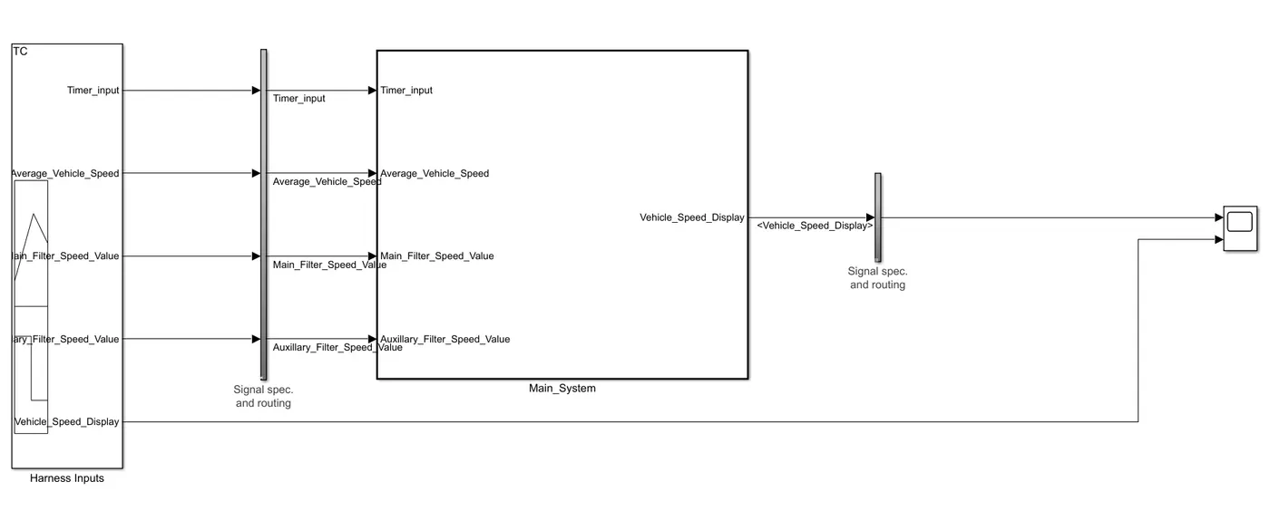
8. MIL Harness
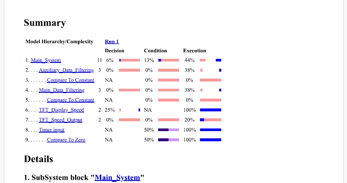
8.1 MIL- MCDC Coverage Reports
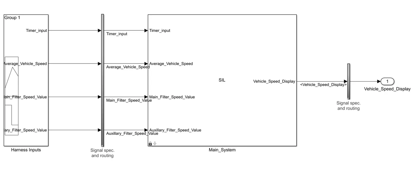
9. SIL Harness
9.1 SIL- MCDC Coverage Reports
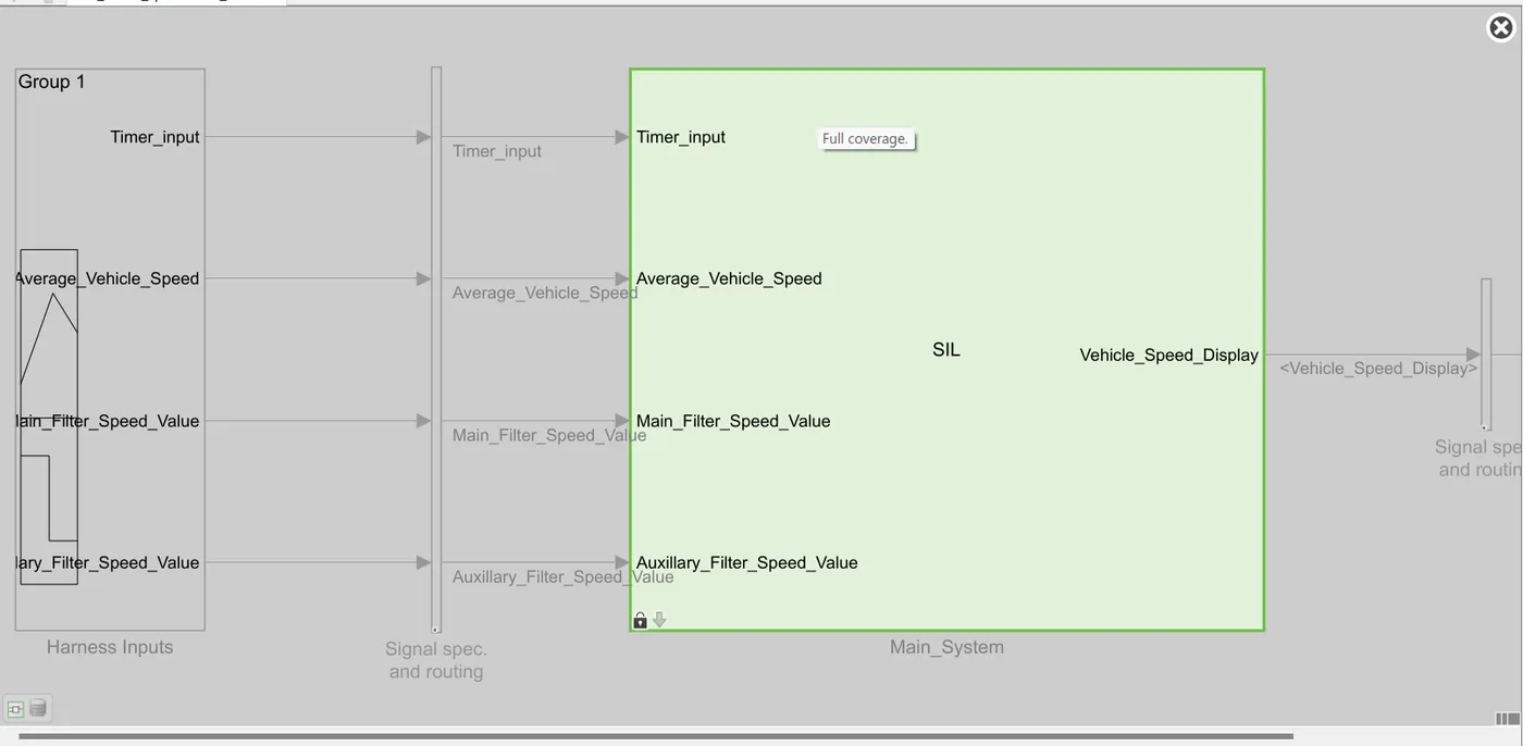
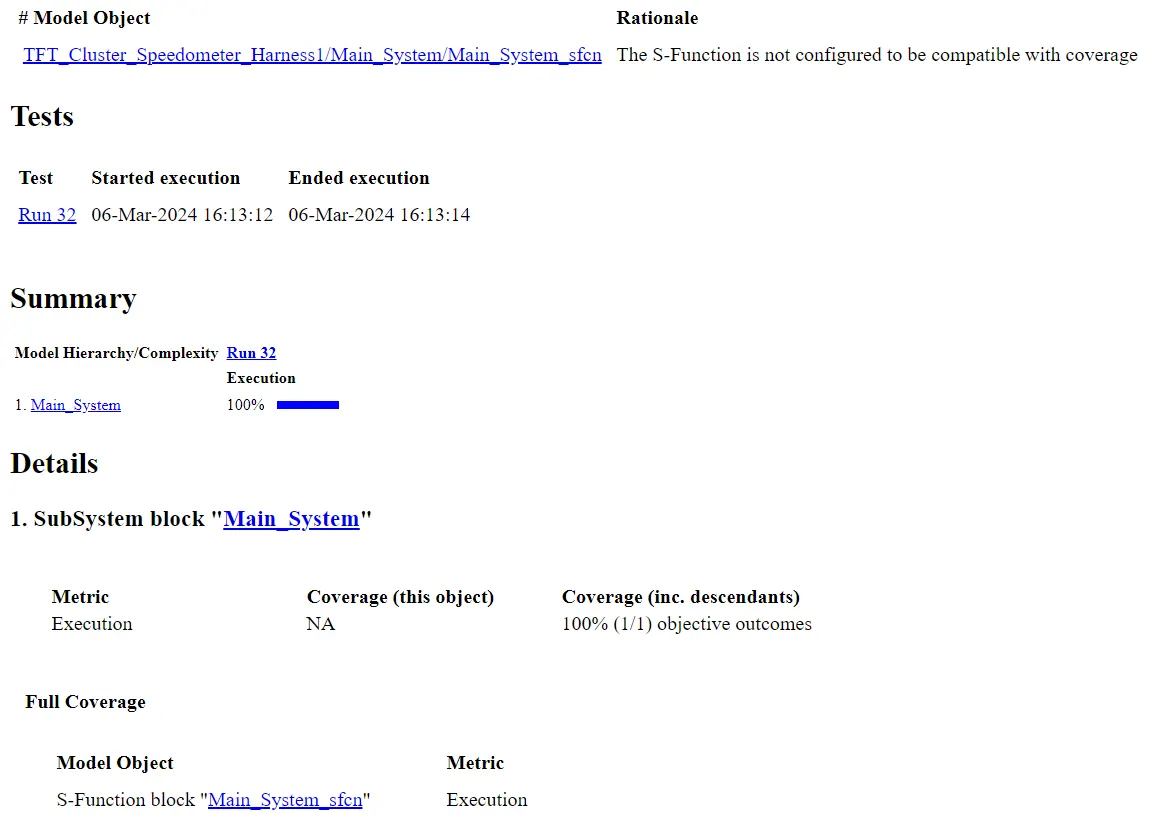
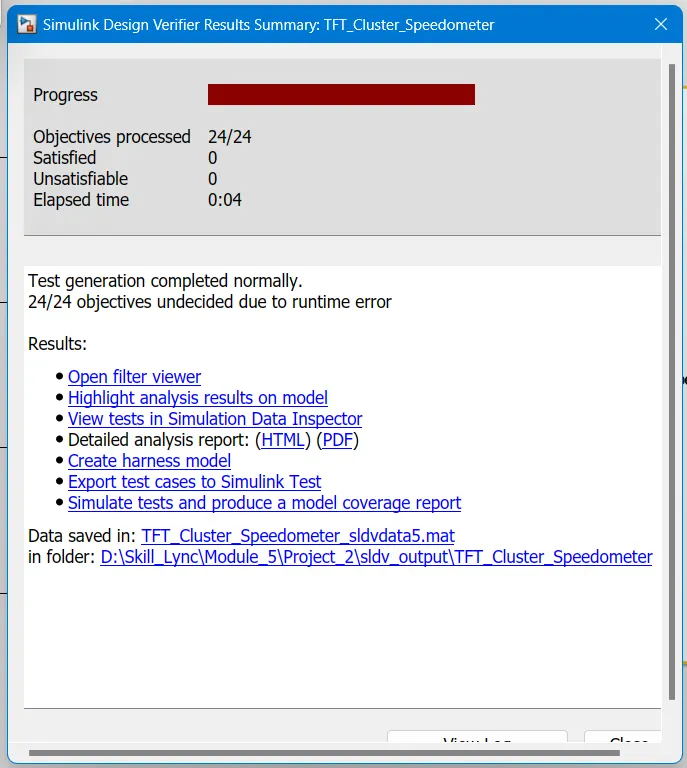
10. SLDV test generation report
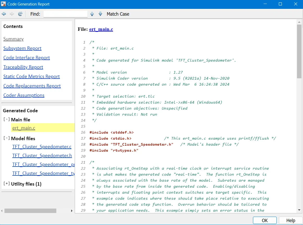
11. Auto-code generation report, .c & .h codes
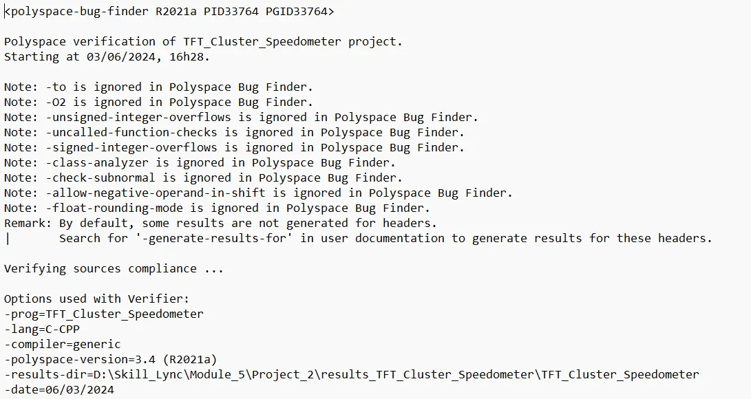
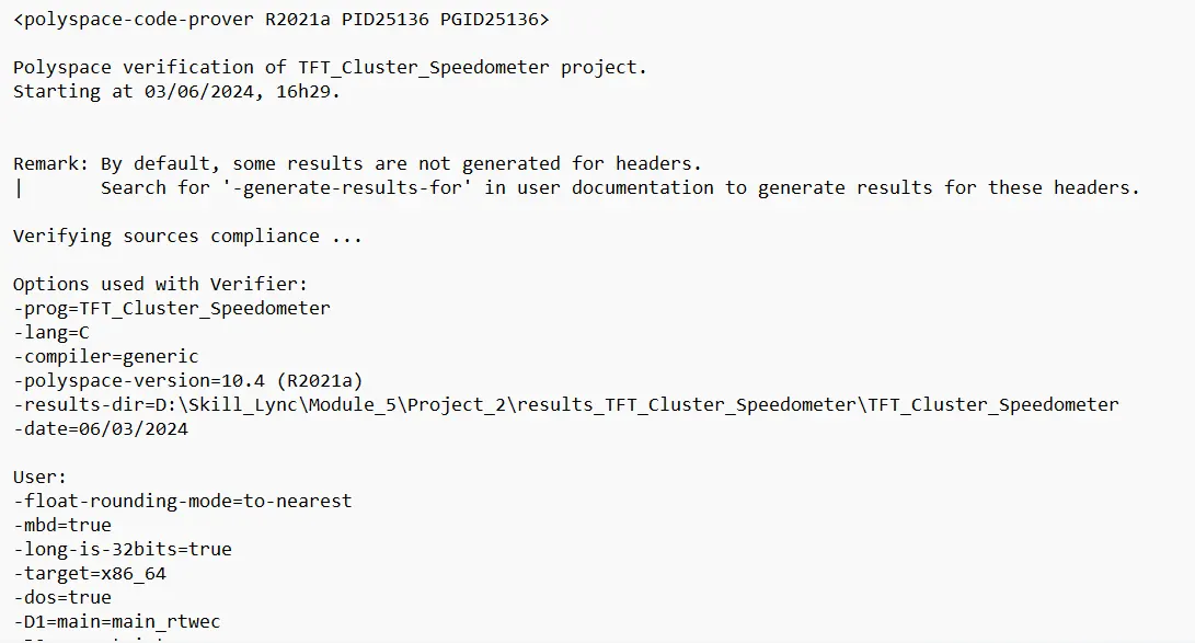
12. Poly space analysis report / outputs
Bug Finder Log
Code Prover Log
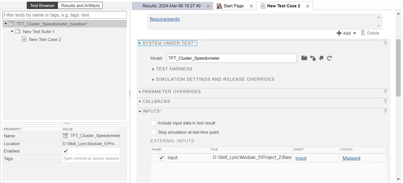
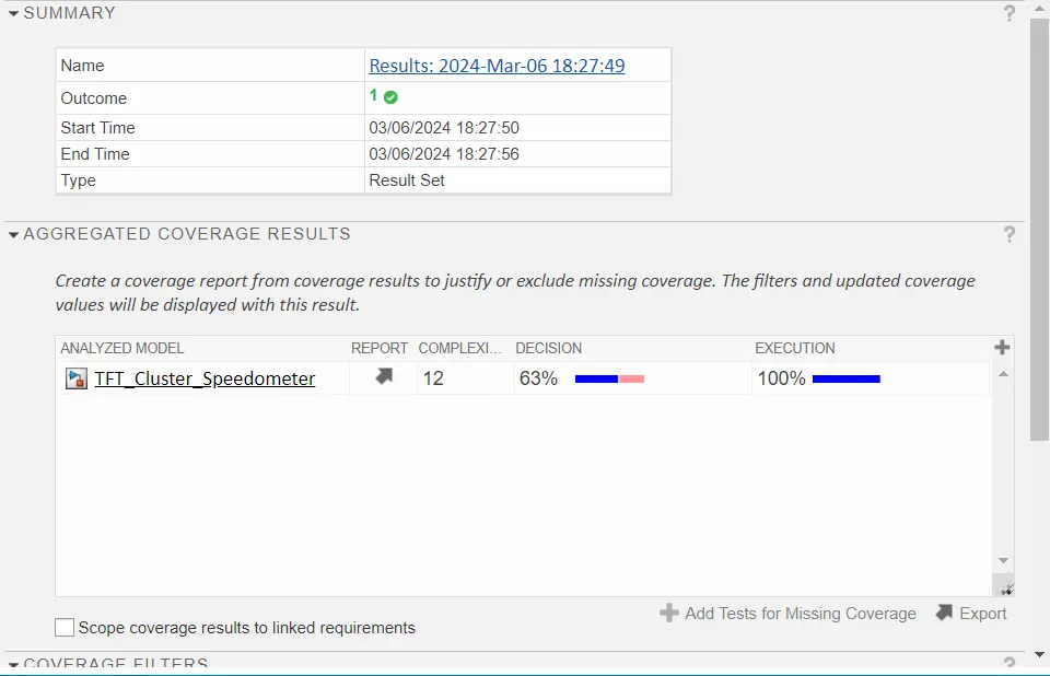
13. Test manager reports – Baseline testing
14. Test manager reports – Back-to-Back testing