Project 2_Design & Analysis of a Hostel building at Guwahati, Assam
AIM:
To create and Anaylse the given builidng in ETABS 2020, the strcutural model has to be prepared in accordance with IS1893 and as per IS 13920. To design the pile cap and pile reinforcement details. Tie beam connecting the pile caps, so sketch the column reinforcemet, to produce the framing paln and beam detailing for ground floor.
GIVEN DATA:
Loction: Guwahati, Assam
Function: Hostel block in an academic institute
- The walls will be made of AAC (Autoclaved aerated concrete) blocks.
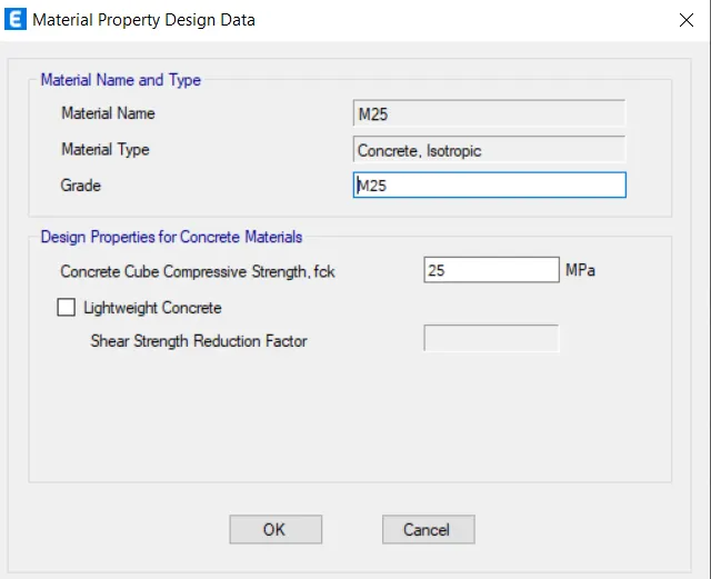
- M25 Grade of concrete
- Fe500 longitudinal reinforcement
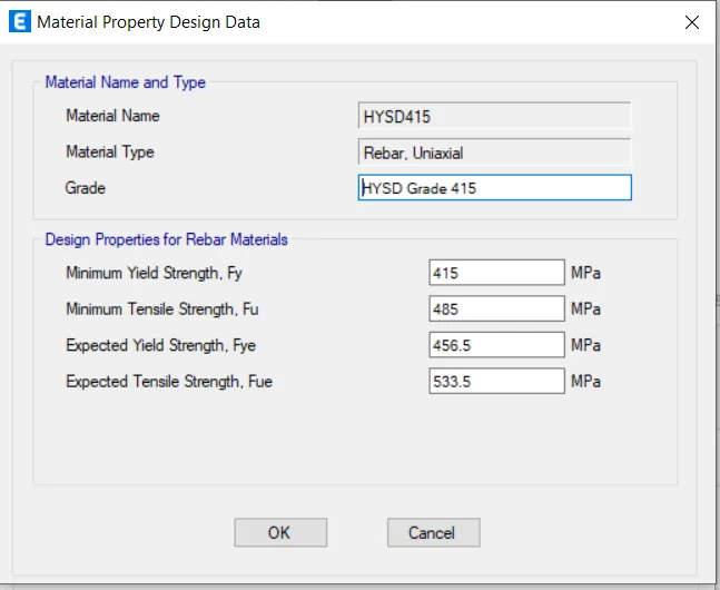
- Fe415 Shear reinforcement
- Soil type is 3
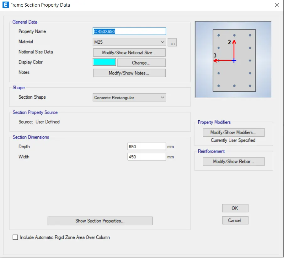
- Column Sizes is 450 X 650MM
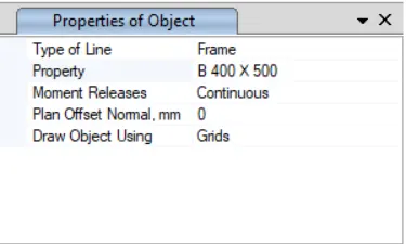
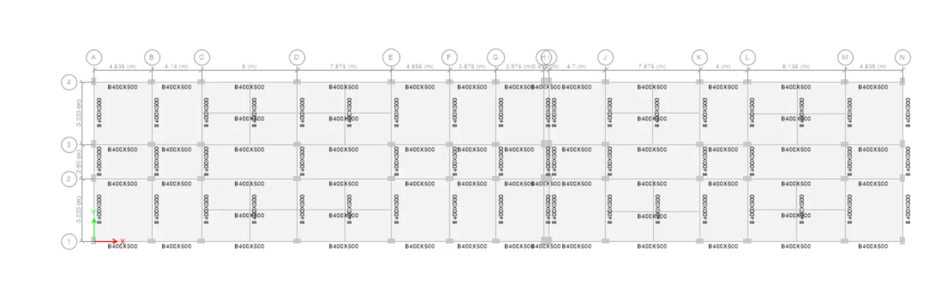
- Beam Sizes is 400 X 500MM
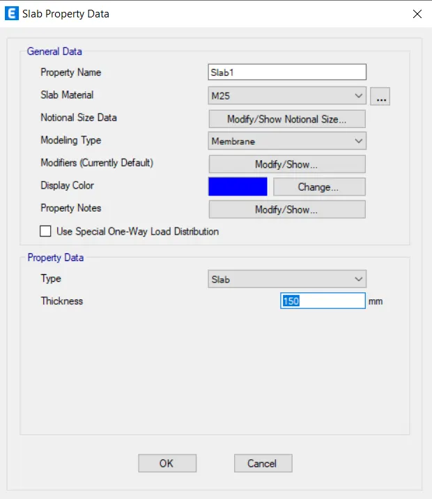
- Slab is 150mm thickness
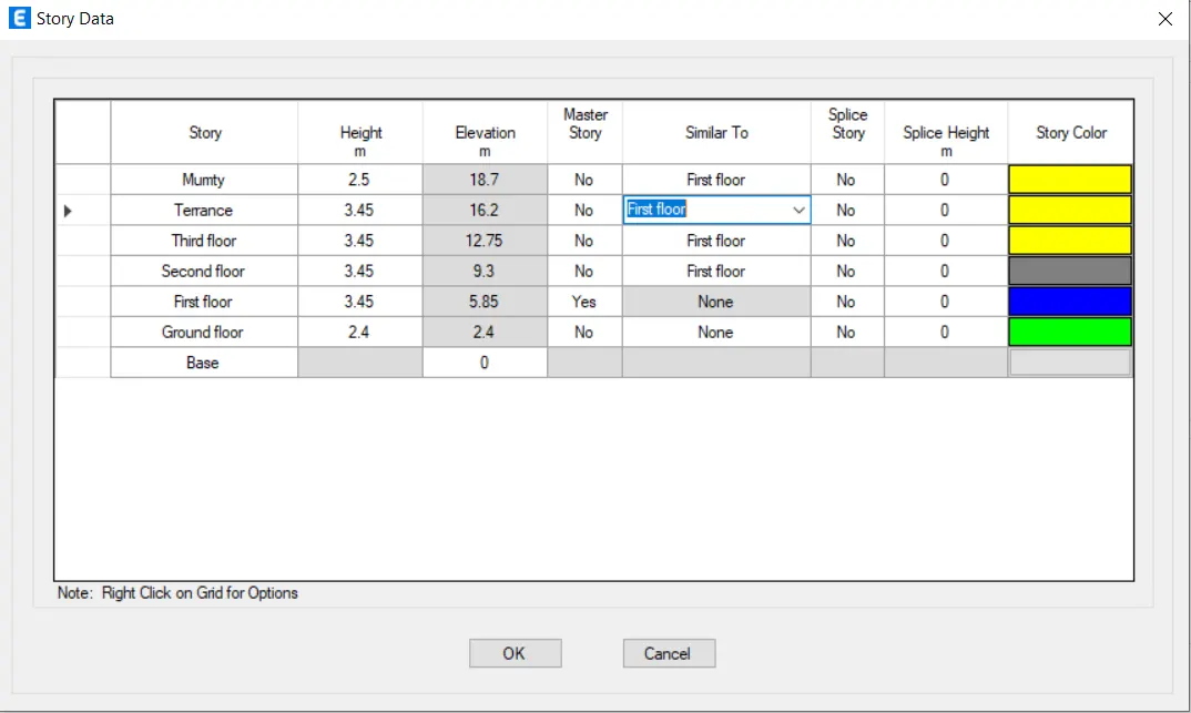
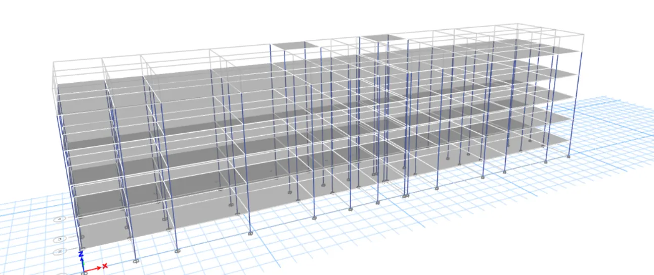
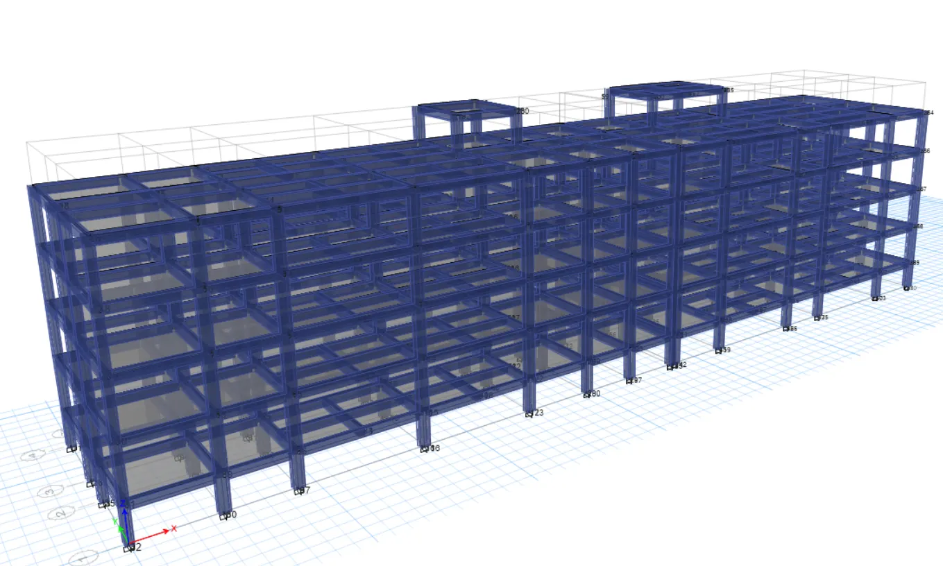
- Pinned support, Base +5 story (Plinth to Roof)+1 Mumty
- Guwahati seismic Zone is V
The following design IS codes
1. IS 875 part-1,
2.IS 875 Part-2,
3.IS 13920,
4.IS 1893,
5.IS2911 part -2,
6.IS 456,
7.IS 34
INTRODUCTION:
1. ETABS is the software which is being used to created a structural model of given building,
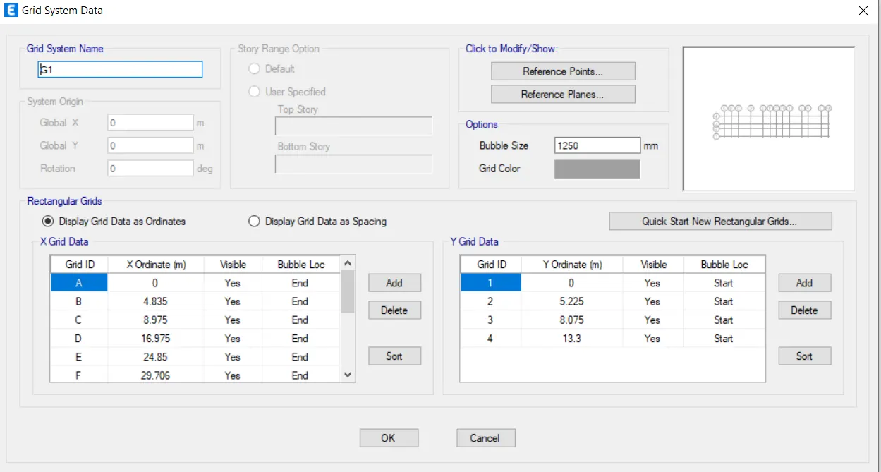
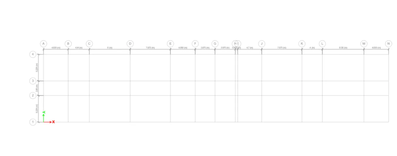
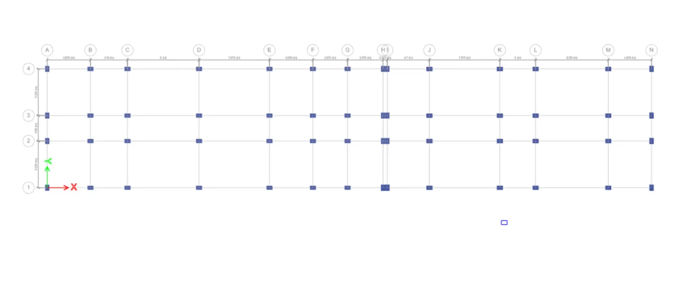
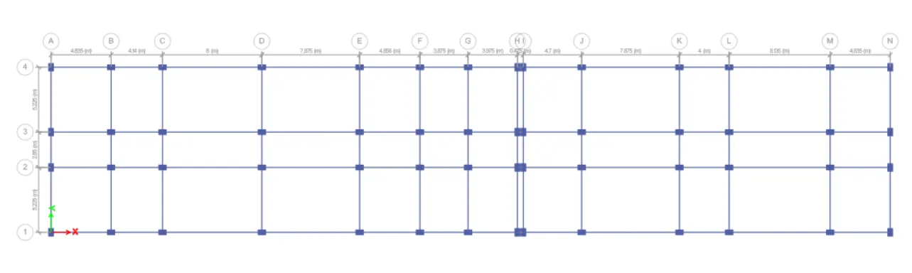
2. In the first step note down the value of grid spcaing from the given strctural plans,
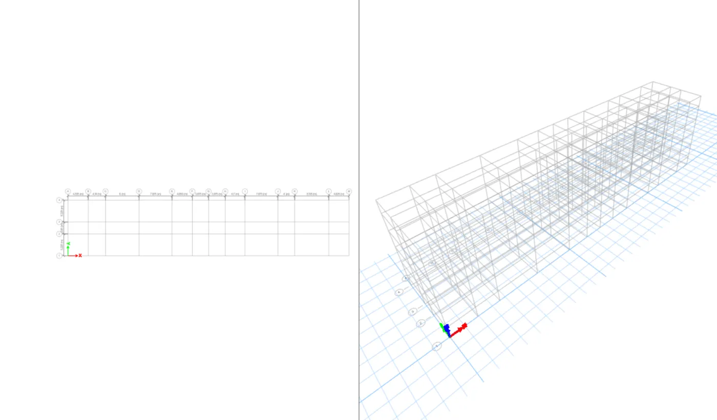
3. Next created the structural model and run the model,
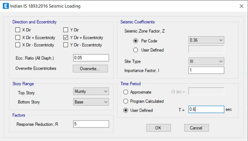
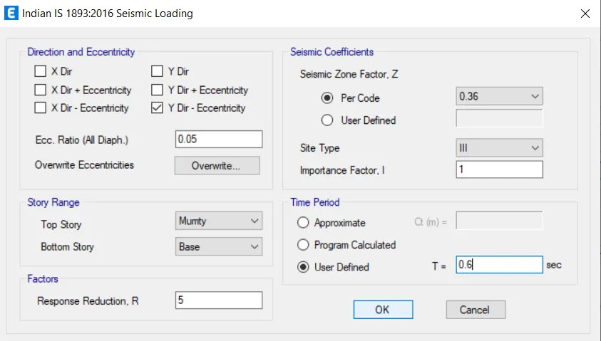
4. Analyse the results and note down the results value from ETABS,
5. Next the to export the model to SAFE 2020 software in oreder to design the foundations.
PROCEDURE:
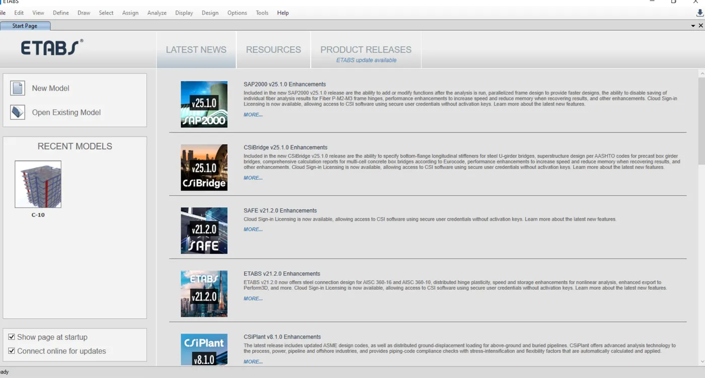
1.In the first step open the ETABS software go to file and click on new model
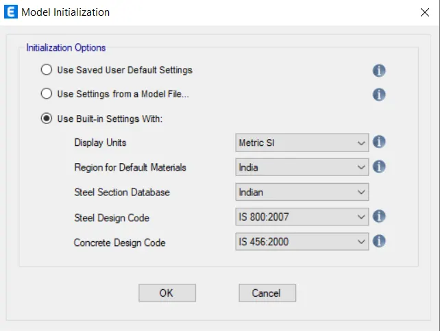
2.Model initalisation window will be appeared
3.Click on the use built in setting and select the india codes and click ok
4.Click on the custom grid data and click ok
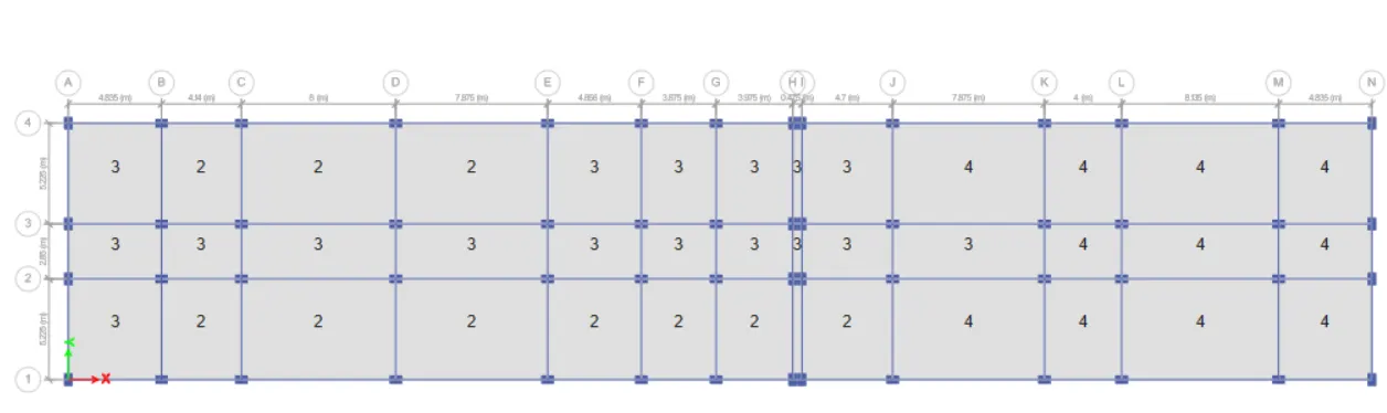
5. Now the values as per the given plans are inserted and our model will be ready
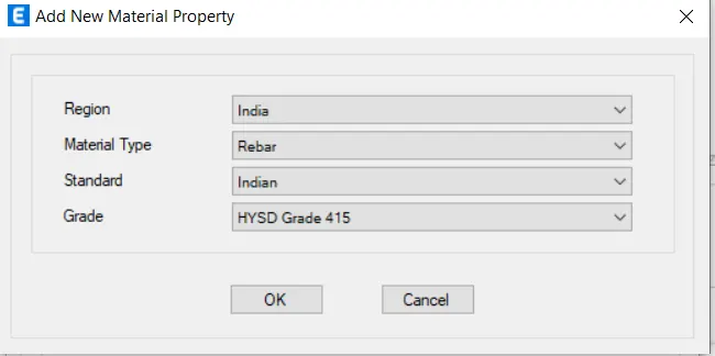
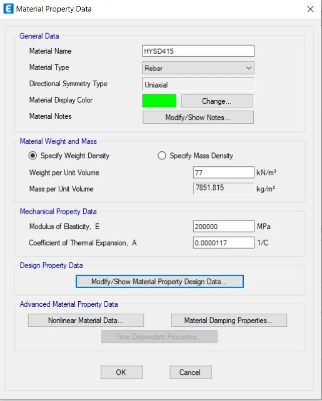
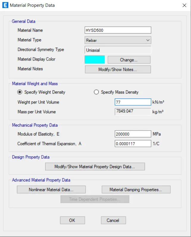
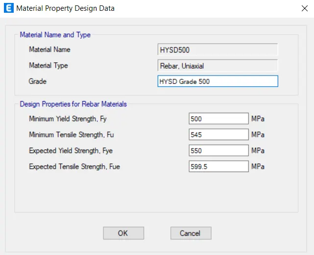
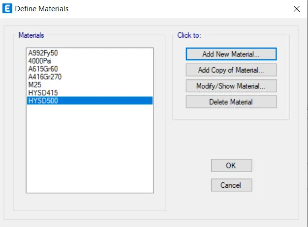
6.In the next setp material has to be defined Go to defined and click on material properties and add the concrete and rebar material specification.
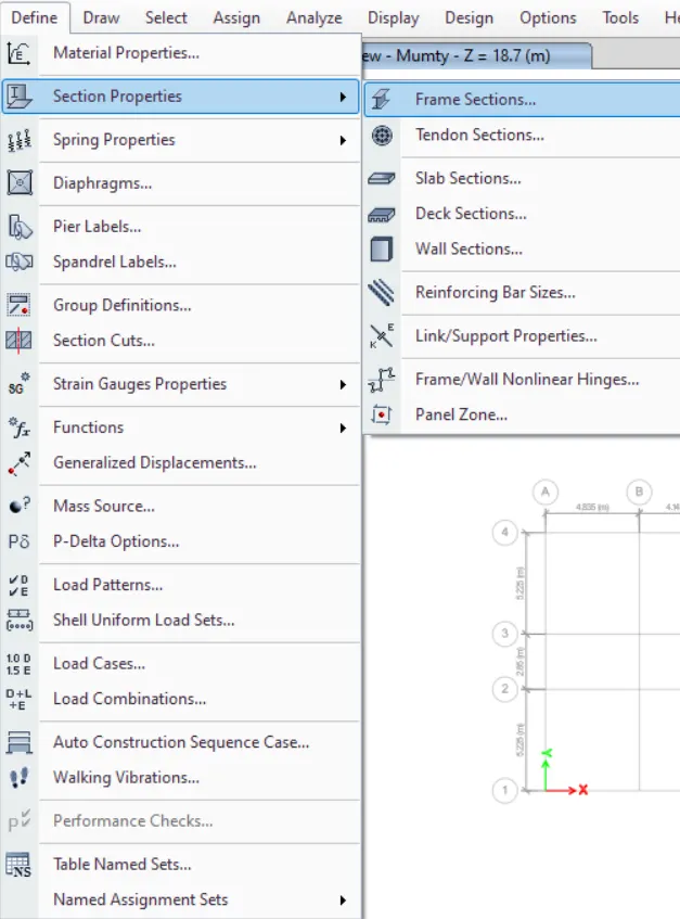
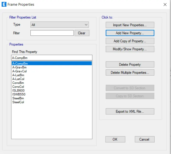
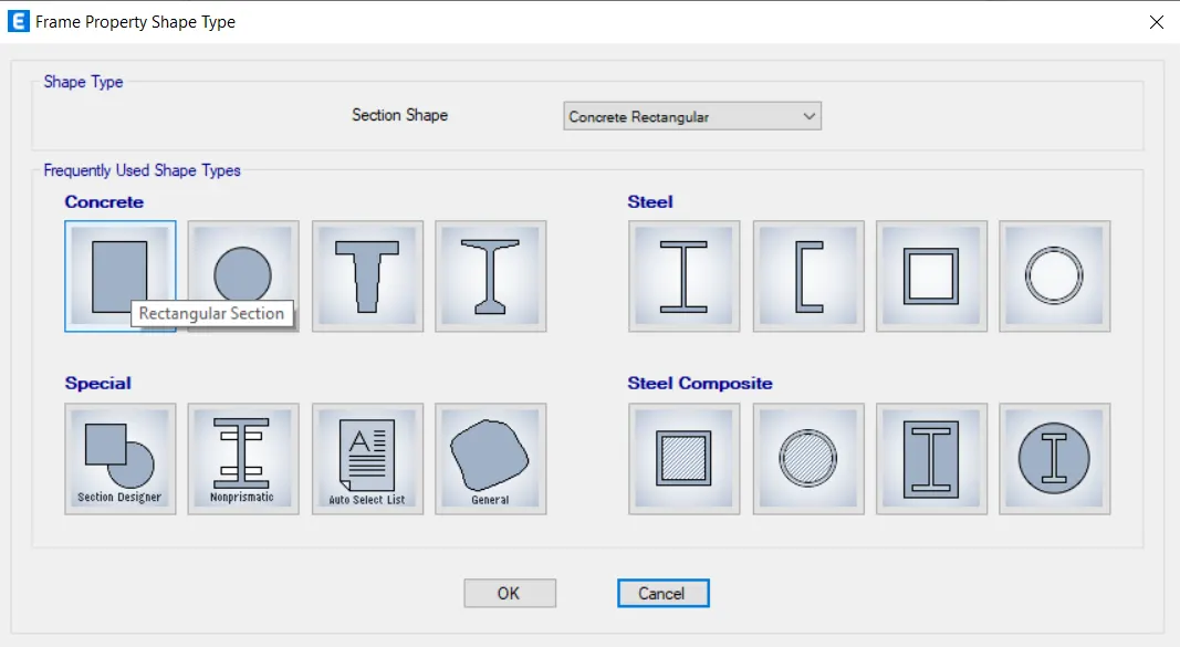
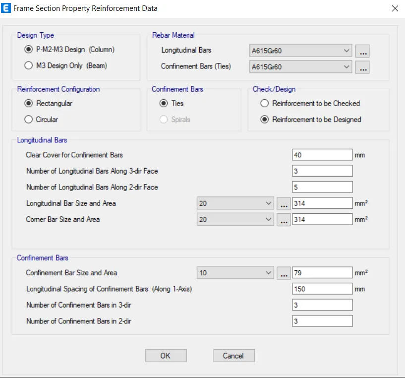
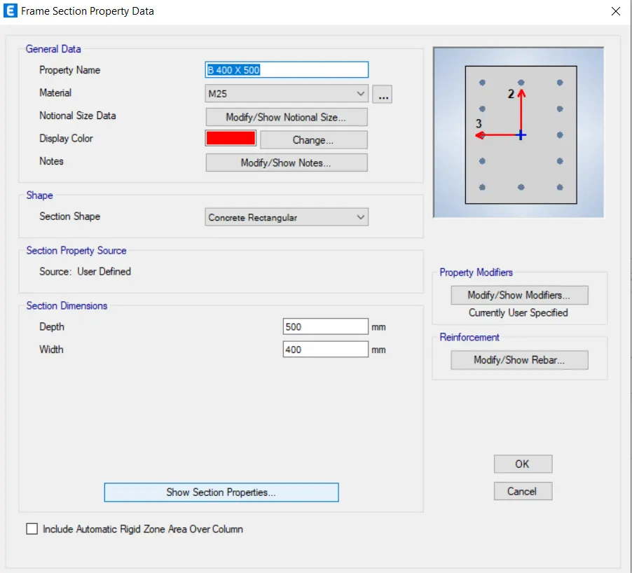
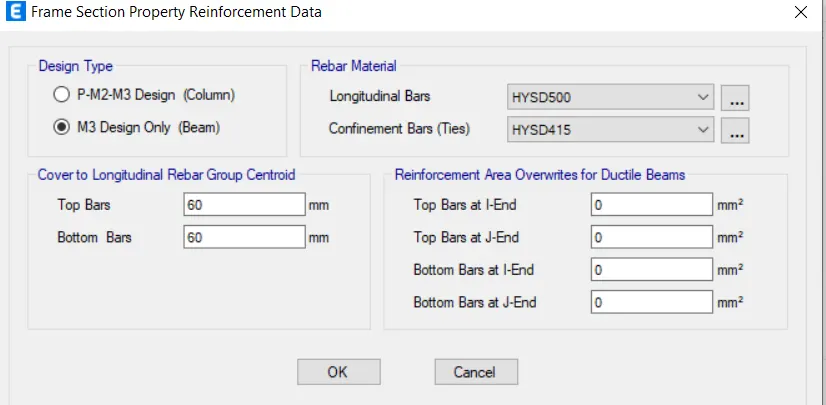
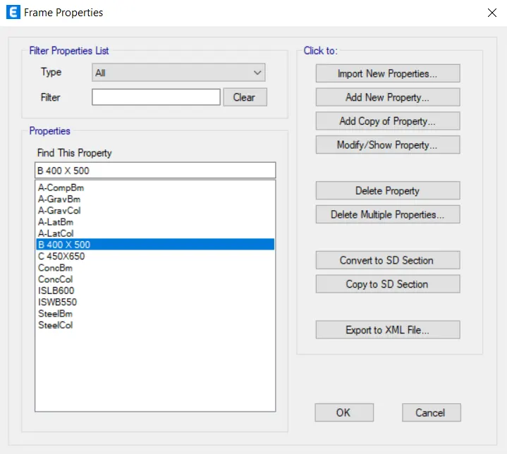
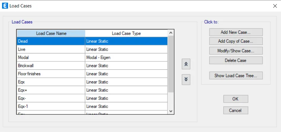
7.In the next step section properties has to be define Go to and click on section properties and add the beam and column specificaion
8.450X605mm Column size is provided for the all the column
9. 450X500mm Beam size is provided for the beam at periphery so as increase the torsional resistance of the building
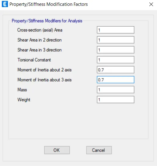
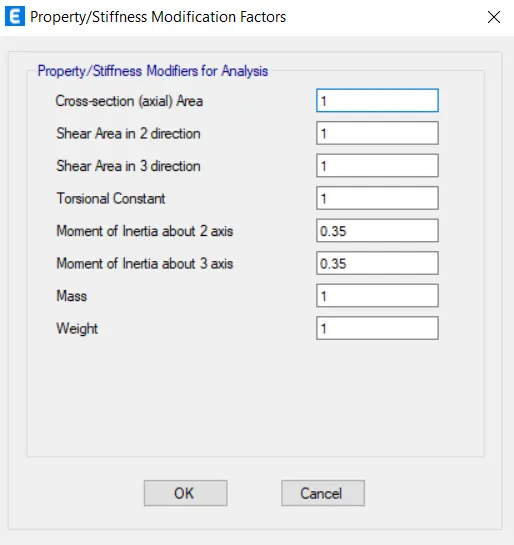
10.Moment of inertia for beams and columns should be reduced by 0.35% and 0.7% respectively
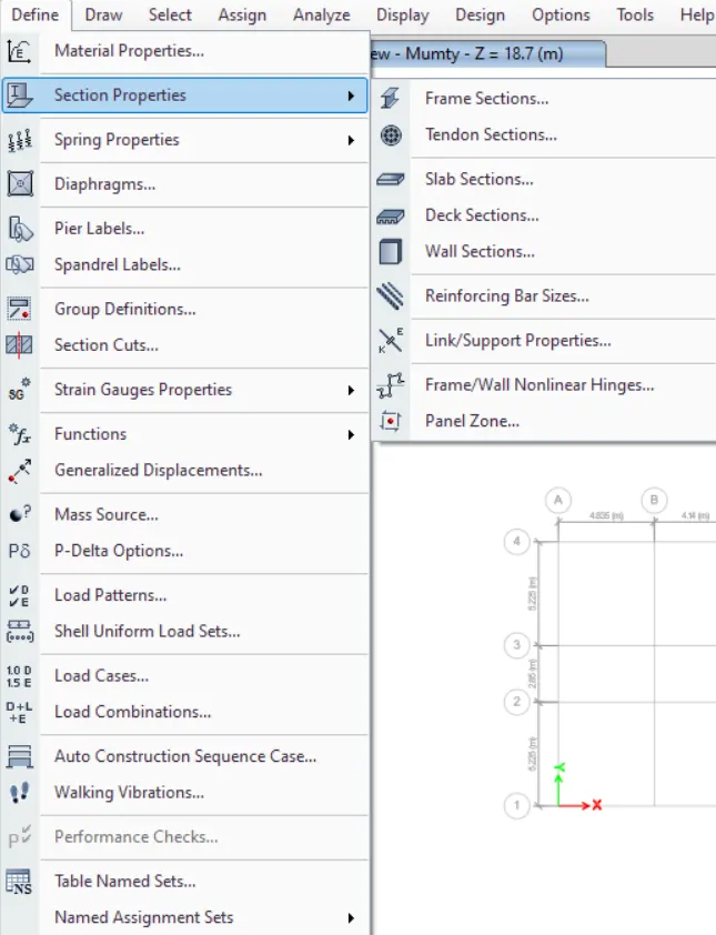
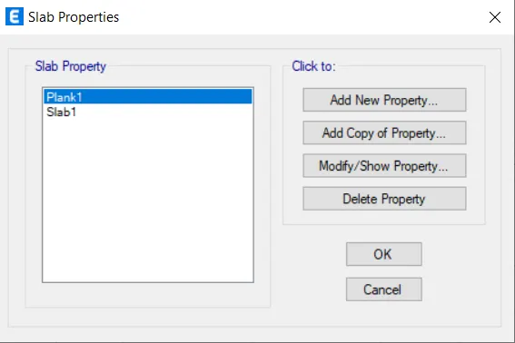
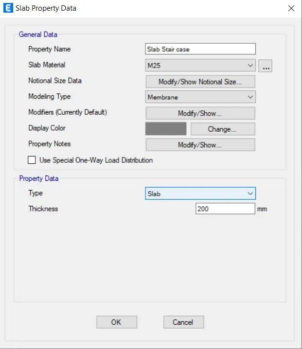
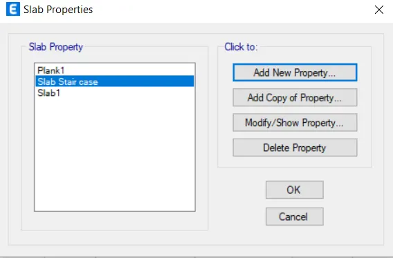
11. In the next step define the slab properties by going in to define and slab sections. Add the slab property as while defining the slab for stair case it should be one way
12. Define the stair case slab slab provide its thickness as 175mm (varies from175-225mm)
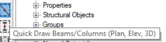
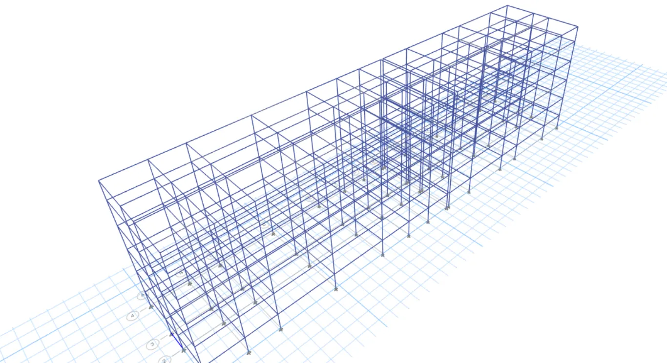
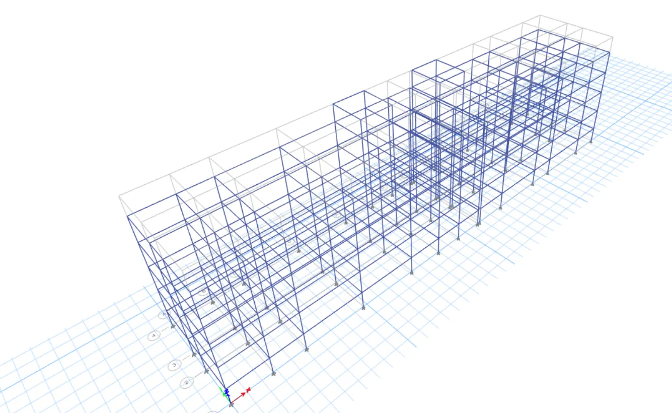
13. Draw all the beam using beam command
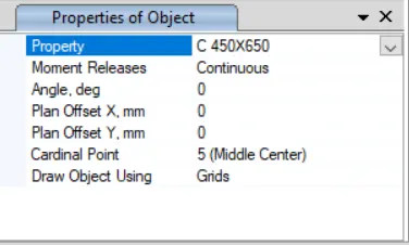
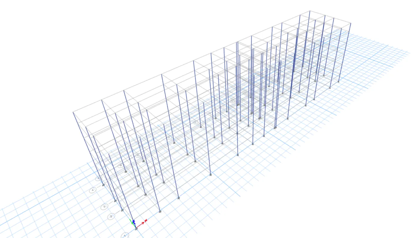
14.Draw all the columns using column command
15. In the next step slabs are drawn using slabs command
16. Now we have to decide the locaction of shear wall and how much should be the length of the shear wall
17. As per india standards the length of the wall should be 5-2% in each direction
18.The thickness of shear wall is assumed to be 250mm
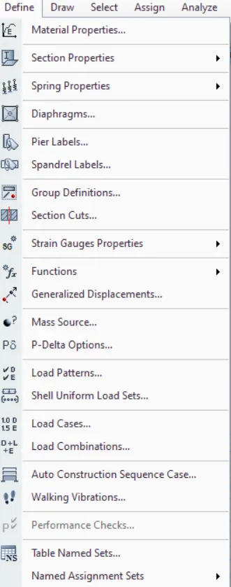
19.Now go to define and define the loads
20.Next select the beam and floor and add the loads
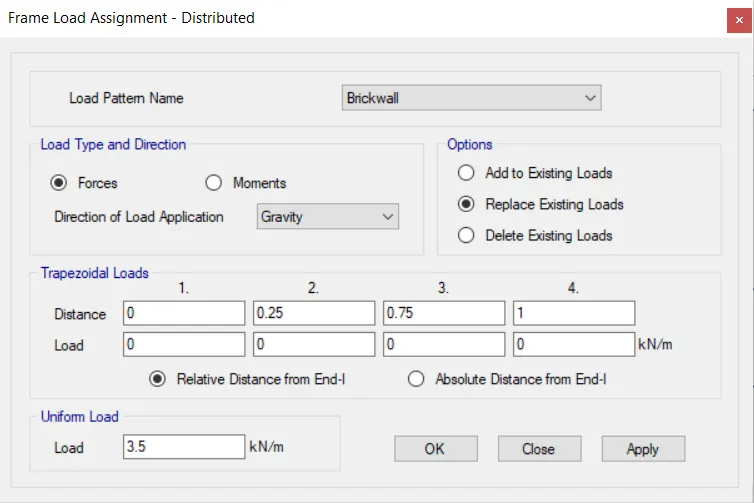
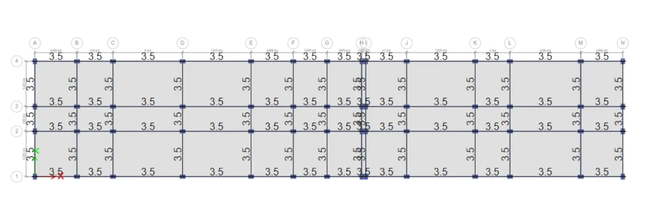
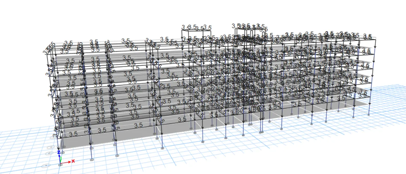
21. AAC block of 3.5KN/M since the AAC block are used
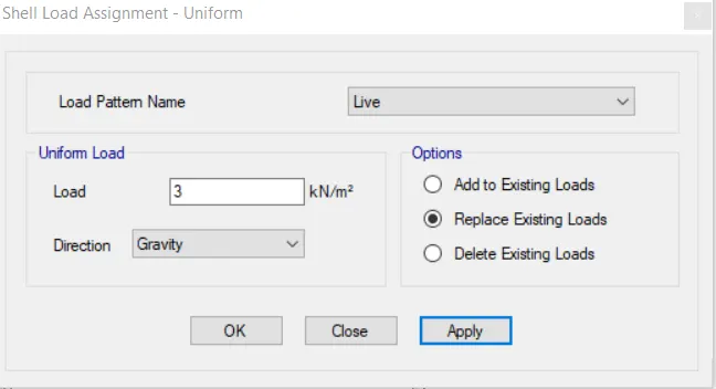
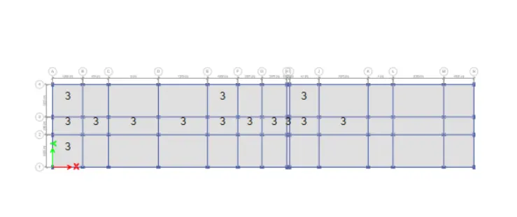
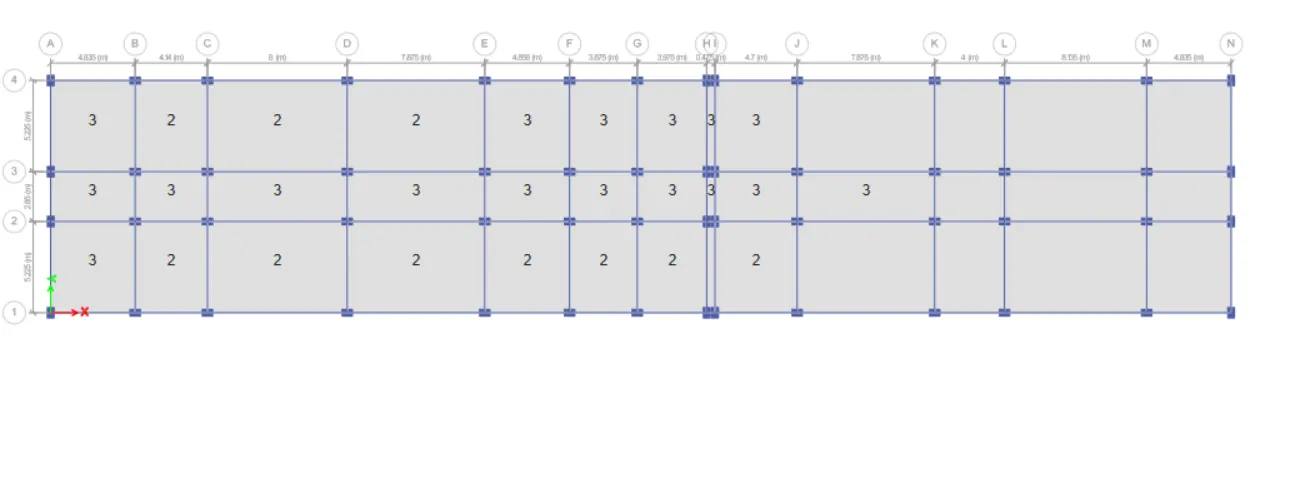
22.The live load values are got from IS 1875 part 2 for residential buildings
23. As per table 1 of IS 875 Part 2
24. For Hostel buildings
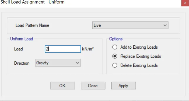
Livinf Room, Bed rooms and Dormitories 2KN/M^2
Kitchen and Laundries 3KN/M^2
Billards and Public lounges 3KN/M^2
Store Room 5KN/M^2
Dinning rooms Cafeterias and Resturant 4KN/M^2
Office rooms 2.5KN/M^2
Bath and toilets 2KN/M^2
Corridors, passages, stair case 3KN/M^2
Balconies 4KN/M^2
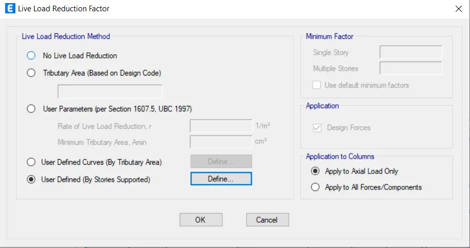
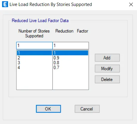
25. As per clause number IS 875 part 2 reduction factor should be applied on the imposed loads
26. Live load at the roof floor needs to be reduced hence 2KN/M^2 is applied
27. Floor finish on all the floors 2KN/M^2
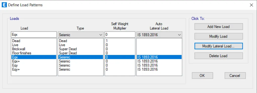
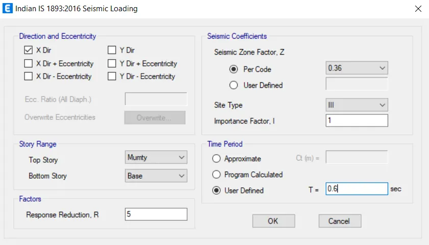
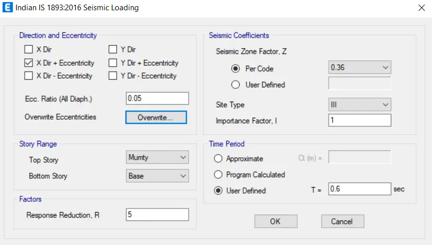
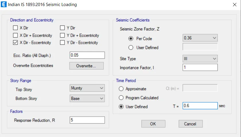
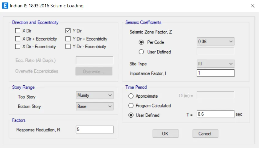
28. Seismic loads should be define soas per IS 1893 Table No 8 importance factoe should be
29. Since the building
30. Time period is calculated as per clause number 7.6.2 of IS 1893
T=0.09hsqrtd
Tx=(0.09*16.85)/(67.7)^0.5=0.184second .or Ty=0.09*16.85/(13.3)^0.5 = 0.415Sec
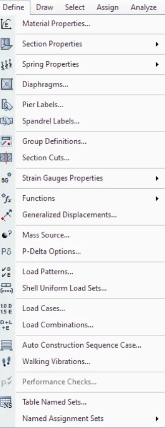
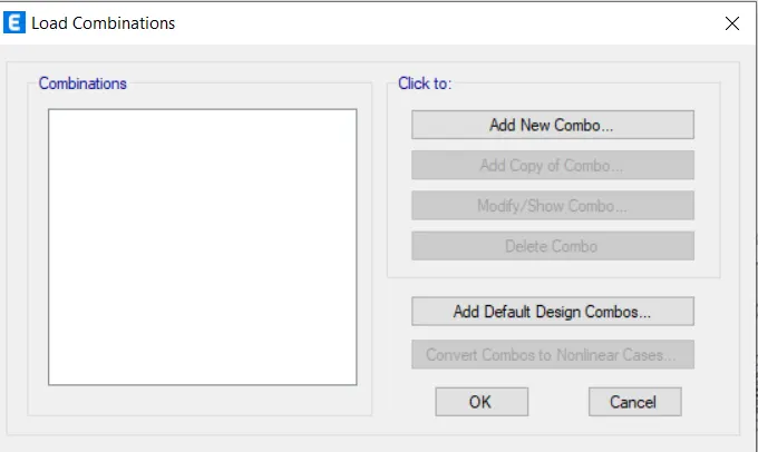
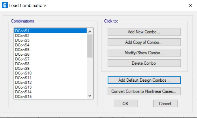
31. Now define the load combinations
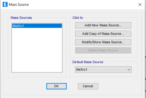
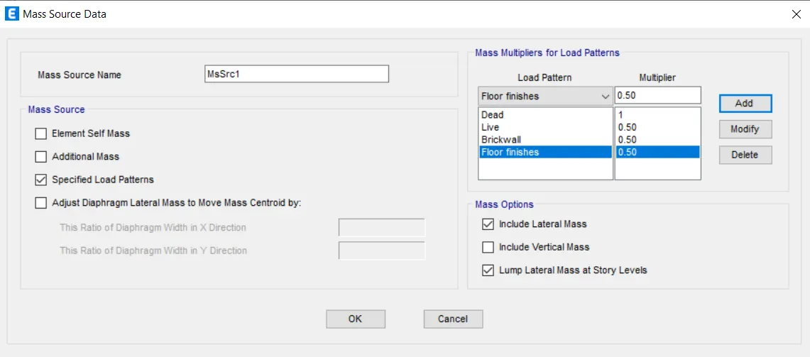
32.In the next step we have to define the mass source, for that go to define and click on mass sourece and add on the new, click on specified load data, in the amss options click on include lateral mass and lump lateral mass at story levels the load patterns add lump lateral mass at story levels, in the load pattern add Multipier 0.25 for LL and 1 for all the dead and super dead loads
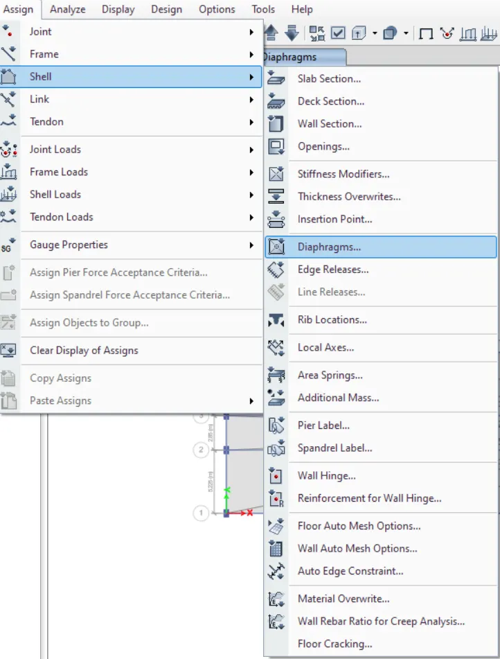
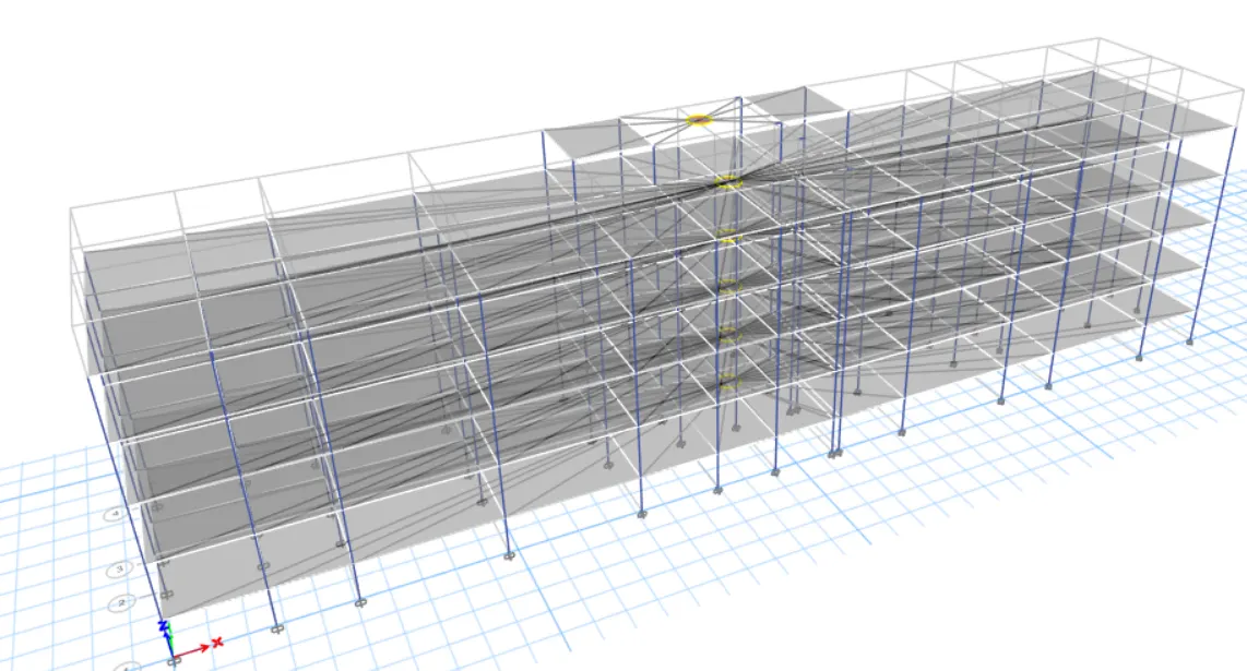
33. And select all the floors and apply diaphragn D1
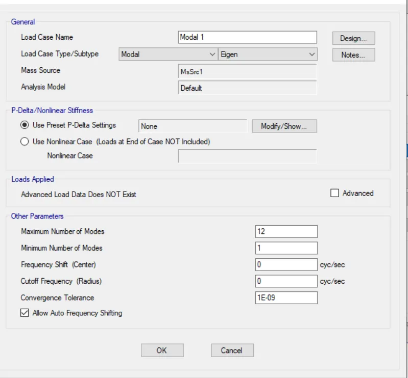
34.In the next step we have to define for the modal cases for that go to define and click on modal cases click add new modal cases select and put the number of modes shape required
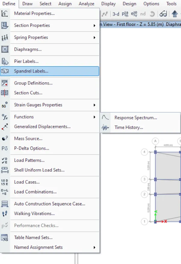
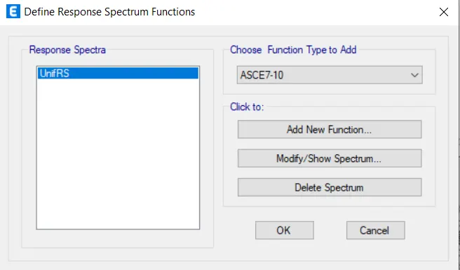
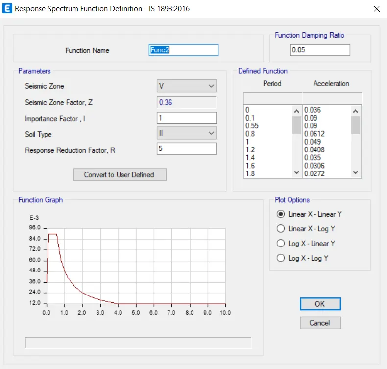
35. Now go to define function and click on responese spectrum add new function in accordance with IS 1893-2016 check all the value click ok
36.Name the function as IS function, response spectrun IS function IS 1893-2016 tab will appear check all the value Seismic zome facctor soil type, importance factor click on linear X liner Y click ok
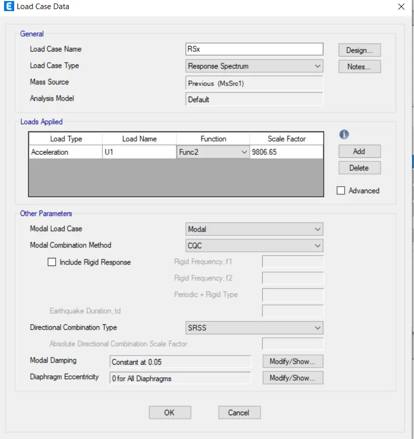
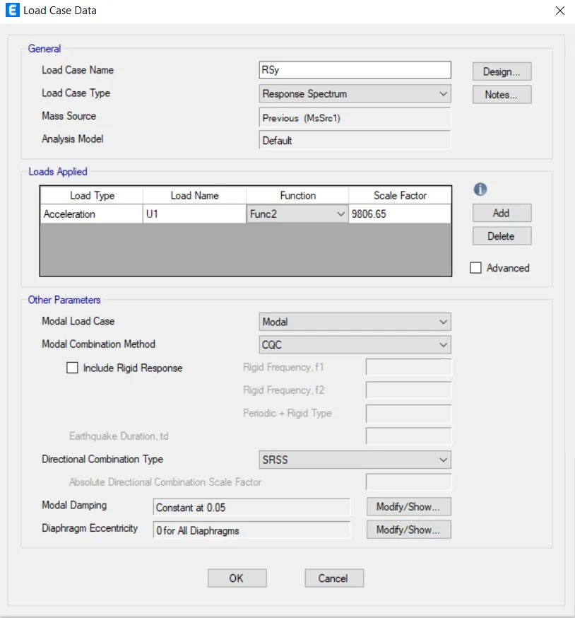
37. Now go to define load cases and click on add new case and Add RSX andRSY
38. Select the response spectrum click and Add Select the function as IS Function and U1 for RX, And U2 for RSY and IS function
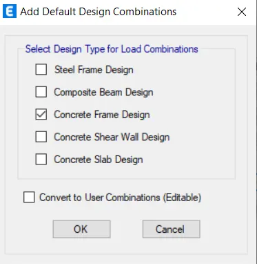
39. Go to define click on load combinations add click on default design combo, click on created frame design and click on convert to design combo click ok
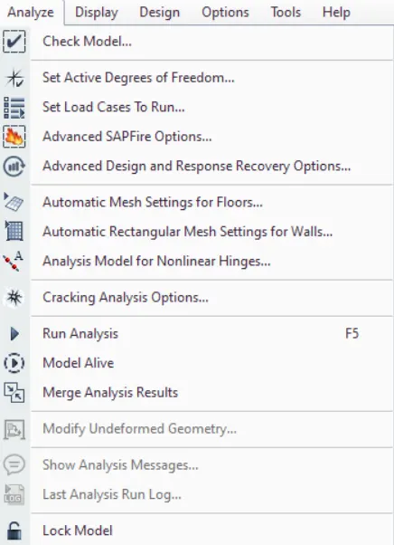
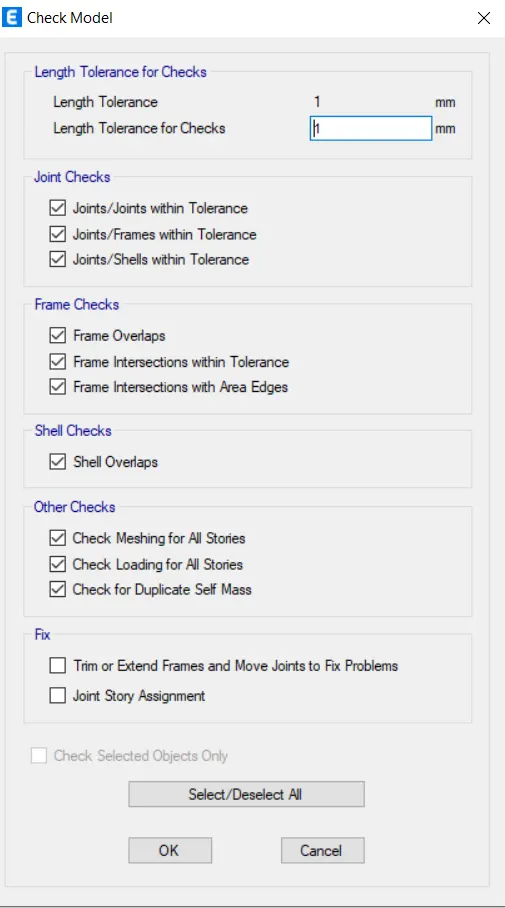
40. Now check the model if there are any warning correct it abd run model
Results
1. Go to display the click show tables and then structural data click ok
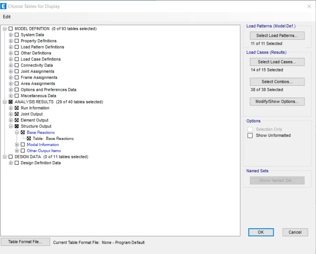
2. Click on show tables select the analysus result structure output click ok
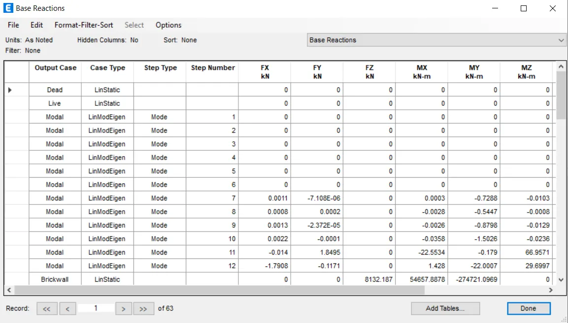
3. Select the base reaction and check the eqx, eqy and value Rx and Ry value see which values are larges if the Ex,Ry value are lessser than the Eqx, Eqy unlock the model and then go to define load case and delete the Rx, Ry cases and again select the load combinations and define load case again
4. Go to modal mass participation ration and check the values for U1,U2,U3 value sume of these UX,Uy,UZ for the first modes it should be greater than 65%
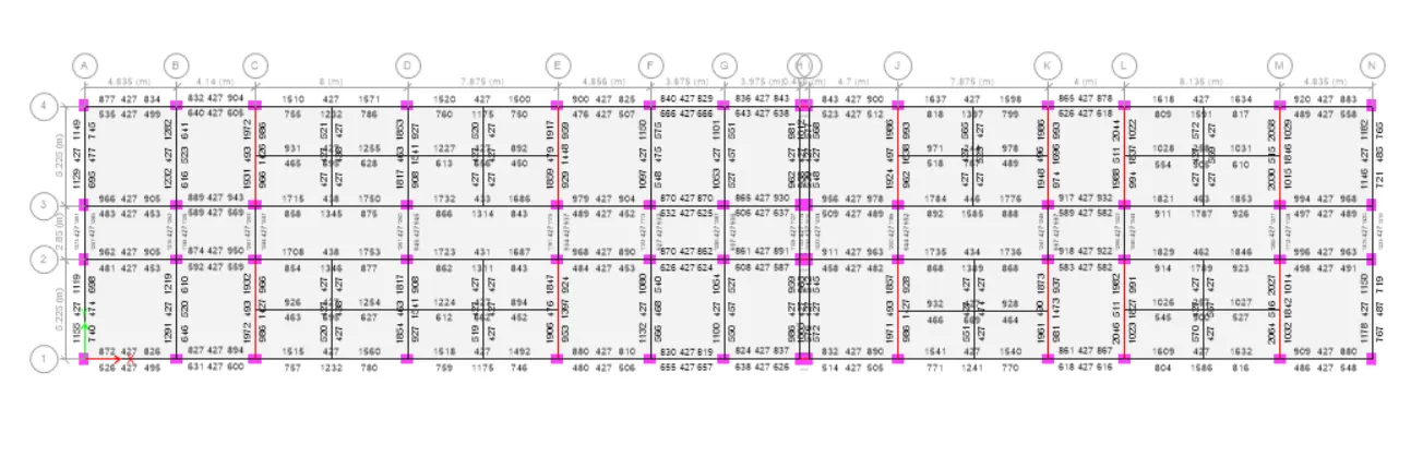
5. Go to concrete fram desugn and select the start design or check. and note down the value of reinforecement details
6. Select modal participating rations we have got that at mode 7 we have got above 90% so its ok
7. Now select the base reaction check Eqx, Eqy values should be same and Rsx and Rsy value aslo should be atleast equal toEqx. Eqy respectively if not then just take the Rsx values and divide it by Eq value whateveer the valuse will get that values needs to be multiplied in the load cases Rsx tab
8. Check for the shear walls go to base leevl click on reactiob Ex and Ey values will be available take these value and divide it be total base shear which should be greater than 90% if now add the shear wall is appropriate directions.
STEP-1:
STEP-2: (Material Properties)
1. M25 Grade of concrete
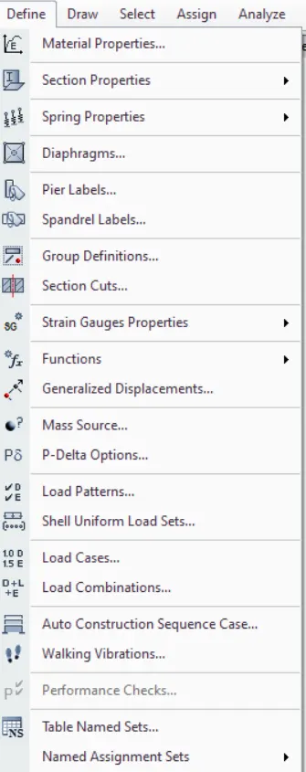
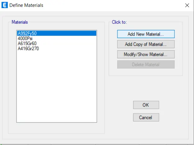
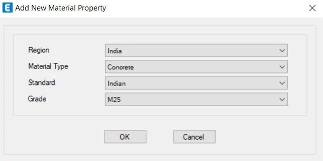
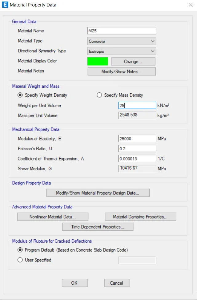
2. Rebar HYSD 415 and HYSD 500
STEP-3: (Section properties)
(Column Beam)
STEP-4: (Slab Section)
STEP-5: (Quick Draw columns)
STEP-6: (Quick Draw Beams)
STEP-7: (Quick Draw Slab)
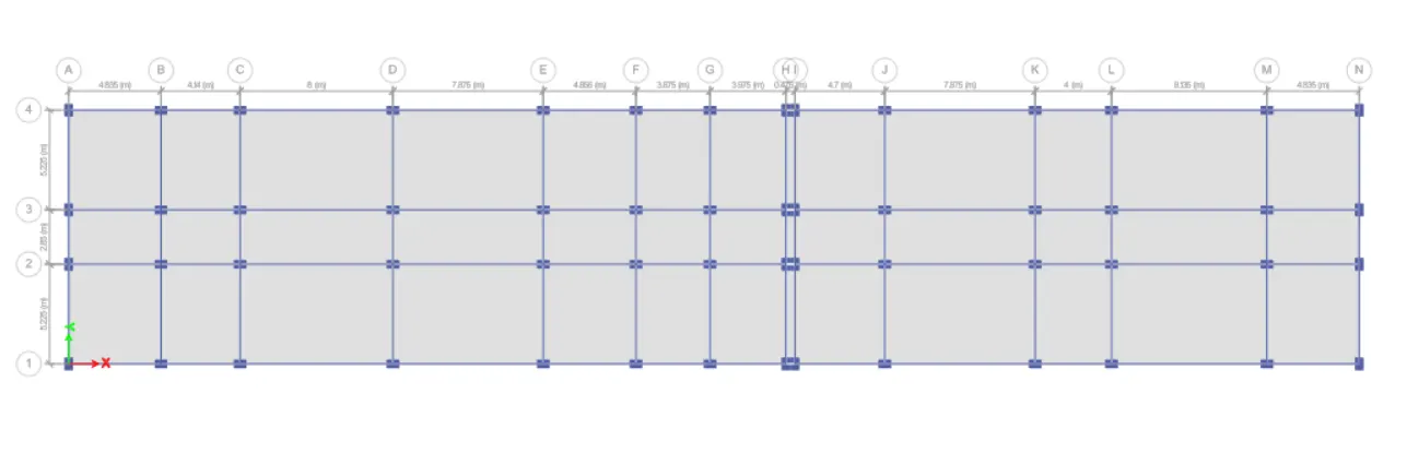
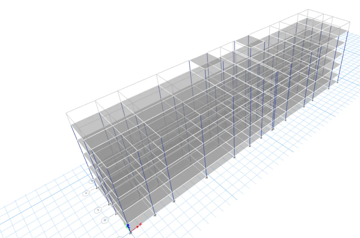
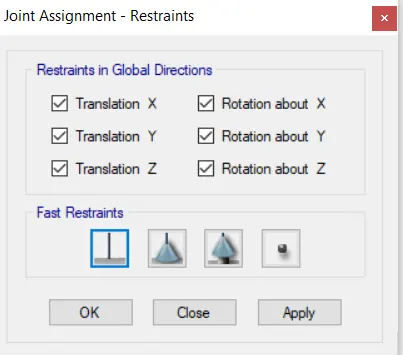
STEP-8: (Joint Assignment Restraints)
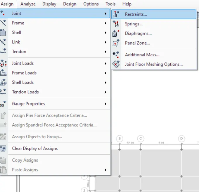
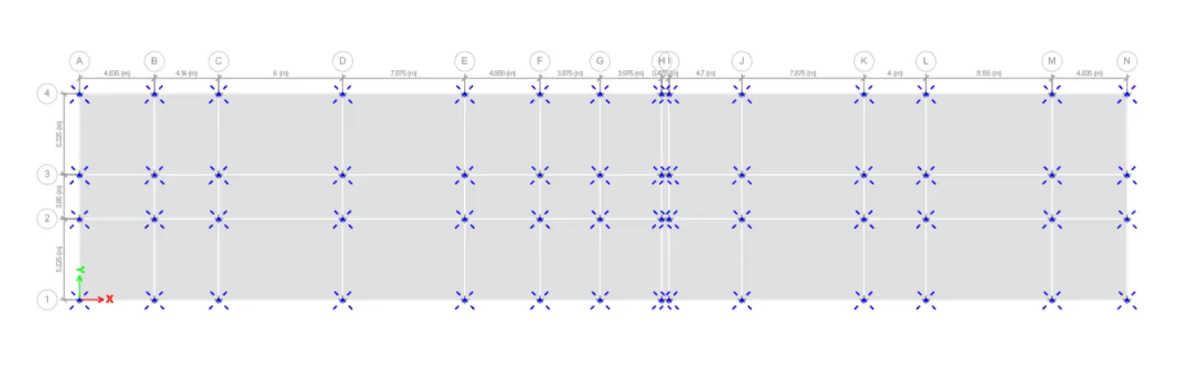
STEP-9: (Load Pattern)
STEP-10: (Load Cases)
MASS Source:
Frame Load Assignment - Distributed:


STEP-11
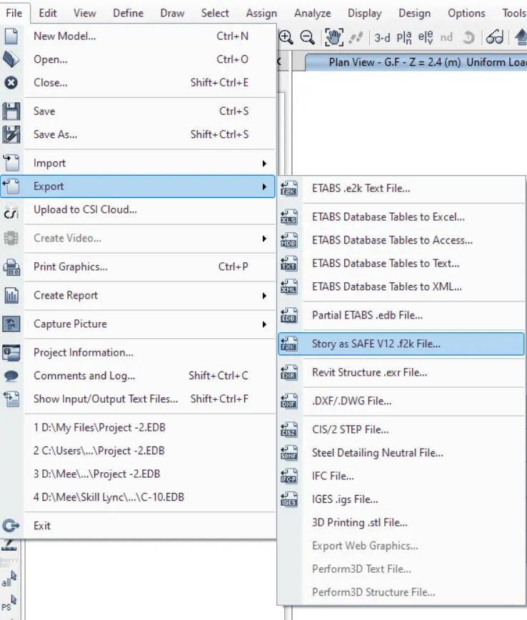
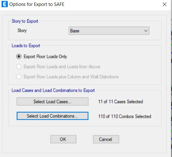
From ETABS model the column support loads are extracted by exporting the model base reaction to project file design of footing in SAFE software