Creation of geometries by Coordinate system methods using AutoCad
)Ans
Aim :
To create the geometers from P1 to P2 using all the coordinates system methods and P3 to P10 by any one coordinate system
To Draw the profile and the trusses using any coordinates system methods the dimensions are there for reference
INTRODUCTION:
Before going to the drawing we should know about the coordinates systems:
In Autocad there are two coordinate systems i. e cartesian and polar. to there coordinate systems the absolute and relative coordinates of relative coordinates of Autocad are applicable
Coordinate Systems:
Coordiante system is a system where numbers are used to determine the unique postion of point and or other geometeric elemnts aslo coordinate in Auotcad can be set by mouse input Setting the values of coordinates in the command line and entre coorrdinate using dynamic input
There are three types of coordinate systems they are :
1.Absolute Coordinate systems
2.Relative coordinate systems
a) Relative rectangular coordinates
b) Relative polar coordinates
3.Direct distance entry
1)Absolute Coordin ate system:
this System all points are established at some distance in the X & Y axis (Sometime Z - axis ) from a common origin (usally0,0)
2. Relative Coordinate system:
The loaction of relative coordinate is define by its distance from a refernce point in Autocad when using this system the first point of the drawing / geometry is alway absolute it is established with respect to orgina (0,0)
then all the suceessive position are esatablished with respect to thier preceding point this system is futher classified
a)Relative rectangular coordinate:
It is a coordinate system that specifices each point by a pair of numerical coordiante in the X - axis and Y - axis system the points succeding the first point are type in as @x,y in a command line
b)Relative polar coordinate:
This system specifies the distance (Length) and angleof a paricular point with respect to its previous point in the relative polar coordinate system point are established by typing A distance
3) Direct Distancve Entry :
It is another popular method used for drawing different shape geometry in Autocad the direct distance entry method enables the user to draw an object by simply pointing the cursar in the desired direction and entering the required distance the command line
Commands used:
1.Line command
2. Dimlinear command
3. Text command
4. Circle command
Procedure:
Staring Autocad Software
- Go to START MENU, select Autocad 2023
- Click on START DRAWING
- In the command line type in STARTUP (ENTER)
- Enter new value of startup : 1
- Go to application memu and select new
- In the Create New dialog box, select the imperial system in the start from scratch option
- Next select the decimal unit system from the advanced setup option
- Set the limits by entering LIMTIS in the command tab the lower left corner is specified as 0,0 and the upper - right corner is specified as 100, 100
A) To Create the geometries from P1 to P2 using all the coordinates system methods:
l . Drafting the geometry for P1 by using all coordinates system methods:
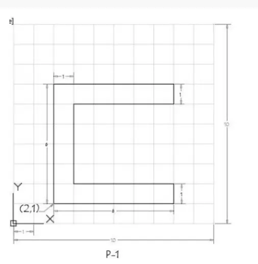
a) Absolute coordiante system:
1. Select the line tool from the ribbon tab or by entering the Line command in the command tab.
2. Specify the starting coordinate of point 1 as 2,1
3. Specify the next coordinate of point 2 as 8,1
4. Specify the next coordinate of point 3 as 8,2
5. Specify the next coordinate of point 4 as 3,2
6. Specify the next coordinate of point 5 as 3,6
7. Specify the next coordinate of point 6 as 8,6
8. Specify the next coordinate of point 7 as 8,7
9. Specify the next coordinate of point 8 as 2,7
10. Then for the last point click close on the command line
b) Relative Reactangular Coordinate system:
1. Select the line tool from the ribbon tab or by entering the Line command in the command tab.
2. Specify the starting coordinate of point 1 as 2,1
3. Specify the next coordinate of point 2 as @6,0
4. Specify the next coordinate of point 3 as @0,1
5. Specify the next coordinate of point 4 as @-5,0
6. Specify the next coordinate of point 5 as @0,4
7. Specify the next coordinate of point 6 as @5,0
8. Specify the next coordinate of point 7 as @0,1
9. Specify the next coordinate of point 8 as @-6,0
10. Then for the last point click close on the command line
C) Relative polar coordinatge system:
1. Select the line tool from the ribbon tab or by entering the Line command in the command tab.
2. Specify the starting coordinate of point 1 as 2,1
3. Specify the next coordinate of point 2 as @6<0
4. Specify the next coordinate of point 3 as @<190
5. Specify the next coordinate of point 4 as @5<180
6. Specify the next coordinate of point 5 as @4<90
7. Specify the next coordinate of point 6 as @5<0
8. Specify the next coordinate of point 7 as @1<90
9. Specify the next coordinate of point 8 as @6<180
10. Then for the last point click close on the command line
d) Direct Distamce Entry method:
1. Select the line tool from the ribbon tab or by entering the Line command in the command tab.
2. Specify the starting coordinate of point 1 as 2,1 in the command line
3. Specify the next coordinate of point 2 as 6 in the command line towards the +ve x - axis
4. Specify the next coordinate of point 3 as 1 in the command line towards the +ve y - axis
5. Specify the next coordinate of point 4 as 5 in the command line towards the -ve x - axis
6. Specify the next coordinate of point 5 as 4 in the command line towards the +ve y - axis
7. Specify the next coordinate of point 6 as 5 in the command line towards the +ve x - axis
8. Specify the next coordinate of point 7 as 1 in the command line towards the +ve y - axis
9. Specify the next coordinate of point 8 as 6 in the command line towards the -ve x - axis
10. Then for the last point click close on the command line
Result:
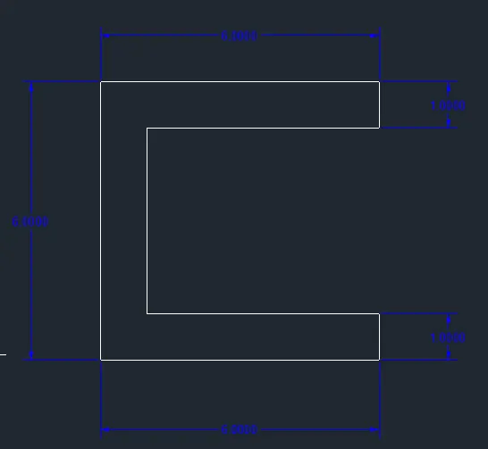
ll. Drafting the geometry for P2 by using all coordinates system methods:
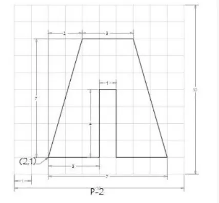
a) Absolute coordiante system:
1. Select the line tool from the ribbon tab or by entering the Line command in the command tab.
2. Specify the starting coordinate of point 1 as 2,1
3. Specify the next coordinate of point 2 as 5,1
4. Specify the next coordinate of point 3 as 5,5
5. Specify the next coordinate of point 4 as 6,5
6. Specify the next coordinate of point 5 as 6,1
7. Specify the next coordinate of point 6 as 9,1
8. Specify the next coordinate of point 7 as 7,8
9. Specify the next coordinate of point 8 as 4,8
10. Then for the last point click close on the command line
b) Relative Reactangular Coordinate system:
1. Select the line tool from the ribbon tab or by entering the Line command in the command tab.
2. Specify the starting coordinate of point 1 as 2,1
3. Specify the next coordinate of point 2 as @3,0
4. Specify the next coordinate of point 3 as @0,4
5. Specify the next coordinate of point 4 as @1,0
6. Specify the next coordinate of point 5 as @0,-4
7. Specify the next coordinate of point 6 as @3,0
8. Specify the next coordinate of point 7 as @-2,7
9. Specify the next coordinate of point 8 as @-3,0
10. Then for the last point click close on the command line
C) Relative polar coordinatge system:
1. Select the line tool from the ribbon tab or by entering the Line command in the command tab.
2. Specify the starting coordinate of point 1 as 2,1
3. Specify the next coordinate of point 2 as @3<0
4. Specify the next coordinate of point 3 as @4<190
5. Specify the next coordinate of point 4 as @5<90
6. Specify the next coordinate of point 5 as @1<90
7. Specify the next coordinate of point 6 as @4<270
8. Specify the next coordinate of point 7 as @3<0
9. Specify the next coordinate of point 8 as @3<180
10. Then for the last point click close on the command line
d) Direct Distamce Entry method:
1. Select the line tool from the ribbon tab or by entering the Line command in the command tab.
2. Specify the starting coordinate of point 1 as 2,1 in the command line
3. Specify the next coordinate of point 2 as 3 in the command line towards the +ve x - axis
4. Specify the next coordinate of point 3 as 4 in the command line towards the +ve y - axis
5. Specify the next coordinate of point 4 as 1 in the command line towards the -ve x - axis
6. Specify the next coordinate of point 5 as 4 in the command line towards the +ve y - axis
7. Specify the next coordinate of point 6 as 3 in the command line towards the +ve x - axis
8. Enter the length of point 7 as 7 in the command at an angle of < 106 from the =+ve x - axis while keeping polar tracking on
9. Enter the length of point 8 as 3 in the command line towards the - ve x - axis
10. Then for the last point click close on the command line
Result:
lll. Drafting the geometry for P4 by using absolute coordinate system:
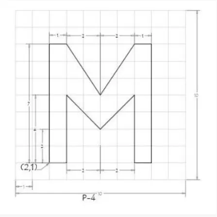
Steps :
- Select the line tool from the ribbon tab or by entering the line command in the command tab
- Specify the next coordinate of point as 2,1
- Specify the next coordinate of point as 3,1
- Specify the next coordinate of point as 3,5
- Specify the next coordinate of point as 5,3
- Specify the next coordinate of point as 7,5
- Specify the next coordinate of point as 7,1
- Specify the next coordinate of point as 8,1
- Specify the next coordinate of point as 8,8
- Specify the next coordinate of point as 7,8
- Specify the next coordinate of point as 5,5
- Specify the next coordinate of point as 3,8
- Specify the next coordinate of point as 2,8
- Then for the last point click close on the command line
Result:
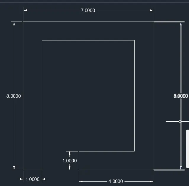
lv. Drafting the geometry for P5 by using relative rectangular coordinate system:
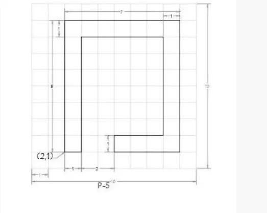
Steps:
- Select the line tool from the ribbon tab or by entering the line command in the command tab
- Specify the starting coordinate of point 1 as 2,1
- Specify the next coordinate of point 2 as @1,0
- Specify the next coordinate of point 3 as @ 0,7
- Specify the next coordinate of point 4 as @5,0
- Specify the next coordinate of point 5 as @0,-6
- Specify the next coordinate of point 6 as @-3,0
- Specify the next coordinate of point 7 as @ 0,-1
- Specify the next coordinate of point 8 as @ 4,0
- Specify the next coordinate of point 9 as @0,8
- Specify the next coordinate of point 10 as @-7,0
- Then for the last point click close on the command line
Results:
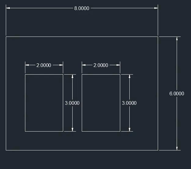
V Drafting the geometry for P7 by using Absolute coordinate system:
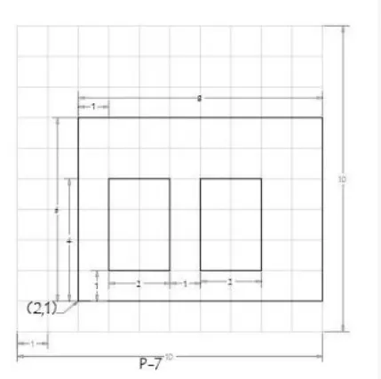
Steps:
- Select the line tool from the ribbon tab or by entering the line command in the command tab
- Specify the starting coordinate of point 1 as 2,1
- Specify the next coordinate of point 2 as 10,1
- Specify the next coordinate of point 3 as 10,7
- Specify the next coordinate of point 4 as 2,7
- Click close on the command line
- Select the line tool from the ribbon tab or by entering the line command in the command tab
- Specify the starting coordinate of point 5 as 3,2
- Specify the next coordinate of point 6 as 5,2
- Specify the next coordinate of point 7 as 5,5
- Specify the next coordinate of point 8 as 3,5
- Click close on the command line
- Select the line tool from the ribbon tab or by entering the line command in the command tab
- Specify the starting coordinate of point 9 as 6,2
- Specify the next coordinate of point 10 as 8,2
- Specify the next coordinate of point 11 as 8,5
- Specify the next coordinate of point 12 as 6,5
- Then for the last point click close on the command line
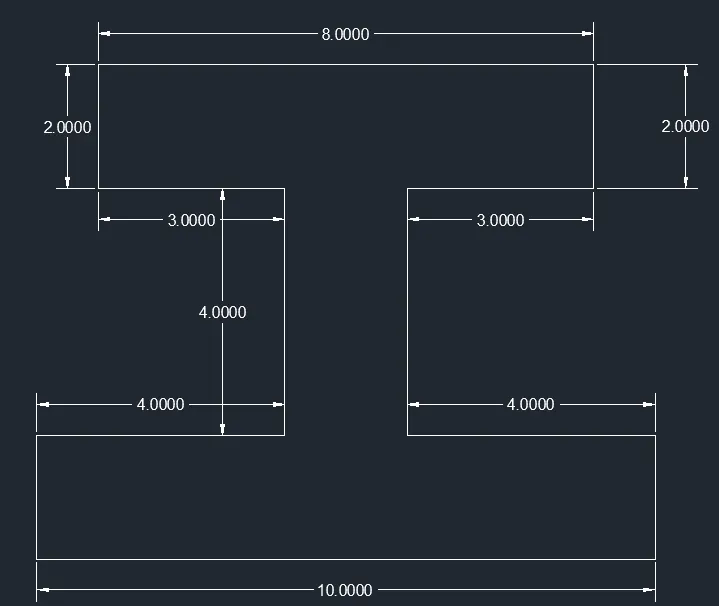
Vl Draft the geometry for the P8 by using relative rectangular coordinate system:
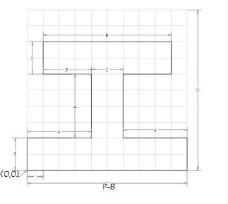
Steps:
- Select the line tool from the ribbon tab or by entering the line command in the command tab
- Specify the next coordinate of point 1 as 0,0
- Specify the next coordinate of point 2 as @10,1
- Specify the next coordinate of point 3 as @0,2
- Specify the next coordinate of point 4 as @-4,0
- Specify the next coordinate of point 5 as @0,4
- Specify the next coordinate of point 6 as @3,0
- Specify the next coordinate of point 7 as @0,2
- Specify the next coordinate of point 8 as @-8,0
- Specify the next coordinate of point 9 as @0,-2
- Specify the next coordinate of point 10 as @3,0
- Specify the next coordinate of point 11 as @0,-4
- Specify the next coordinate of point 12 as @ -4,0
- Then for the last point click close on the command line
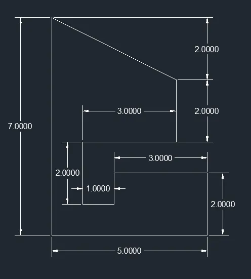
Vll Drafting the geometry for P9 by using Absolute Coordinate systems:
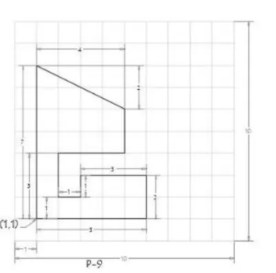
Steps:
- Select the line tool from the ribbon tab or by entering the line command in the command tab
- Specify the starting coordinate of point 1 as 1,1
- Specify the next coordinate of point 2 as 6,1
- Specify the next coordinate of point 3 as 6,3
- Specify the next coordinate of point 4 as 3,3
- Specify the next coordinate of point 5 as 3,2
- Specify the next coordinate of point 6 as 2,2
- Specify the next coordinate of point 7 as 2,4
- Specify the next coordinate of point 8 as 5,4
- Specify the next coordinate of point 9 as 5,6
- Specify the next coordinate of point 10 as 1,8
- Then for the last point click close on the command line
Vlll Drafting the geometry P10 by using relative polar coordinate system:
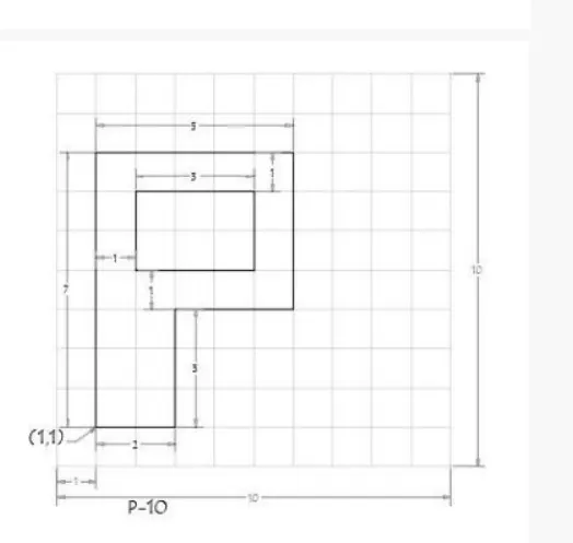
Steps:
- Select the line tool from the ribbon tab or by entering the line command in the command tab
- Specify the starting coordinate of point 1 as 1,1
- Specify the next coordinate of point 2 as @2<0
- Specify the next coordinate of point 3 as @3<90
- Specify the next coordinate of point 4 as @3<0
- Specify the next coordinate of point 5 as @4<90
- Specify the next coordinate of point 6 as @5<180
- Click close on the command line
- Specify the starting coordinate of point 7 as 2,5
- Specify the next coordinate of point 8 as @3<0
- Specify the next coordinate of point 9 as @2<90
- Specify the next coordinate of point 10 as @3<180
- Then for the last point click close on the command line
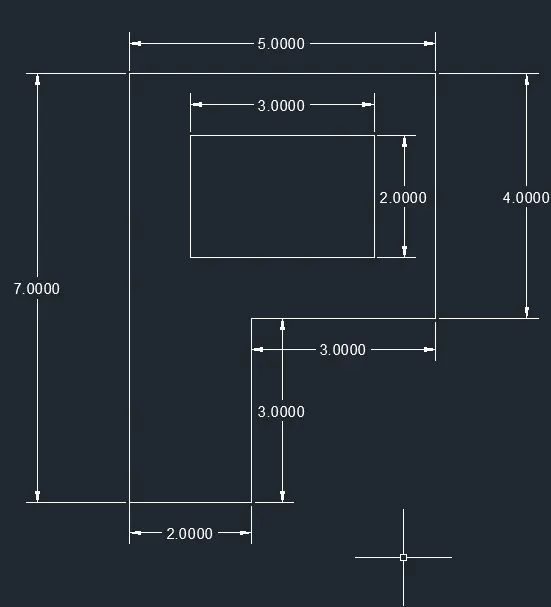
(B) To Draw the profile and the trusess using any coordinate system methods. the diamensions there for reference :
l. Drafting the wood profiler as shown in the given picture :
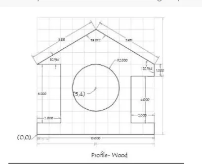
Step for creating the wood profile using direct distance entry methods:
1. Select the line tool from the ribbon tab or by entering the line command in the command tab
2. Specify the starting coordinate of point 1 as 0,0 in the command line
3.Enter the length of point 2 as 10 in the command line toward the +ve x - axis
4.Entra the length of point 3 as 1 in the command line toward the +ve y -axis
5. Entra the length of point 4 as 2 in the command line toward the -ve x - axis
6. Entra the length of point 5 as 4 in the command line toward the +ve y -axis
7.Entra the length of point 6 as 2 in the command line toward the +ve x -axis
8.Entra the length of point 7 as 1 in the command line toward the +ve y -axis
9.Entra the length of point 7 as 5.831 in the command line at an angle of < 149.036 from +ve x -directiona while keeping polar tracking on
10.Entra the length of point 7 as 5.831 in the command line at an angle of < 210.964 from +ve x -directiona while keeping polar tracking on/
11. Entra the length of point 9 as 2 in the command line towards the +ve x -axis
12. Entra the length of point 10 as 5 in the command line towards the -ve y - axis
13. Entra the length of point 11 as 2 in the command line towards the +ve x - axis
14. Click close on the command line
15. Select the circle tool by entering the circle command in the command tab
16. Specify center point of the circle as 5,4
17. Specify radius of the circle as 2
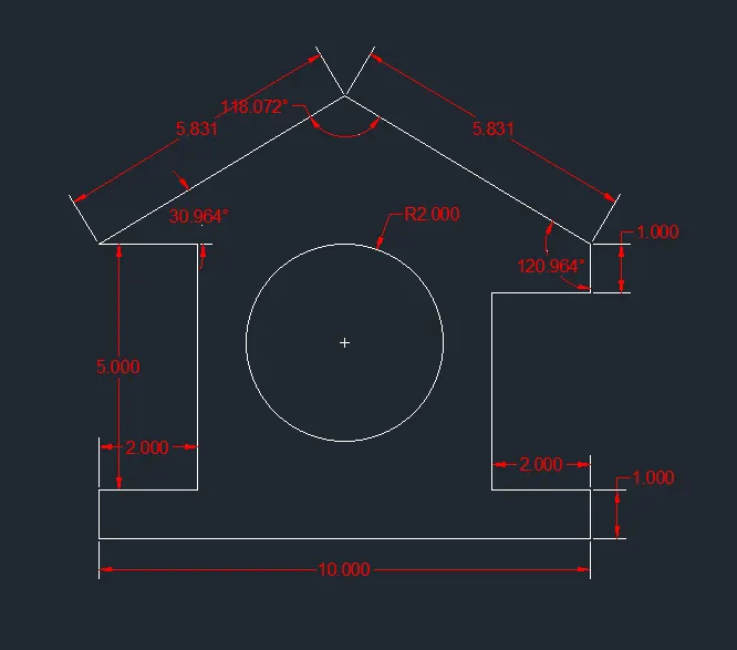
ll. Drafting the queen post truss as shown in the given image:
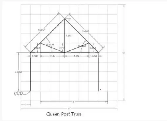
Step for creating the wueen post truss using realtive polar coordinate system:
1. Select the line tool from the ribbon tab or by entering the line command in the command tab
2. Specify the next coordinate of point 1 as 1,1
3.Specify the next coordinate of point 2 as @4<90
4.Specify the next coordinate of point 3 as @5<45
5.Specify the next coordinate of point 4 as @5<315
6.Specify the next coordinate of point 5 as @4 < 270
7.Press ESC to cancel the line command
8. Select the line tool again from the ribbon tab by entering the line command in the command tab
9.Specify the starting coordinate of point 1 as 1,5
10. Specify the next coordinate of point 2 as @1<0
11. Specify the next coordinate of point 3 as @2.5355<0
12. Specify the next coordinate of point 4 as @2.5355<0
13. Specify the next coordinate of point 5 as @1<0
14.Press ESC to cancle the line command
15.Select the line tool again from the ribban tab entering the line command in the command tab
16.Specify the starting coordinate of point 1 as 2,5
17.Specify the next coordinate of point 2 as @1<90
18.Specify the next coordinate of point 3 as @2.7256<338
19.Specify the next coordinate of point 4 as @2.7256<22
20.Specify the next coordinate of point 5 as@ 1<270
21.Press ESC to cancle the line command
22. Select the line tool again from the ribban tab entering the line command in the command tab
23. Specify the next coordinate of point 1 as 4.5,5
24. Specify the next coordinate of point 2 as @3.5371<90
25 Press ESC to cancle the line command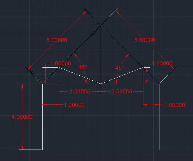
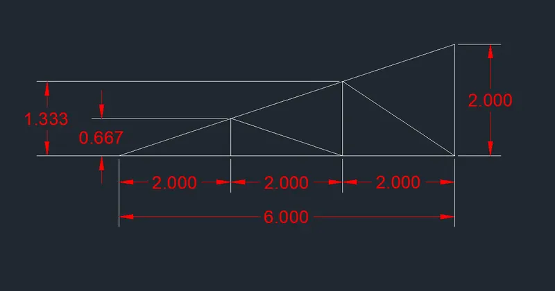
lll.Drafting the mono pitch as shown in the given image:
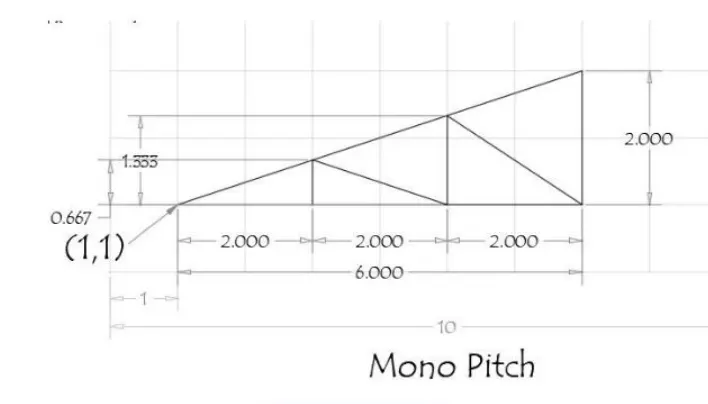
Steps for creating the mono pitch using Absolute coordinate system:
1. Select the line tool from the ribbon tab or by entering the line command in the command tab
2. Specify the starting coordinate of point 1 as 1,1
3.Specify the next coordinate of point 2 as 7,1
4.Specify the next coordinate of point 3 as 7,3
5.Click close on the command line
6. Select the line tool again from the ribbon tab or by entering the line commandin the command tab
7.Specify the next coordinate or point 4 as 3,1
8. Specify the next coordinate or point 5 as 3,1.667
9.Specify the next coordinate or point 6 as 5,1
10. Specify the next coordinate or point 7 as 5,2.333
11. Specify the next corrdinate of point 8 as 7,1
12 Press ESC to cancel the line command.