Project 2_Design & Analysis of a Hostel building at Guwahati, Assam
Aim:
- To Model, analyse, design, and prepare the construction drawings from the provided architectural drawing of a G+3 Hostel building.
- To design foundation detail illustrating the pile and pile cap reinforcement, Tie Beam details connecting the pile caps, Column reinforcement, framing plan for the typical floor, and Beam reinforcements for the ground floor.
Introduction: Computational analysis and design of multi-storey buildings have become a lot easier with the use of modern software tools like ETABS. The software helps fasten the design process and assists from the very first phase of modelling till the detailing process. At the same time, the accuracy and precision achieved through these computational tools are unmatched.
Procedure :
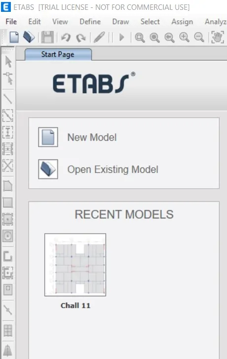
- Open the ETabs software.
- Click the file menu and choose to create a new model option.
- After choosing a new model a dialogue box will appear as Model Initialization.
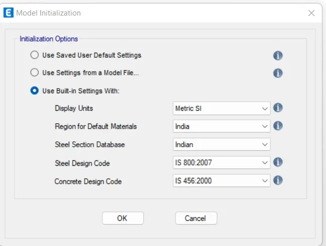
- Choose the built-in settings option and select the display units and codes.
- New dialogue box will appear named New Model Quick Templates.
- Select Custom Grid spacing and custom story data.
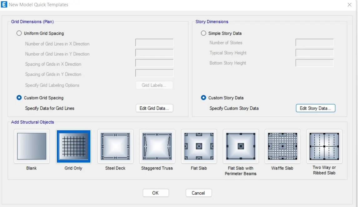
- After models initialization, select grid and storey inputs from new model quick templates dialog box.
- In the dialogue box choose grid spacing and custom story data which is used to provide the input specified above.
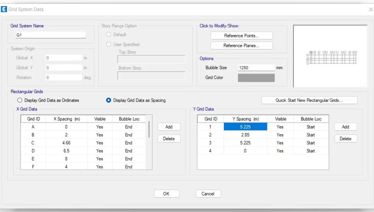
- Now edit stories by using the user-defined story input, 26 stories are incorporated
- Storey 1 has been labelled as a master storey and all above levels are labelled similar to that.
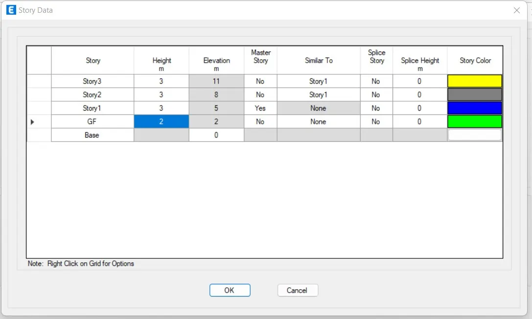
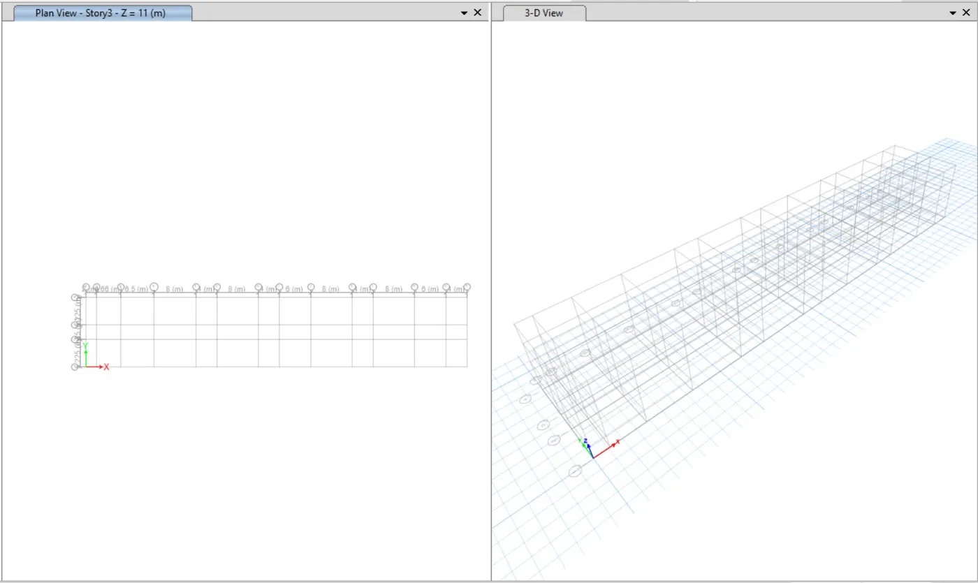
- So, 3 storeys are successfully added in the project.
- Create alll the storeys as similar to storey 1.
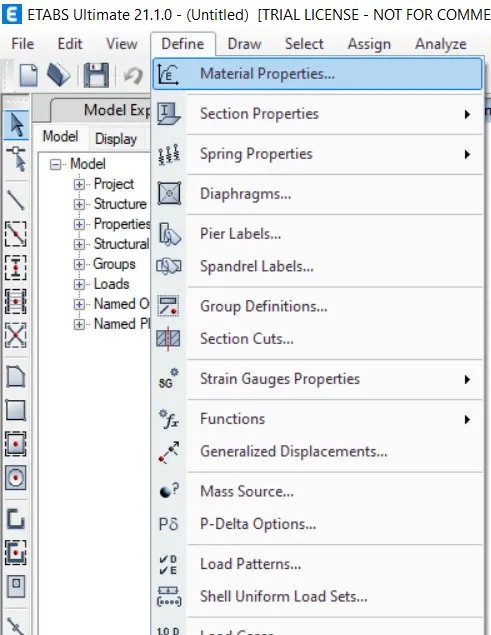
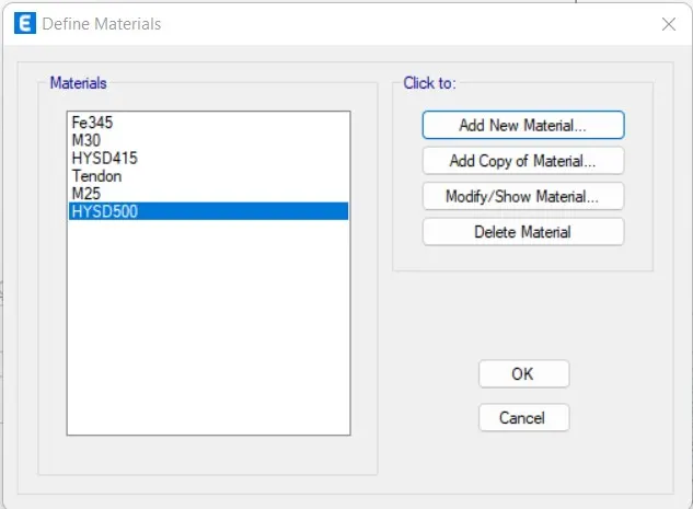
- Select Material properties under define tab.
- New dialogue box will appear named Define Materials.
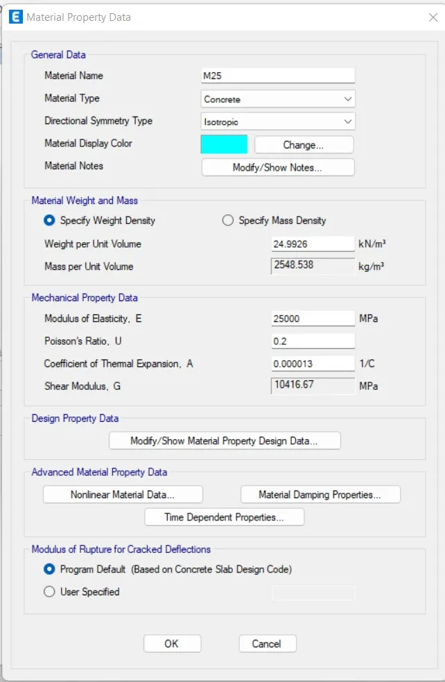
- Now need to add material type as concrete and grade as M25.
- Now we need to check the material property data, as shown below.
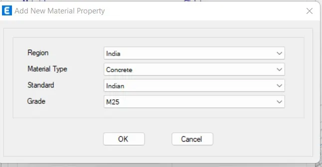
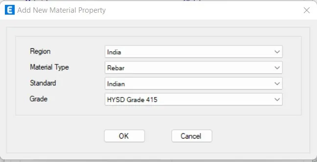
- Now need to add material type as rebar and grade as HYSD 415.
- Now we need to check the material property data
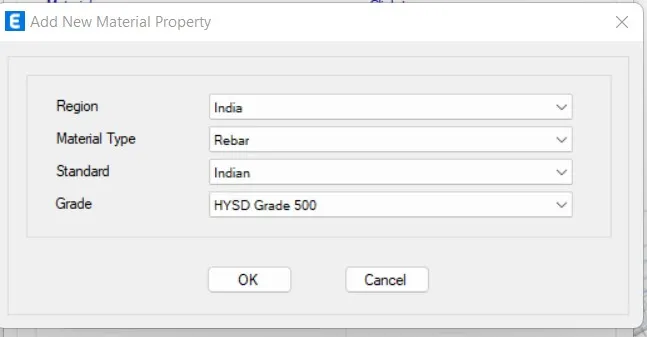
- Now need to add material type as rebar and grade as HYSD 500.
- Now we need to check the material property data
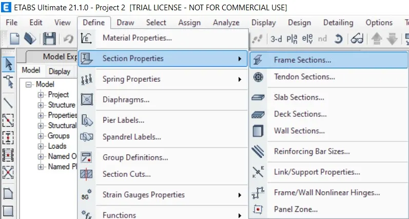
- Now select Section Properties under Define Tab.
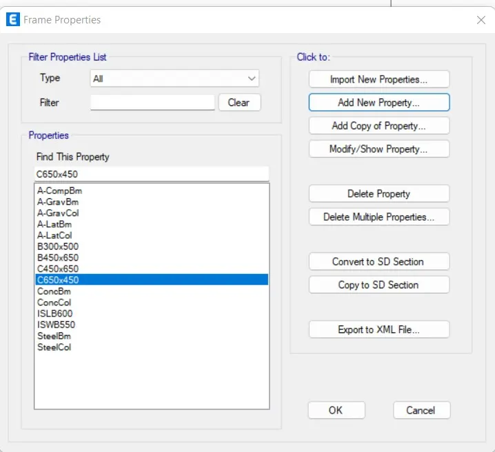
- Select Frame Sections and Select Add new properties in Frame Properties.
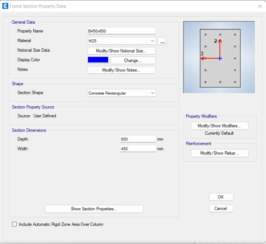
- Create a new Property as a beam and input values as 450X650.
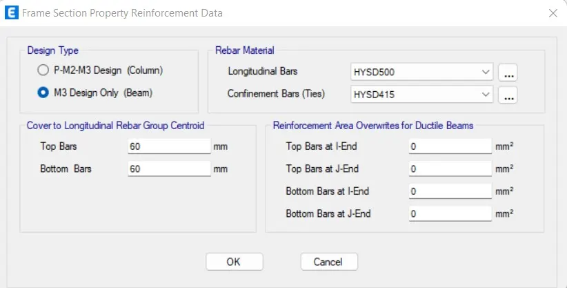
- Select Modify/Show Rebar in Reinforcement option.
- Select M3 Design only (Beam) and Select Reabar as HYSD415.
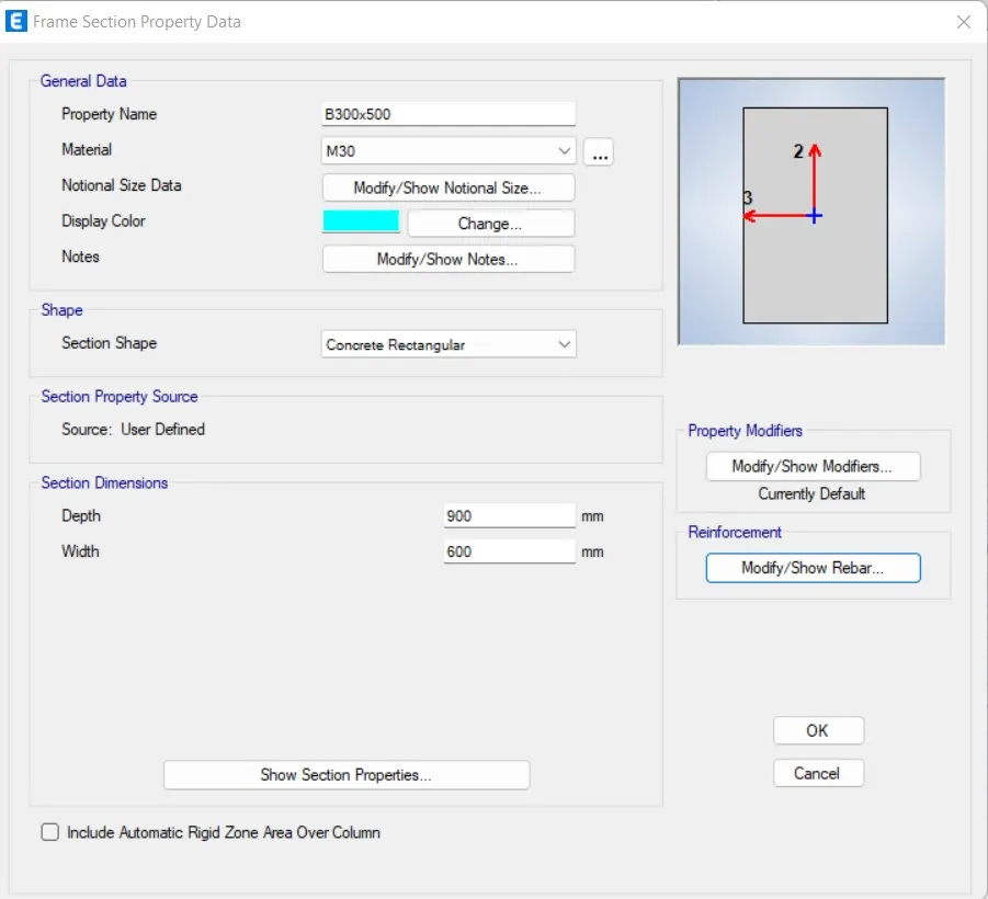
- Create a new Property as a beam and input values as 300X500.
- Select Modify/Show Rebar in Reinforcement option.
- Select M3 Design only (Beam).
- Select Reabar as HYSD415.
- Create a new Property as a column and input values as 450X650.
- Select Modify/Show Rebar in Reinforcement option.
- Select P-M2-M3 Design (Column) and Select Reabar as HYSD415.
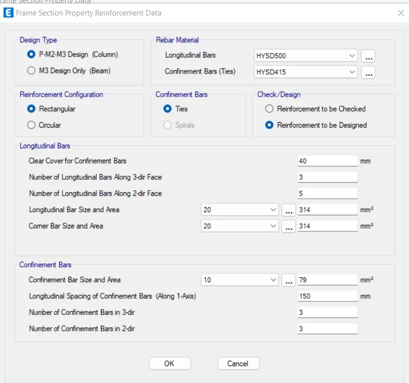
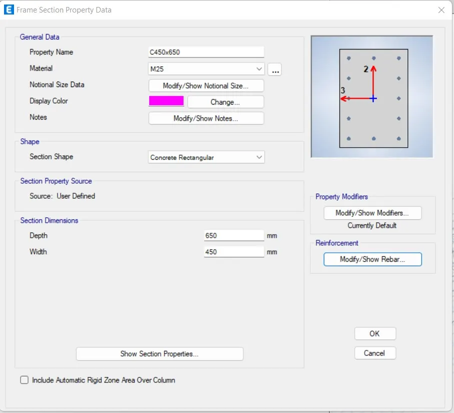
- Create a new Property as a column and input values
- Select Modify/Show Rebar in Reinforcement option.
- Select P-M2-M3 Design (Column) and Select Reabar as HYSD415.
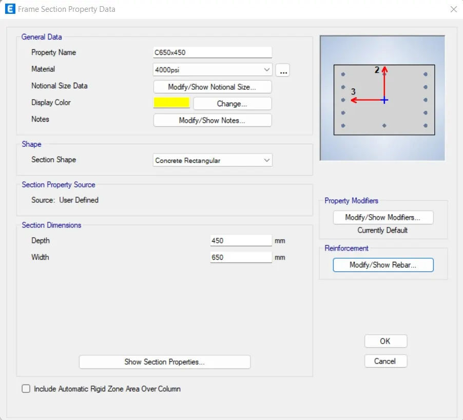
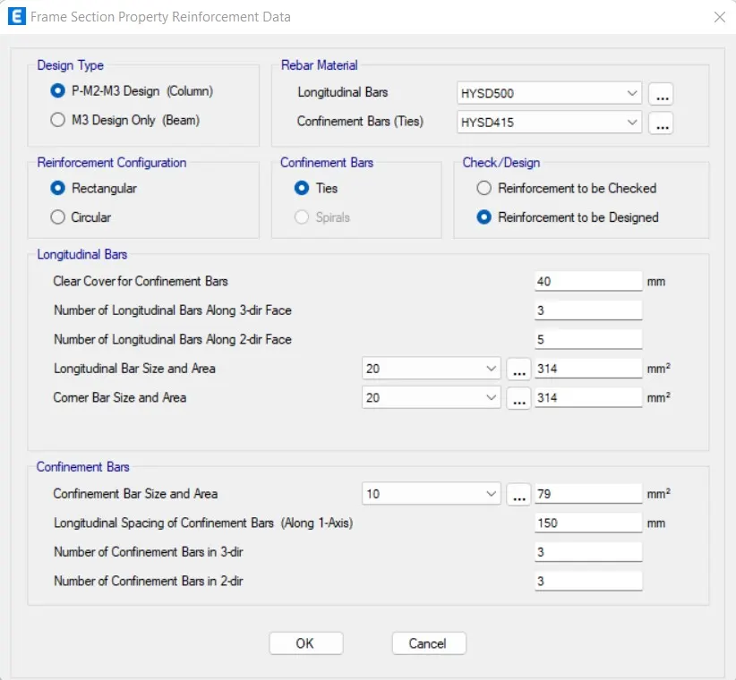
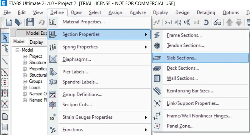
- Now select Section Properties under Define Tab.
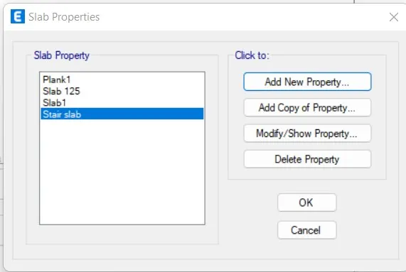
- Select Slab Sections and Select Add new properties in Slab Properties.
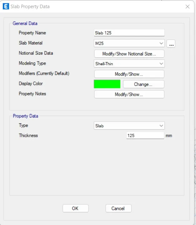
- Using the membrane properties, slab size 125 mm has been added to the list.
- Membrane property will help to consider only slab weights and Floor weights in analysis of structure while no stiffness component of flange advantage are considered during calculation.
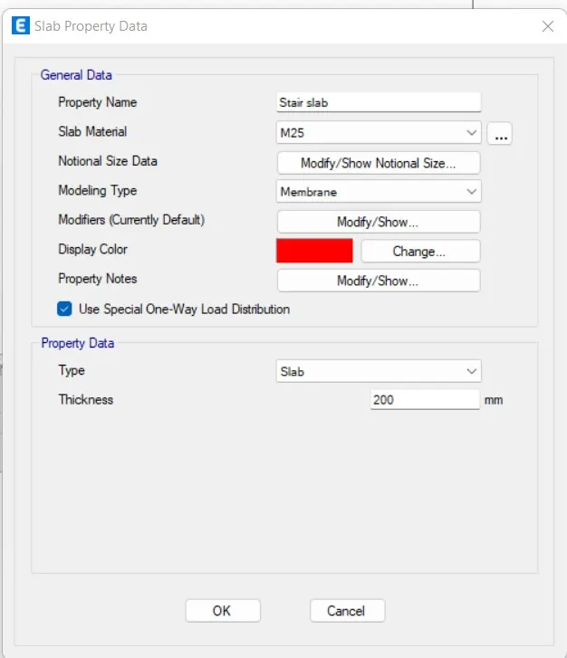
- Using the membrane properties, slab size 200 mm has been added to the list for staircase.
- Membrane property will help to consider only slab weights and Floor weights in analysis of structure
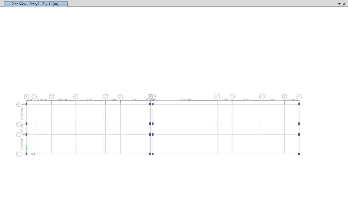
- Now Draw columns of size 450X650mm at the intersection of the horizontal and vertical grids and beams
- Now draw columns of size 650X400 mm at the intersection of the horizontal and vertical grids and beams
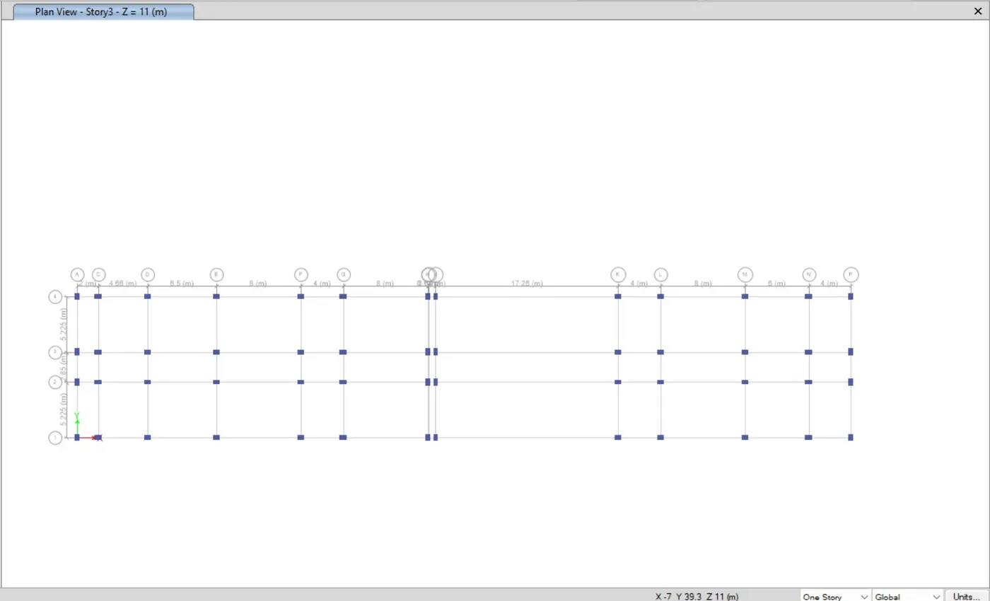
- Columns are Successfully added to the structure.
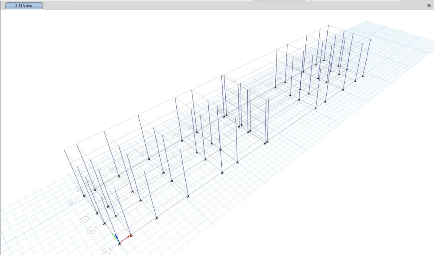
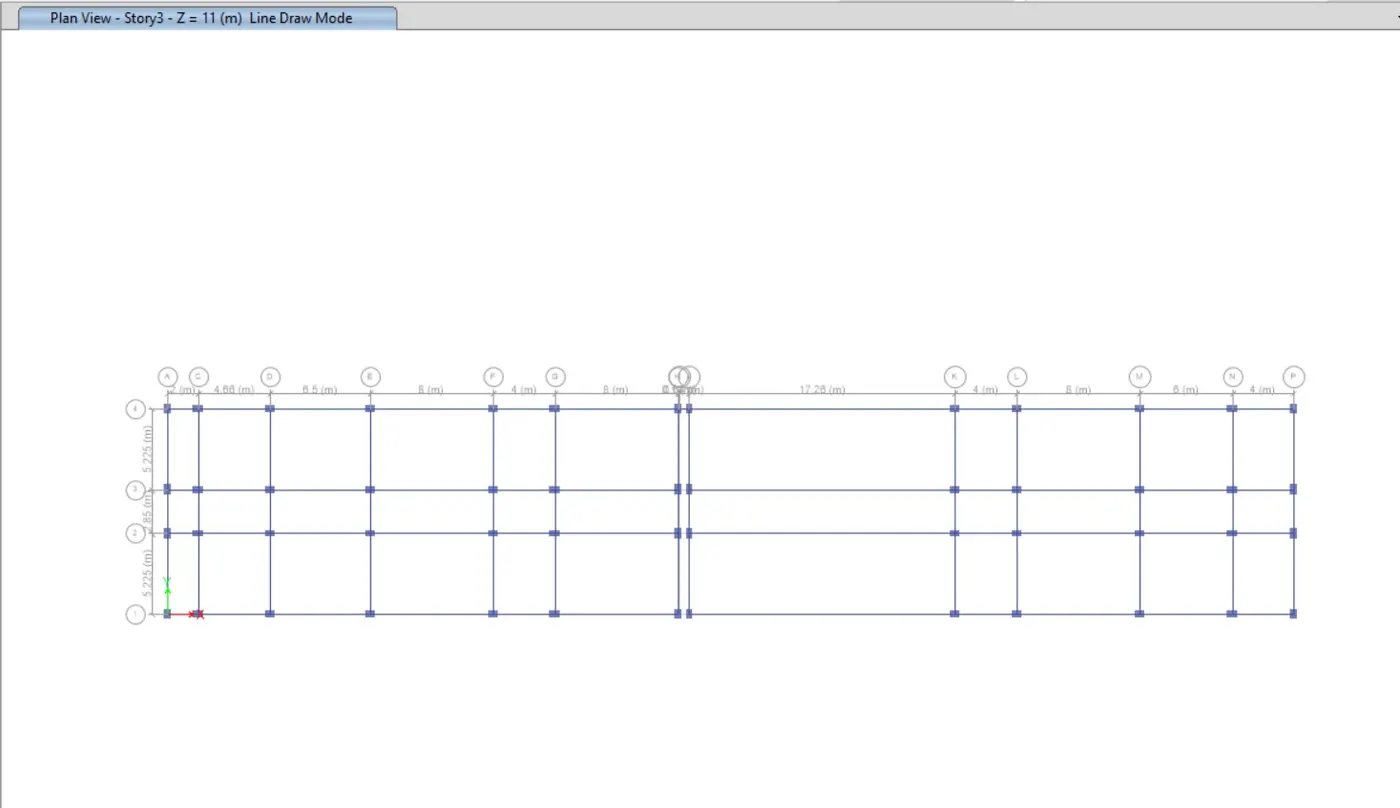
- Now Draw the Beams.
- Draw beams of size 450X650mm at the intersection of the horizontal and vertical grids and beams with quick draw beam keeping all the stories on.
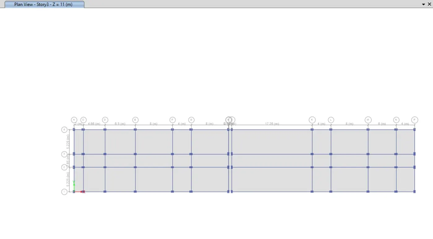
- Now Draw the Slab.
- Draw slab of size 125mm thickness, Draw slabs with quick draw floor/wall keeping all the stories on.
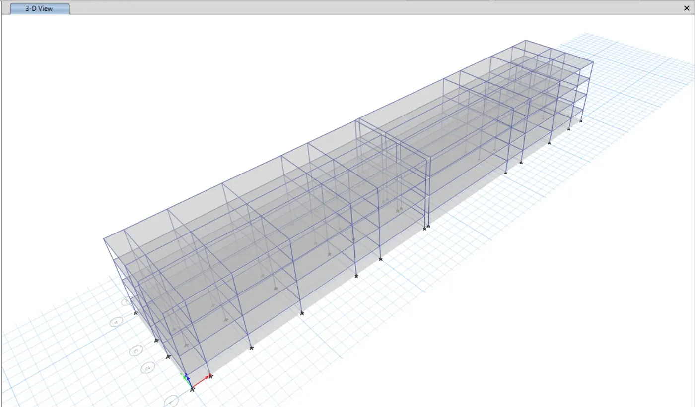
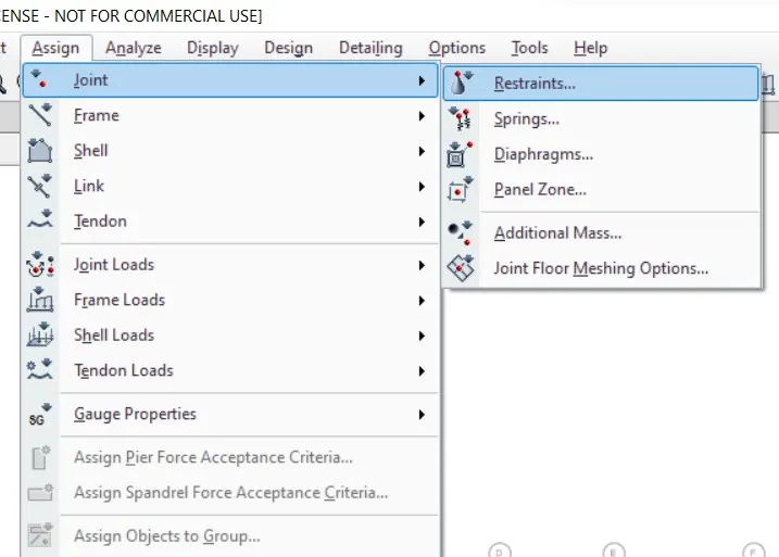
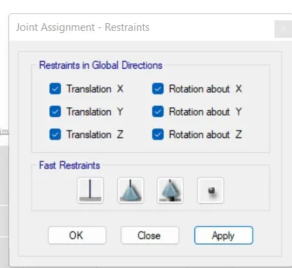
- Now we go to base plan and select all the joints.
- Now we select the Restraint from joint option
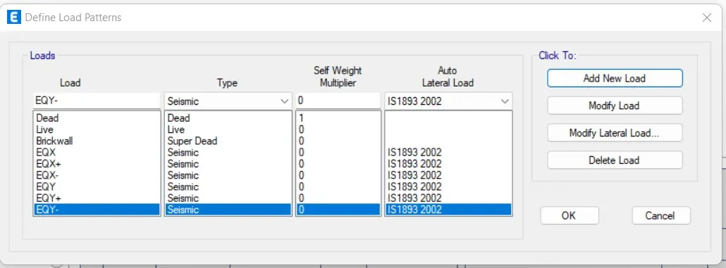
- Now define the Load patterns.
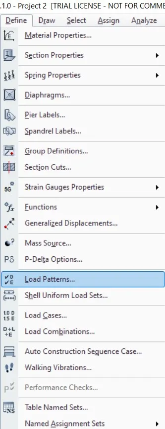
- Click on the define tab and click on load patterns.
- Define the loads like dead load, live load, brick load, earthquake load in X direction and same loads in Y direction
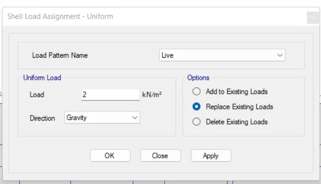
- Next we have to click on assign option and then select shell loads and select Uniform option.
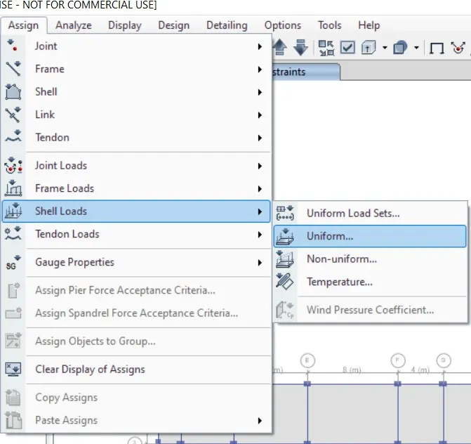
- Here we apply 2 Kn/m2 live load for the staircase portion, verandah and liftcore area.
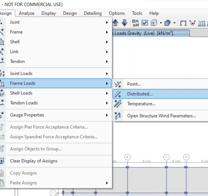
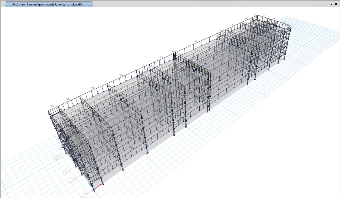
- Next we need to select the distributed load from the frame loads.
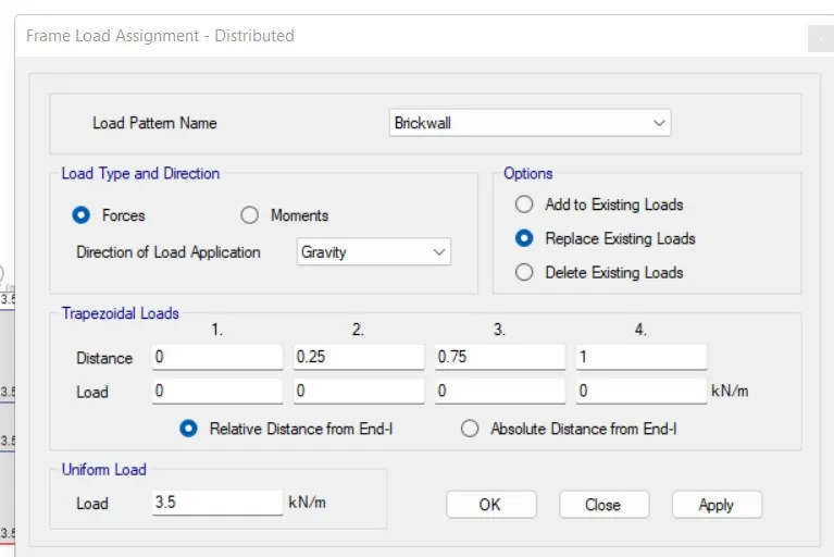
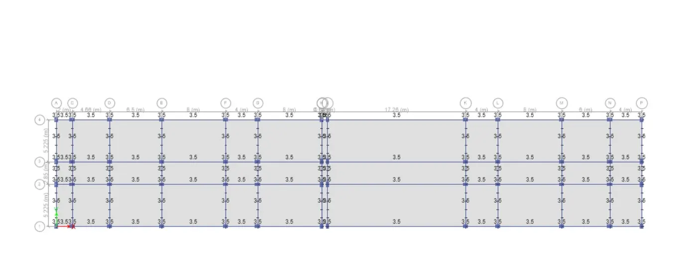
- Then after the new tab will appear, in that case we select load pattern as Brickwall and we take uniform load as 3.5 Kn/m and then apply.
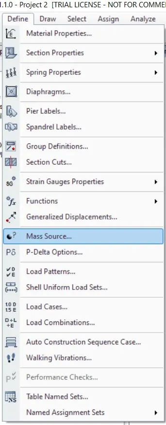
- Now go to Mars Source from define tab.
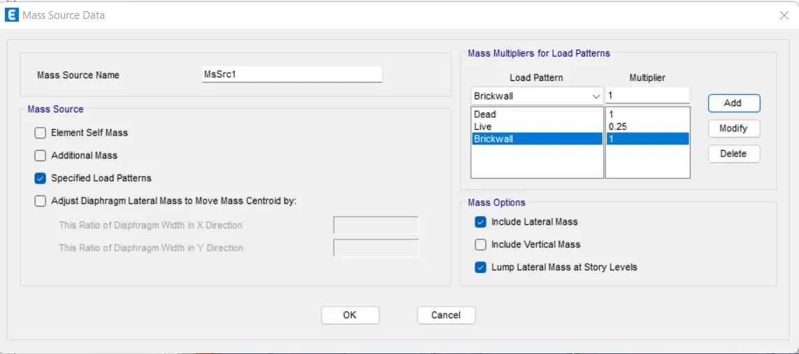
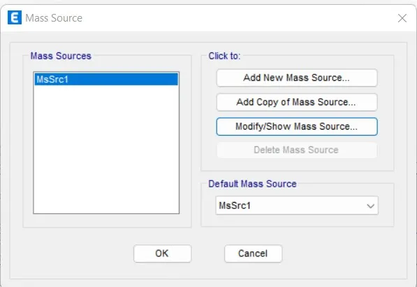
- Modify the mars source and tick mark the required loads and Add load patterns and assign the model.
- Now go to Load cases in define Tab.
- Now create the Diaphragm by going to the assign tab then shell and select diaphragm.
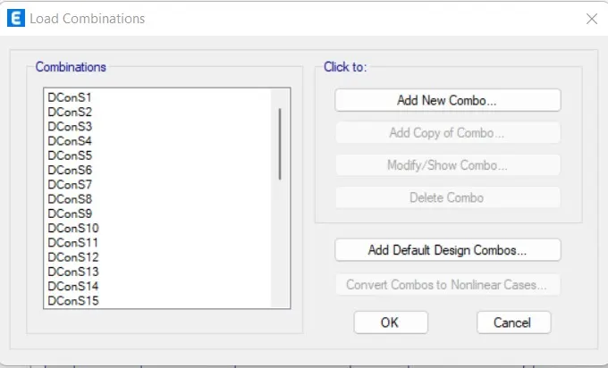
- Now go to Load combinations in define Tab.
- Select add default design combos and Select concrete frame Design.
- Next run the analysis
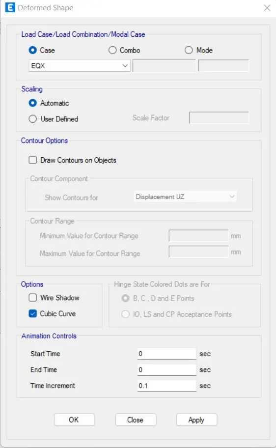
- After Run analysis, We select Show deformed Shape Option.
- We select Earthquake load in that.
- Next we see the deformed shape of structure with Earthquake loads.
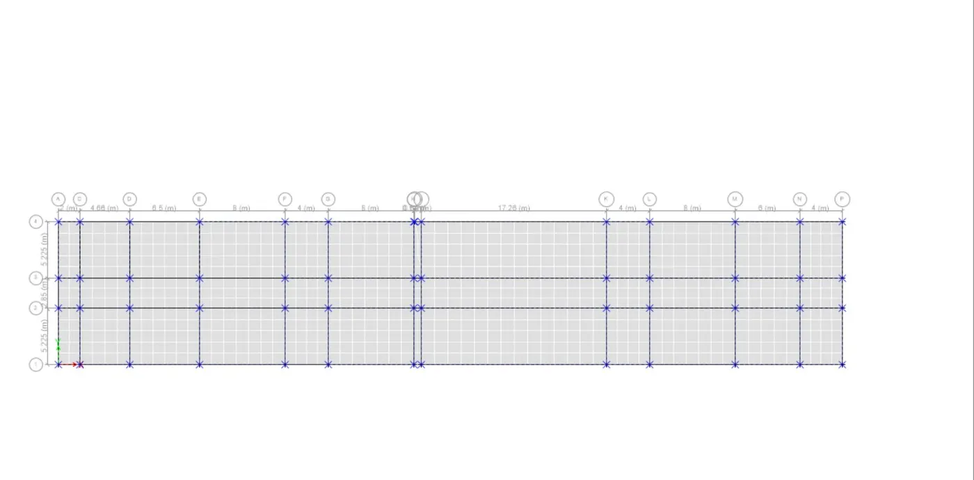
- Next we have to start the beam design by selecting 'start design/check' option
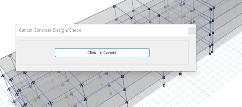
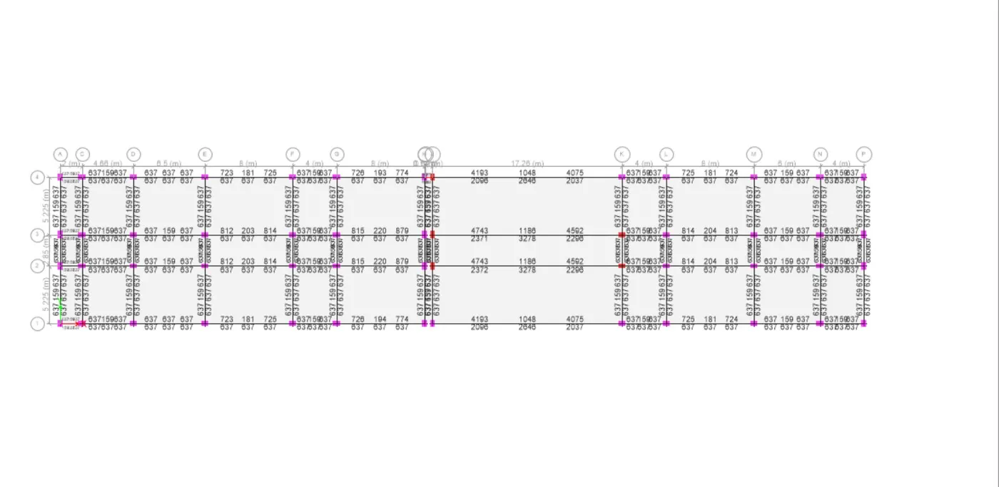
- After the completion of beam design, we need to select the 'Display Design information'
- After selecting the 'Display Design info' option the new tab appears, in that we select the longitudinal reinforcement in the design output and click on the ok button
- Next the longitudinal reinforcement details will appear
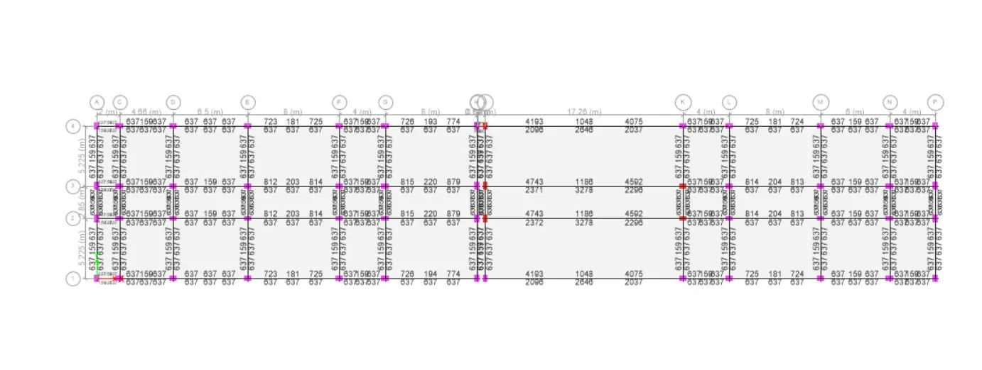
- Now we need to draw the reinforcement diagram of 7-span continuous along Grid-1 and also need to provide the reinforcement details.
- Now from the Elevation view, we can see details of column Reinforcement.
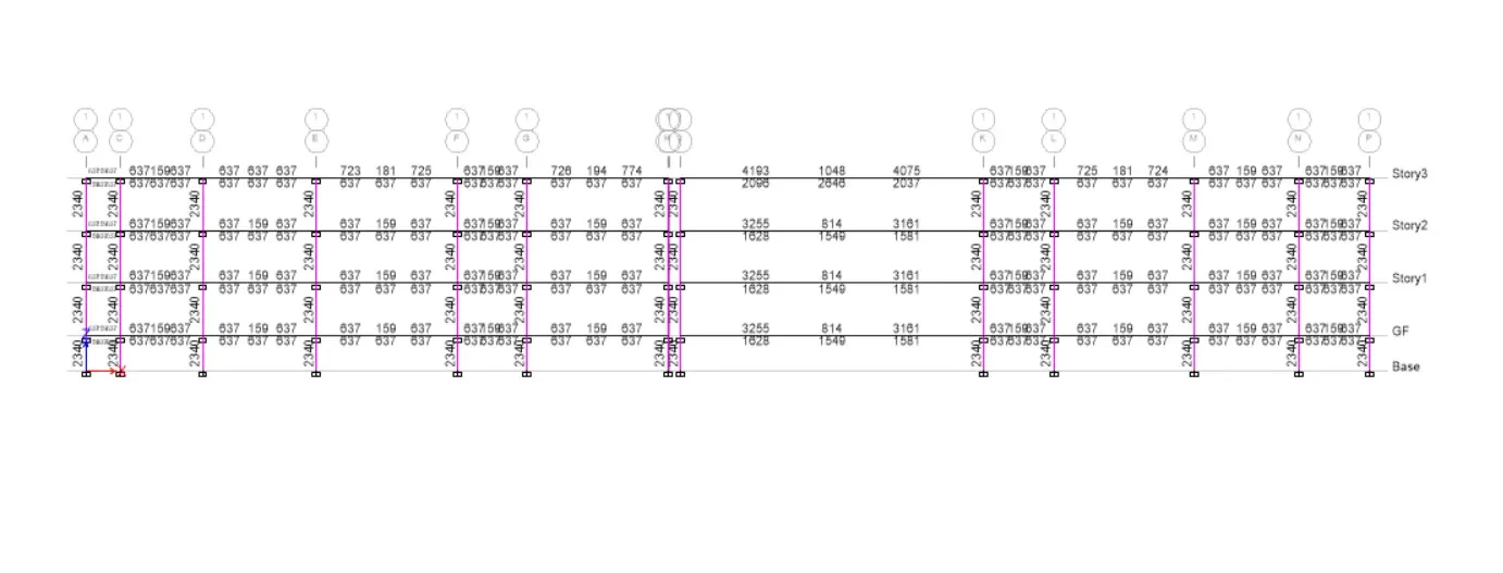
- Here we take column 1-L for Reinforcement.
- Next we have to export the base floor loads and loads from above to SAFE .
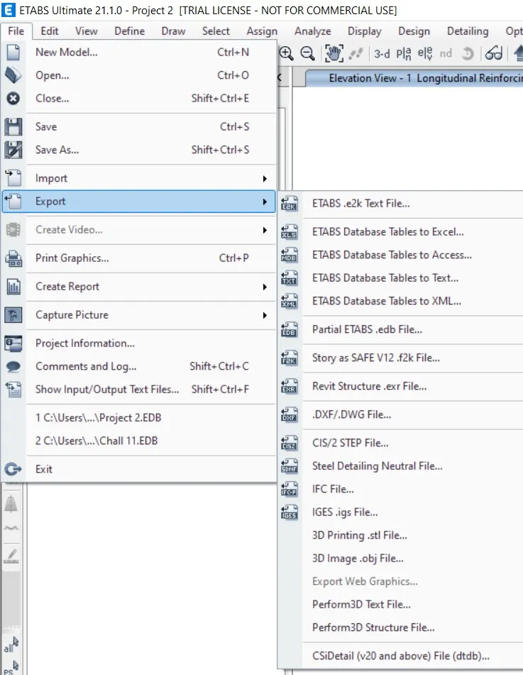
- Next we have to open the safe 2016 and import the f2k file.
- Then the file has been opened in safe
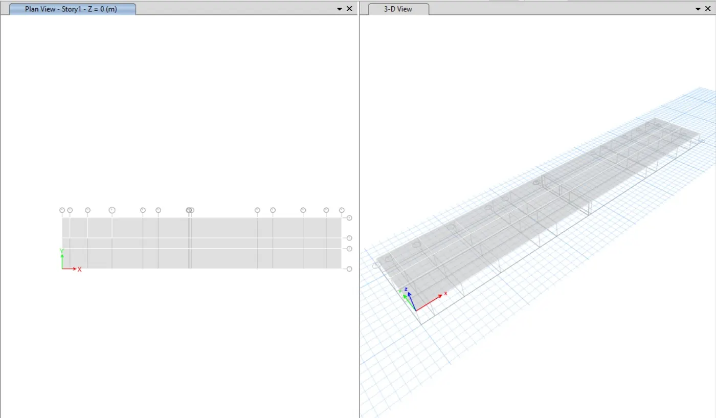
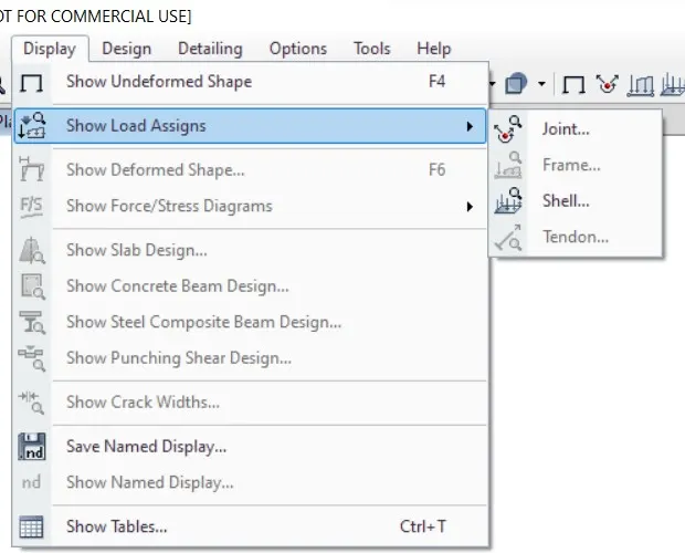
- We select the show loads from the display option
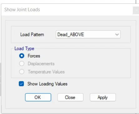
- After selecting the show load options, and the new tab will be visible, in that we select to dead_above as load pattern.
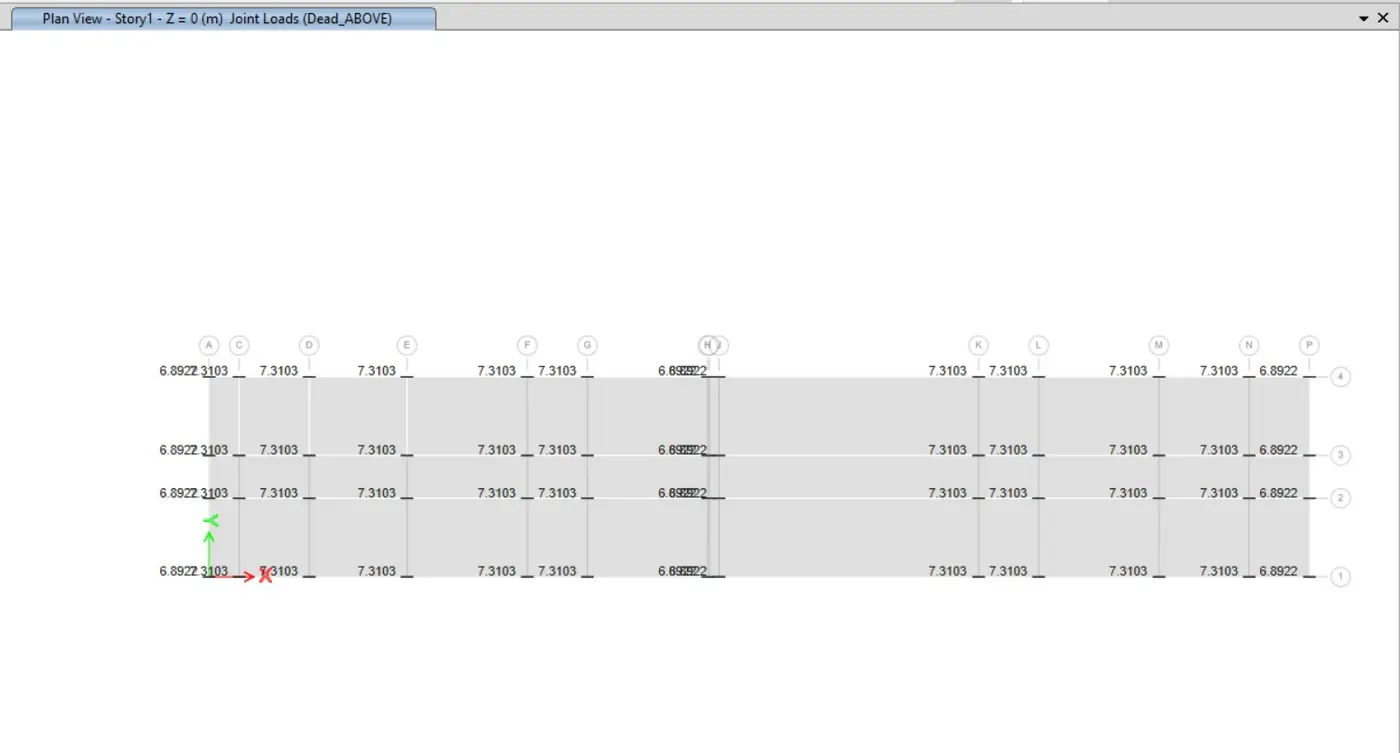
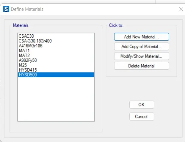
- Next we selected materials from the define option to assign the material.
- After selecting the materials the new tab appears, then we add new materials by selecting the add new materials options.
- Now we need to add material type as concrete and grade as M25.
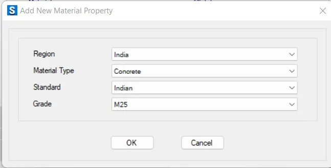
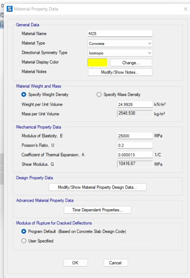
- Now we need to add material type as rebar and grade as HYSD 500.
- Now we need to add material type as rebar and grade as HYSD 415.
- So, materials are assigned.
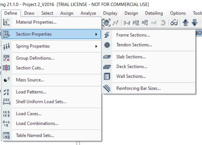
- Now select Section Properties under Define Tab.
- Select Slab Sections and Select Add new properties in Slab Properties.
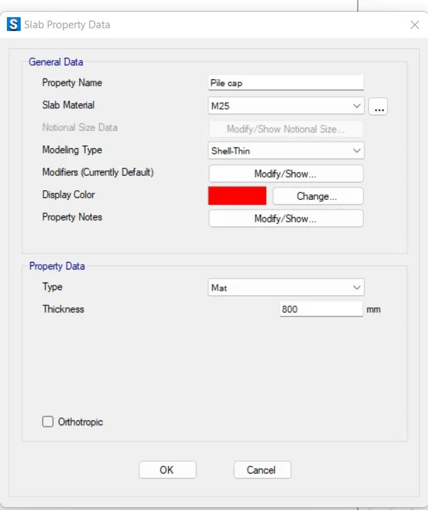
- After Selecting the new property, name the slab property as Pile_cap.
- We put the slab thickness as 800mm ans material as M25.
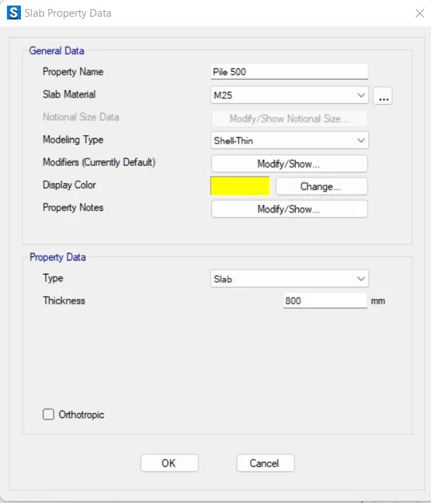
- After Selecting the new property, name the slab property as Pile_500.
- We put the slab thickness as 800mm ans material as M25.
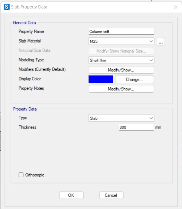
- We have to add another slab propery as Column_stiff.
- We put the slab thickness as 800mm ans material as M25.
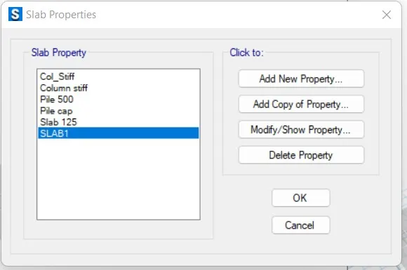
- Slab properties are assigned Successfully.
- Now we are transfering this model to the 2016 version because of smooth Results.
- Pile caps are assigned as shown below.
- The piles are assigned with 500 mm diameter.
- The columns are assigned with the size of (450 mm x 650 mm) and (650 mm X 450 mm).
- Select “Quick Draw Area around point”
- Draw Piles with the property as “Pile500” at appropriate positions
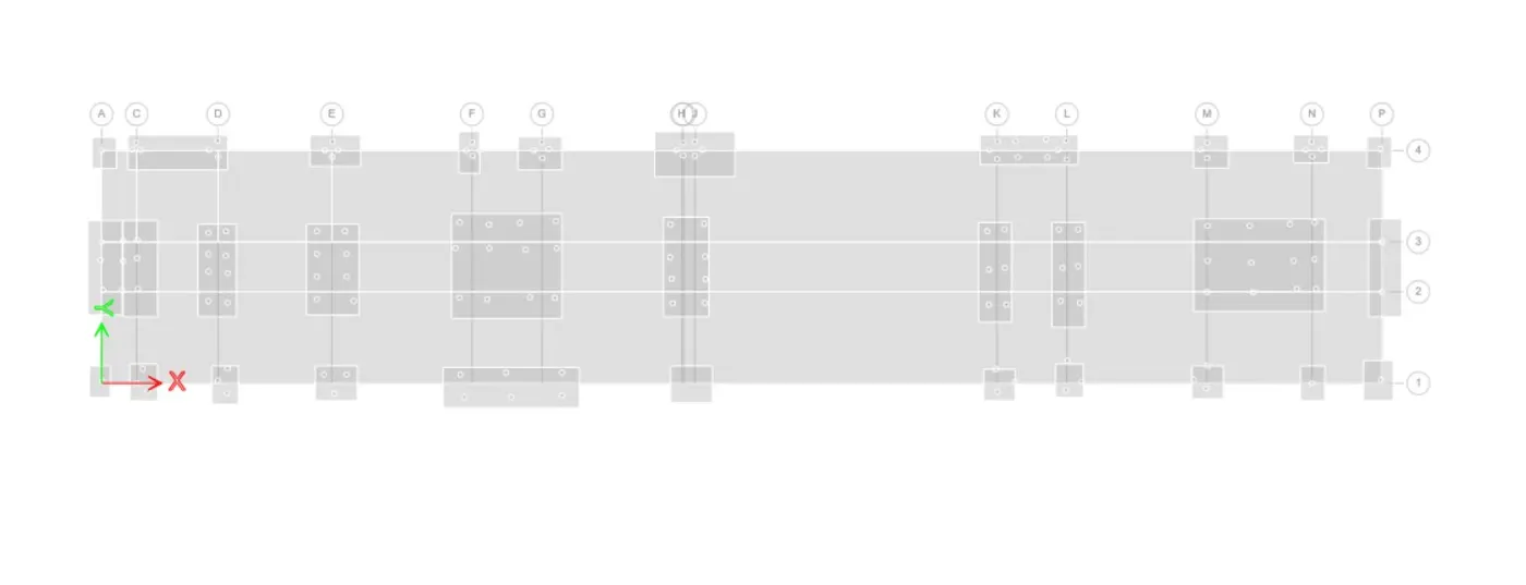
- Select all joints of Pile Sttiff and assign point spring
- Go to Assign> Joint> Springs
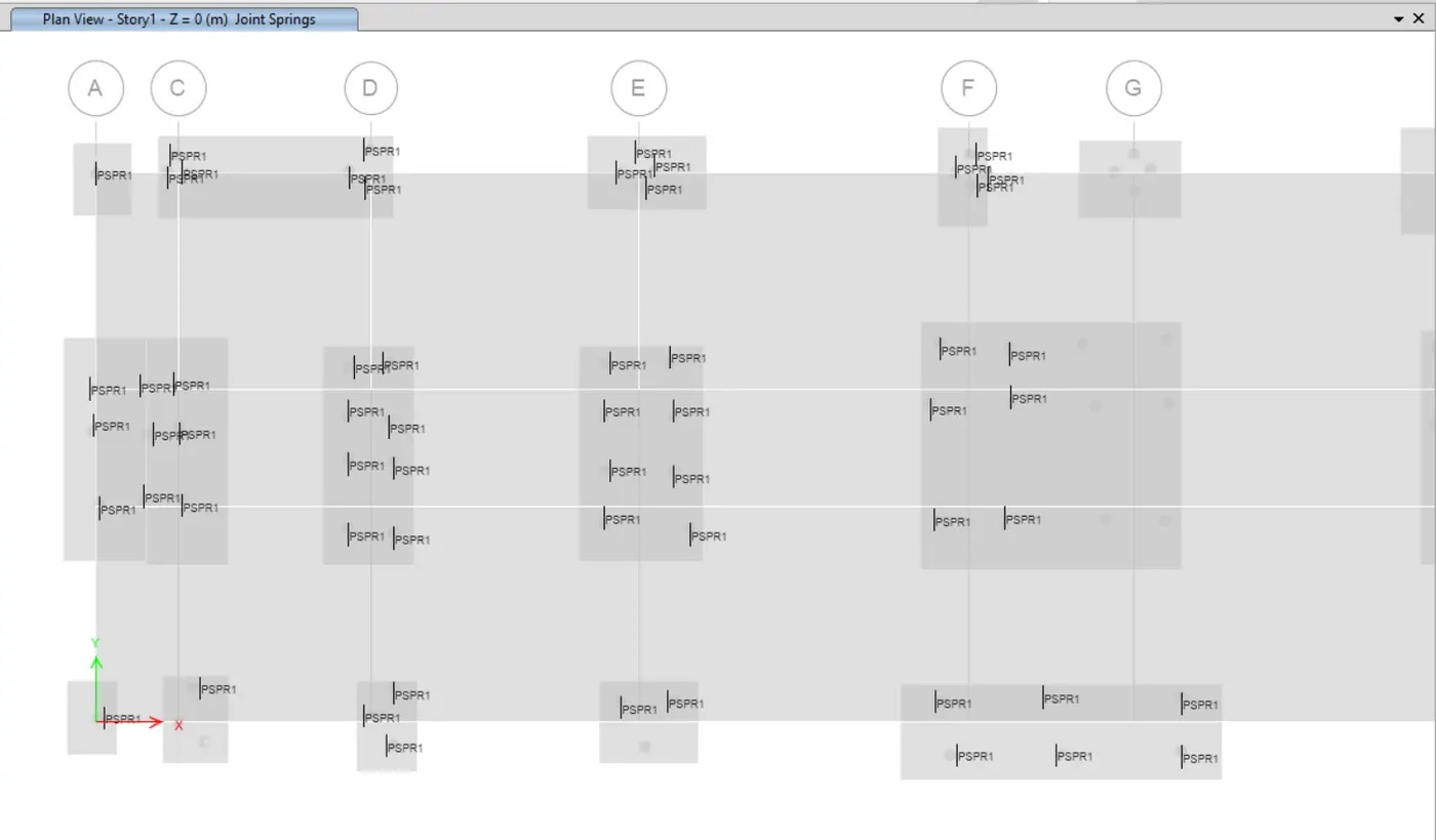
- We select the points to assign the springs for the piles.
- Now we select the springs from the support data from assign option.
- Next point spring properties tab will be visible.
- Next we select the modifiy/show property, then the new tab appears. We take for 490.87 in translational z.
- Point springs are assigned successfully.
- We have to assign the point load from the column.
- Now we select the point loads from the load data from assigned option.
- Next the point load tab will be visible, in that we add the gravity load at Z-direction as 1071.53 KN.
- Next we enter the size of punching shear as (650X450 mm).
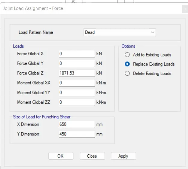
- Point loads are assigned to the column successfully.
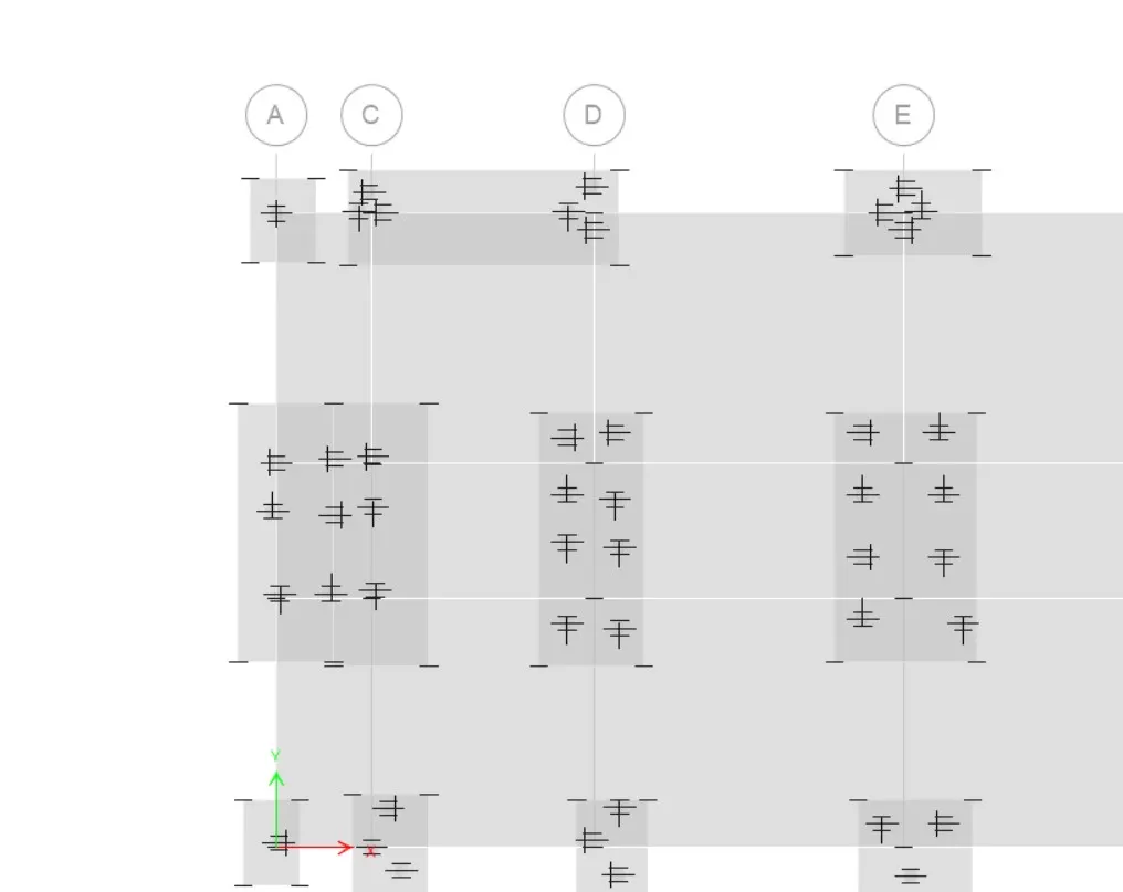
- Next we right click on the pile cap the new tab appears.
- In that we need to check the rebar material whether the fe500 is assigned or not, if not we change to every Fe500.
- We need to check all the pile caps.
- Now we need to Run the Analysis.
- The deformed shape will be visible after completion of Run Analysis.
- From the display option we select show reactions forces.
- After selecting the reaction forces option the new day will be visible, in that we put the load cases as Dead.
- Next click on the apply button.
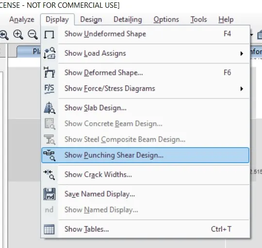
- Next from the display option we select the punching shear design.
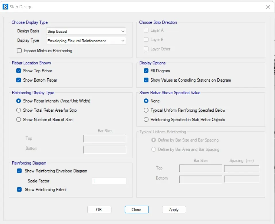
- Next, we select shoe slab design.
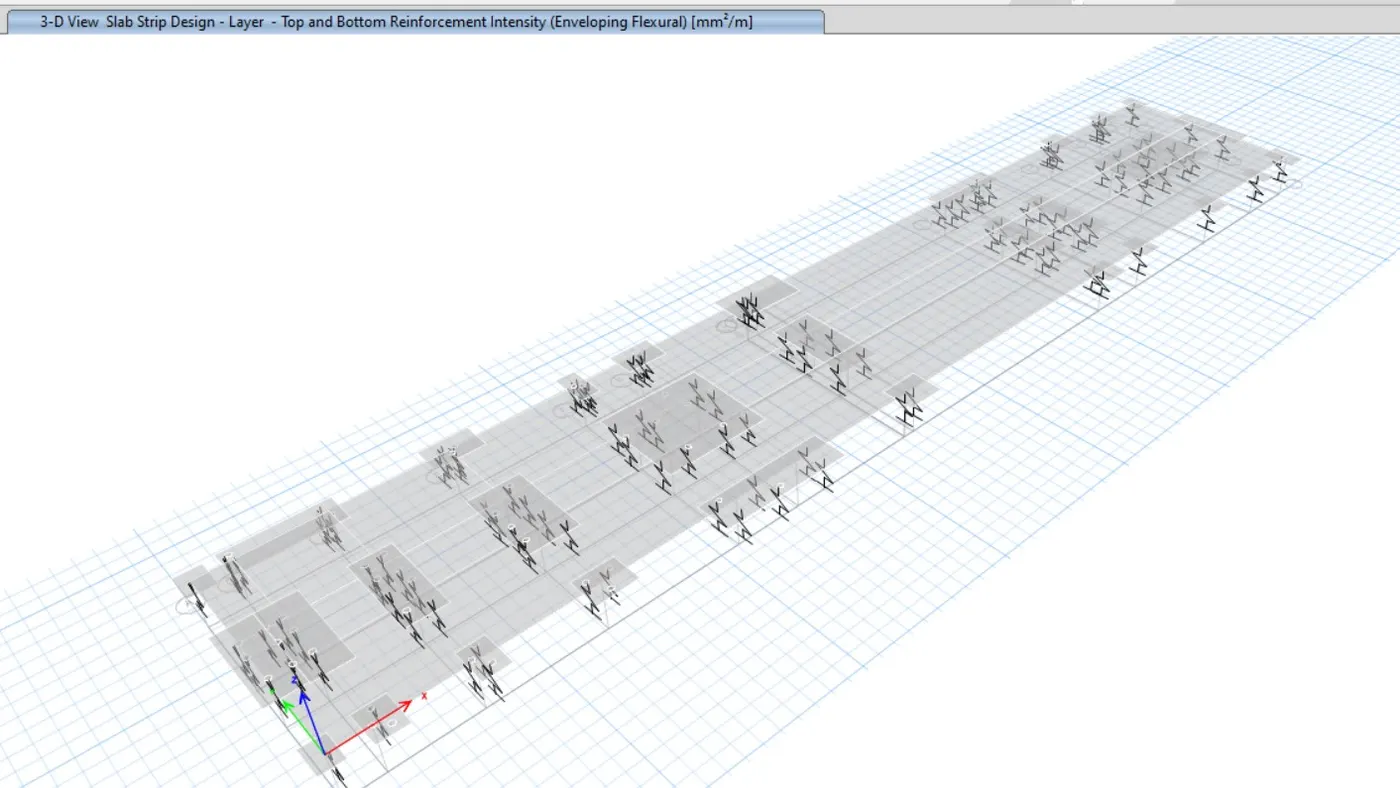
- Now we see that slab strip design results, We can provide the reinforcement at the top and bottom.
Result :
- Analysis and design of high rise buildings using ETABS and foundation design using SAFE for seismic loads are completed using the relevant codes of practice and the outputs are attached.