Project 2_Design & Analysis of a Hostel building at Guwahati, Assam
Project 2_Design & Analysis of a Hostel building at Guwahati, Assam
AIM: To model, analyse, design and to prepare the construction drawings of G+3 RCC building in Guwahati, Assam In this project, to experience the entire design process from modelling, analysis, design, and preparation of construction drawings. The architectural drawings of a G+3 RCC building is provided
IS CODE REFERED:
IS 875 part 1
IS 875 part 2
IS 13920
IS 1893
IS 2911 part 2
IS 456
SP 34
In this project, participants will get to experience the entire design process from modelling, analysis, design, and preparation of construction drawings. The architectural drawings of a G+3 RCC building is provided. The following information on the building is to be used:
- Location – Guwahati, Assam
- Function – Hostel block in an academic institute
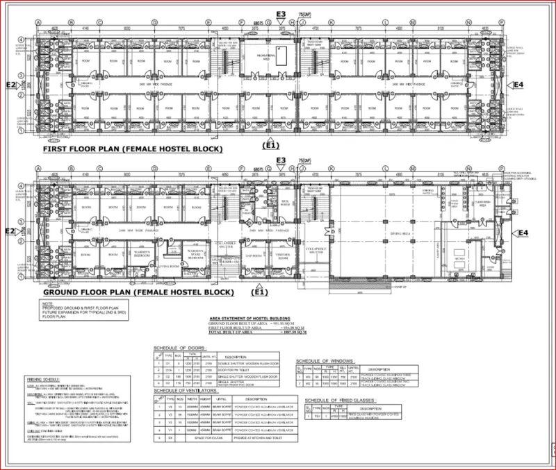
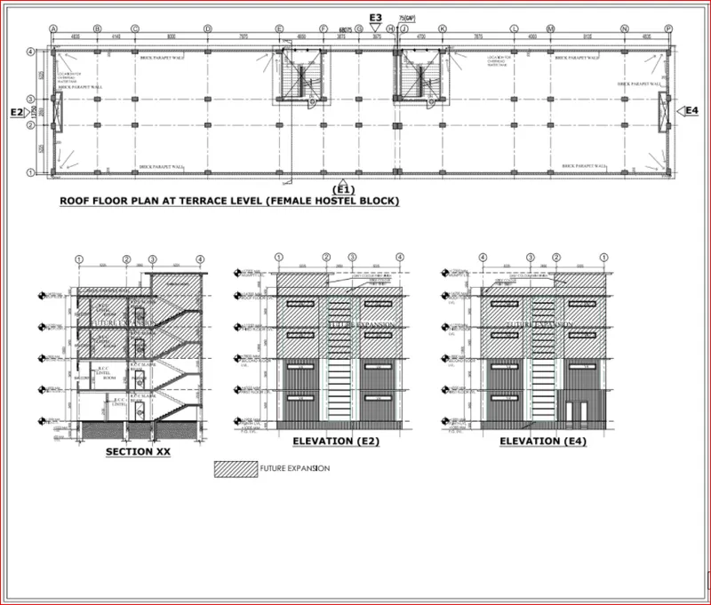
INTRODUCTIONS:
- In this project we are carrying out the design analysis of a G+3 building situated in Guwahati, Assam using ETABS software and then foundation design is carried out using SAFE software.
- ETABS is an engineering software product that caters to multi strorey building analysis and design.
- SAFE represents the state of art in three dimensional finfite element technologies for structural engineering.This software is used to design foundation of the buildings.
PROCEDURE:
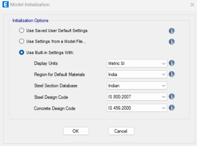
- First Open ETABS software, select new model and setup the model initialization as given below
- After that to edit the grid selection then edit the story option
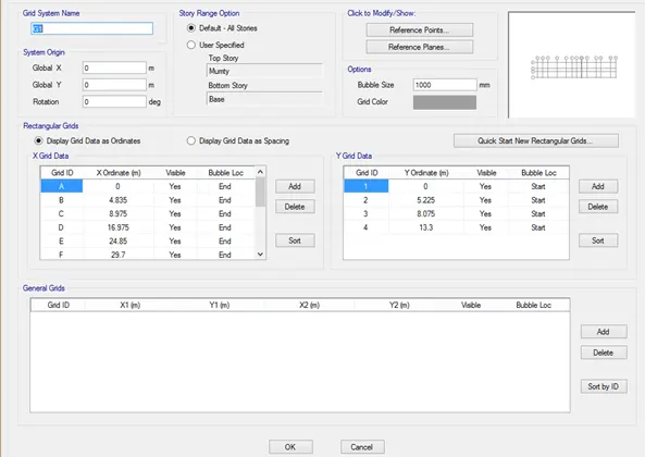
- Now, select Define menu and select Material properties and select Add new material and add M25
- After that select Define menu and select Material properties and select Add new material and add HYSD 500
- After that select Define menu and select Material properties and select Add new material and add HYSD 415
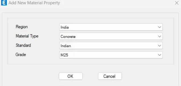
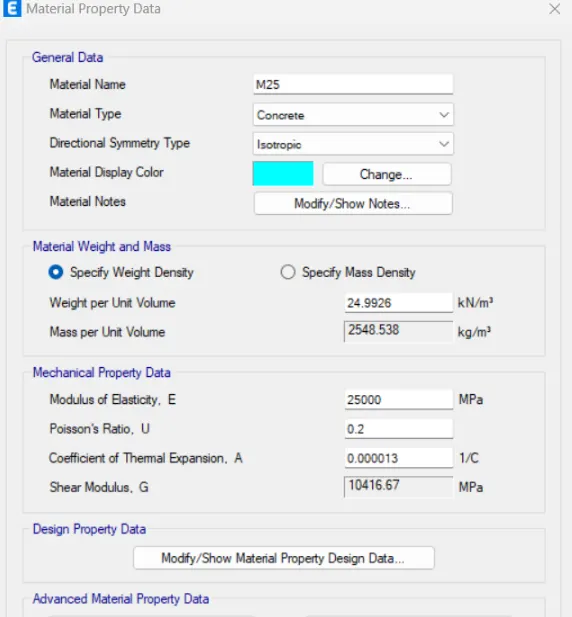
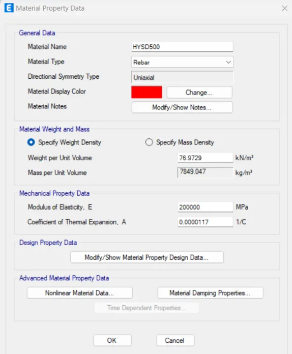
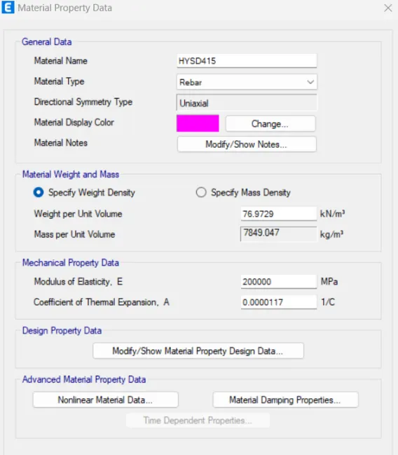
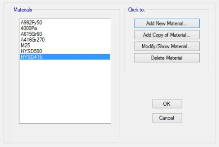
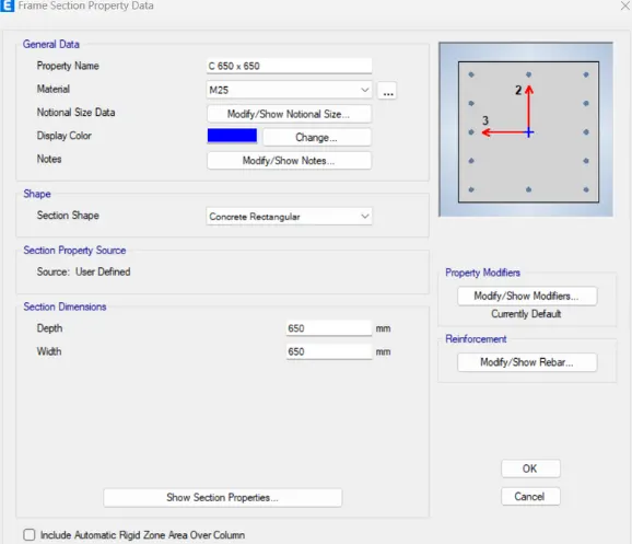
- Now, Select the Define menu and select, section properties and select frame section, select Add new property
- Select Rectangular shape type in concrete and a beam of 230*300 is created and then a column of 650*650 is made.
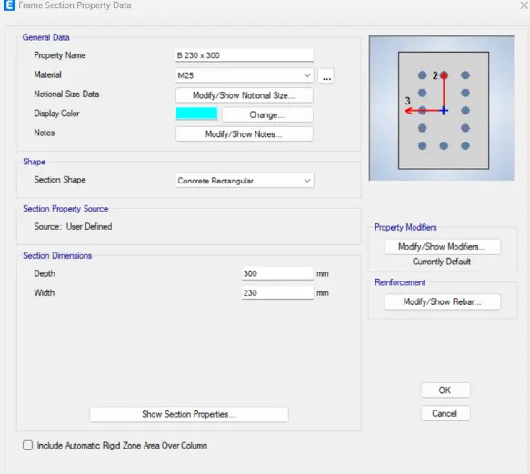
- From the define menu, select section properties, select slab section and select modify/show property
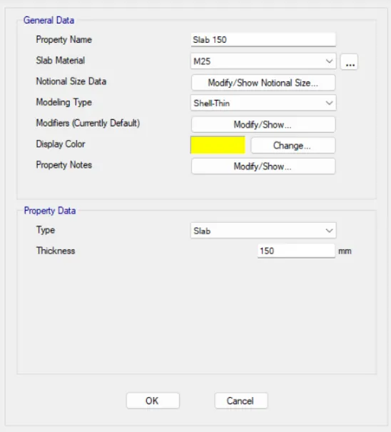
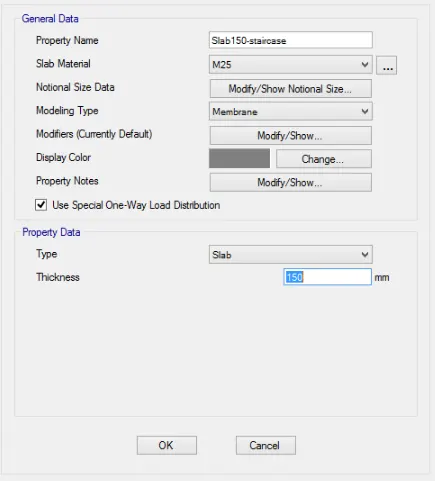
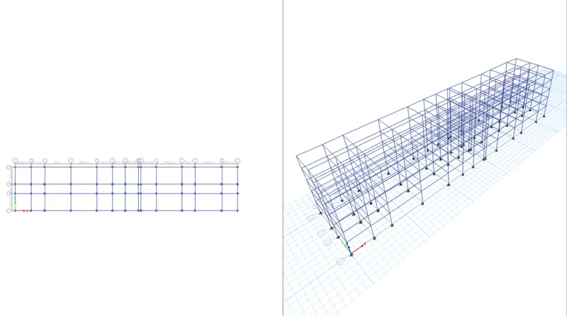
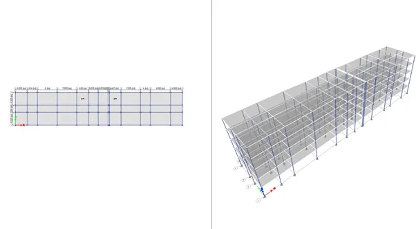
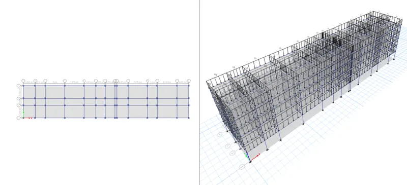
- Now using Qucik draw columns, quick draw beams, quick draw floors/walls,; columns, beams and slabs are drawn
- Along with this, go to the base plan, select all the base joints and from the Assign Menu, select joint, select restraints and select fixed joints and click apply and ok
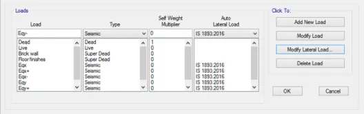
- Now select the Define menu, select load pattern, and enter each load
- From IS 1893:2002, the seismic zone factor for Guwahati is given as 0.36
- Now select the Select menu and select the select option and choose the object type, select beams and close
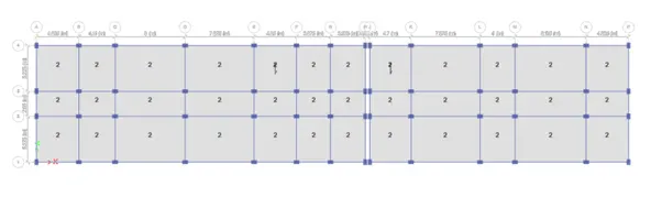
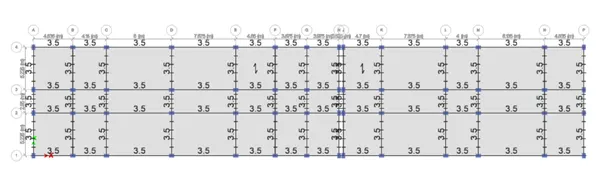
- From the assign option, select frame loads and select distributed load
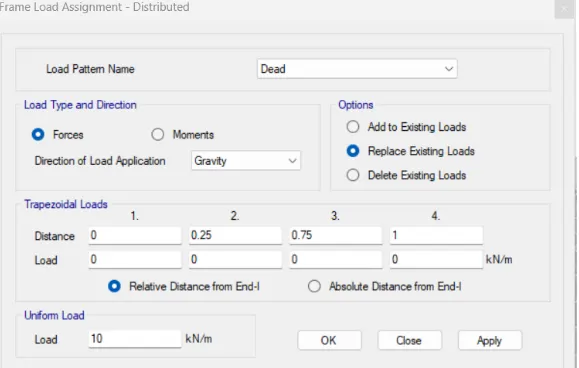
- Now select the Select menu and select the select option and choose the object type, select beams and close
- From the assign option, select shell loads and select uniform load
- Now select the Define menu and select the mass source, and enter the loads
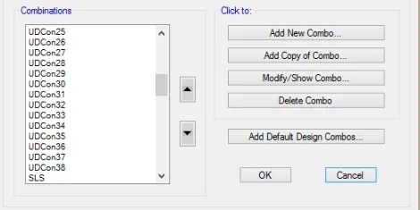
- Select the Define menu and select the load combinations
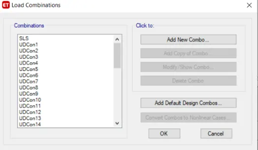
- To select the concrete frame design
- Again select the Select menu and select Object type and select floors,
- Now select the Assign menu and select shell and select diaphragms
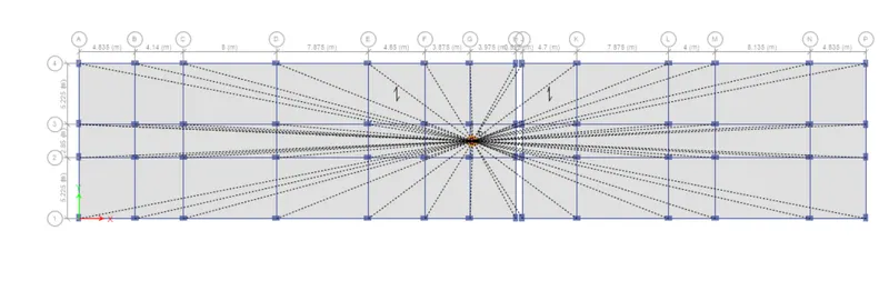
- Now we need to check the model
- Select the show deformed shapes and by entering each load case, deflection corresponding to that load will be visible
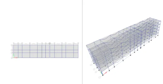
- Now select the Display Design info and select longitudinal reinforcing in the design output and click ok
- We provide 8-14mm dia at the top and bottom, and 5- 16mm dia at the supports for the continuous beam
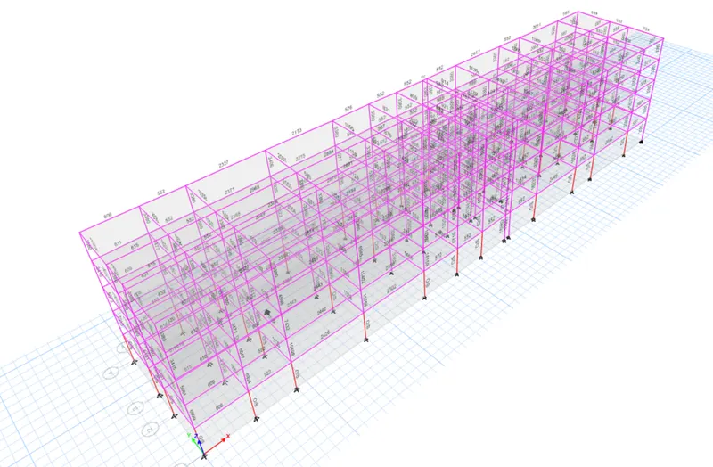
- Now select the Display Design info and select shear reinforcing in the design output and click ok
- We provide 16-16mm dia bars and stirruos of 10mm at 100mm spacing
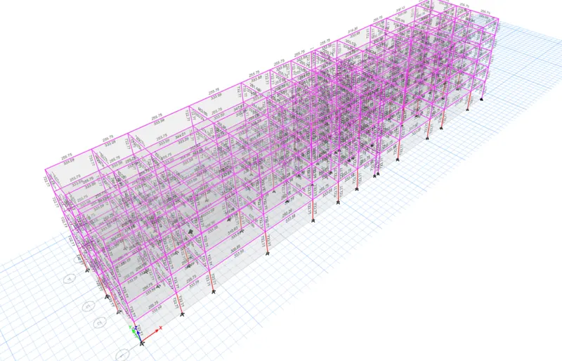
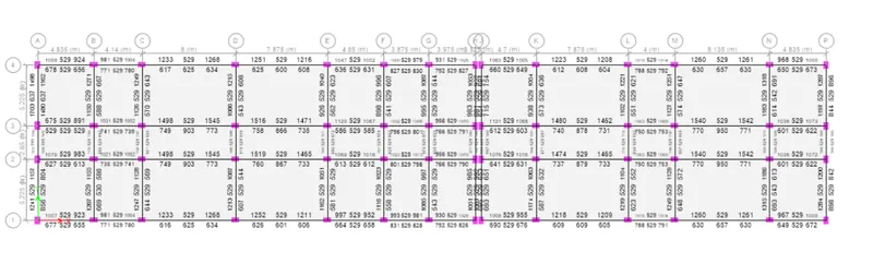
- Now select the plan view and select the base only
- Now export thr base floor loads and loads from above to the SAFE
- Now open the SAFE software and select the exported F2K file by importing it
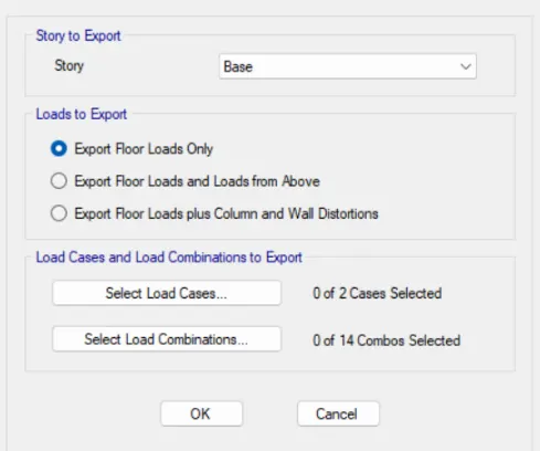
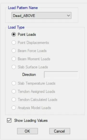
- Now from the display menu, select Show loads and select Dead-ABOVE , thus the load will be visible, and
- similarily for Live -ABOVE
- Now from the Define option, select Materials , Add new materials and add material type.
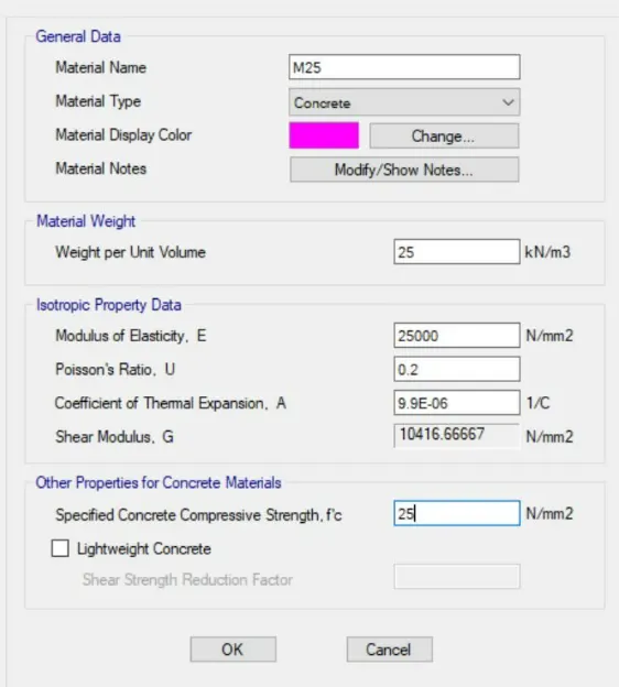
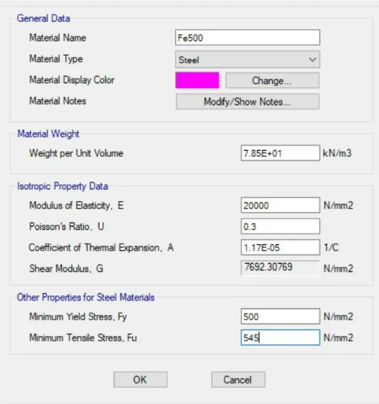
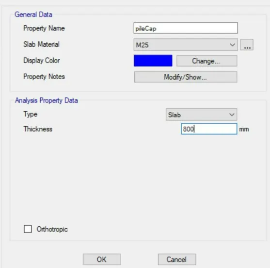
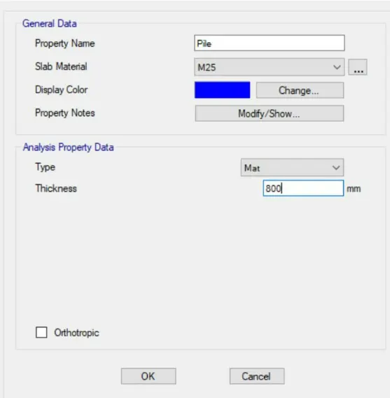
- Now we assign the pile caps, piles and columns accordingly,
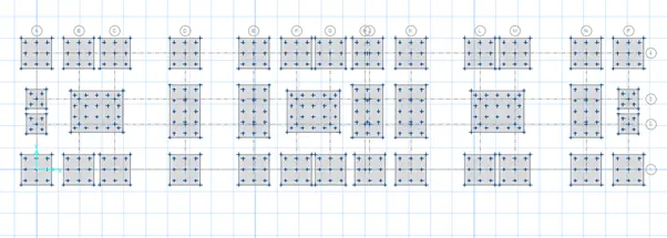
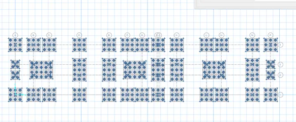
- Now select the Assign menu and select Support Data, from that select soil properties and we enter the subgrade modulus,
- Select the points and Select the assign menu and select the support data and select point springs, in that new tab, we provided E= 5000 sqrt fck = 25000 ; A = area of the pile = 196349.54, and L = 10000mm, Spring constant,K = 490.87KN/mm
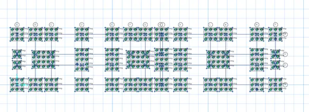
- Now again select the Assign menu and select Load data and select Point loads and add the gravity load and enter the punching shear
- Now right click on the pile cap and in the new tab check the rebar material, similarily for all pile caps
- Now we have to do the run analysis
- Now from the Display menu, select the Show Punching Shear Design,
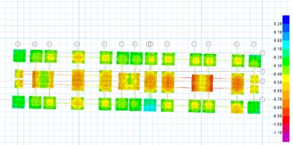
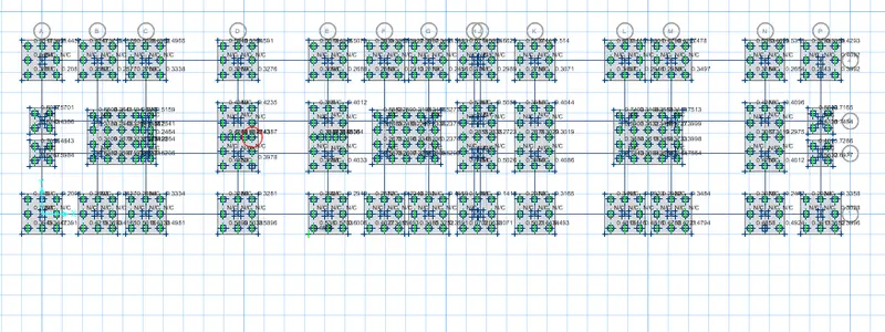
- We got all the values less than 1, so the design is ok,
RESULT :
FINALLY, succeesfully designed and analyzed the model in Etabs and safe.