Project 2_Design & Analysis of a Hostel building at Guwahati, Assam
PROJECT-2:
Design & Analysis of a Hostel building at Guwahati, Assam.
AIM:
To Design & Analysis a Hostel building at Guwahati, Assam.
INTRODUCTION:
ETABS software is a computer program used by engineers and architects to design and analyze structural systems. ETABS is a three-dimensional finite element analysis and design program that can be used to analyze and design buildings, bridges, and other structural systems.
ETABS software is a powerful tool that can be used to design and analyze structural systems. The software can be used to design buildings, bridges, and other structural systems. The software can also be used to analyze the behavior of structural systems under various loading conditions.
The ETABS software can be used to perform a variety of analyses, including linear static analysis, nonlinear static analysis, dynamic analysis, and response spectrum analysis. The software can also be used to generate reports and graphs that show the results of the analyses.
The ETABS software is a valuable tool for engineers and architects. The software can be used to design and analyze structural systems quickly and easily. The software is also easy to use, which makes it a valuable tool for anyone who wants to design and analyze structural systems.
QUESTION:
In this project, participants will get to experience the entire design process from modelling, analysis, design, and preparation of construction drawings. The architectural drawings of a G+3 RCC building is provided. The following information on the building is to be used:
- Location – Guwahati, Assam
- Function – Hostel block in an academic institute
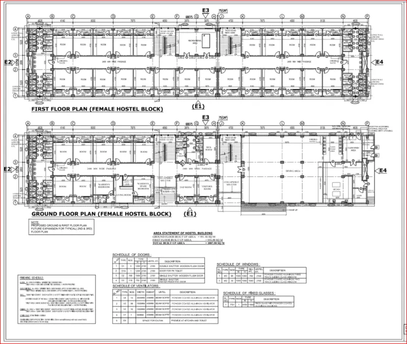
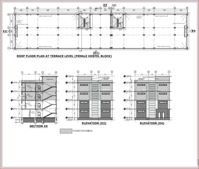
The walls will be made of AAC blocks. Other loadings are to be calculated as per the architectural drawings.
The buildings rests on type 3 soil. Piles of length 10 meters and 500 mm diameter with a load-carrying capacity of 280 KN is to be used.
The ground floor level will be at a height of 2 meters above the existing site level to avoid floodwater enter the building.
M25 grade of concrete with Fe500 for longitudinal reinforcement and Fe 415 for shear reinforcement is to be used.
The following design IS codes will be required for reference:
- IS 875 part 1
- IS 875 part 2
- IS 13920
- IS 1893
- IS 2911 part 2
- IS 456
- SP 34
Objectives of the Project:
- To calculate and assume necessary data from the given architectural and site information
- To model, analyse and design the frame structure using ETABS software
- To model, analyse and design the foundations using SAFE software
- To produce structural Typical floor plans & Typical Rebar drawings
PROCEDURE:
Data required for ETABS analysis:
- Pinned Support, Base + 5 Story (Plinth to Roof) + 1 Mumty
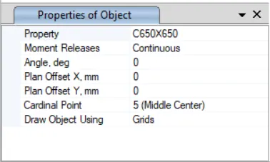
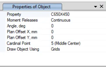
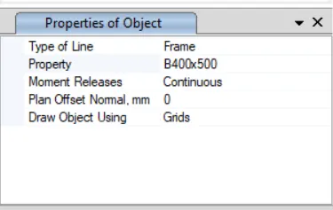
- Column 450mm x 650mm, Beam 400mm x 500mm, Slab 150mm thick, No shear wall necessary
- Floor live load 2 kN/m2,Terrace live load 1 kN/m2, Floor finish + Ceiling finish 1 kN/m2,Partition wall load 3.5 kN/m and Balcony wall load 1 KN/m.
- Guwahati seismic Zone-V
ETABS DESIGNING:
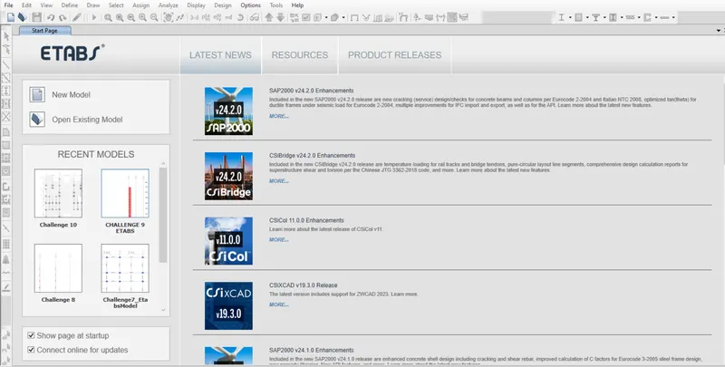
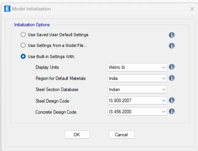
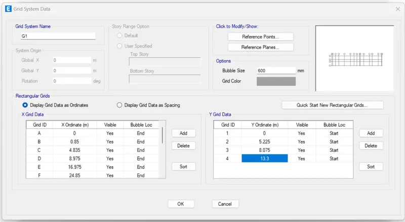
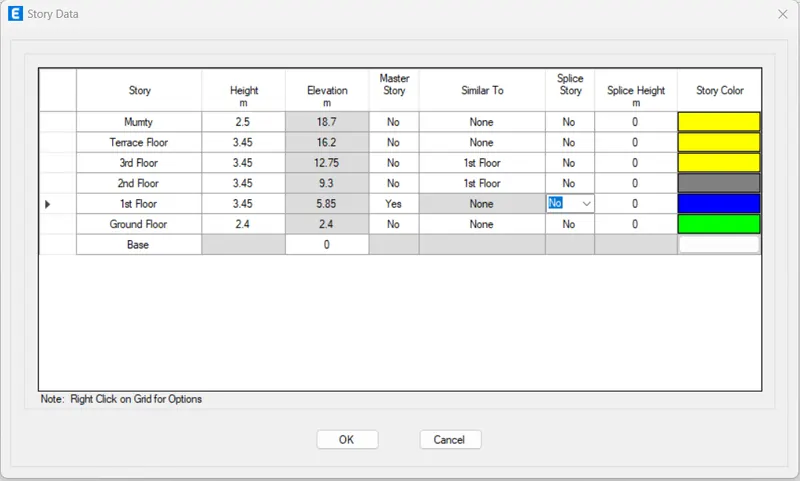
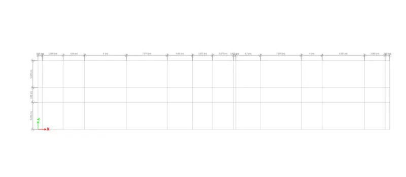
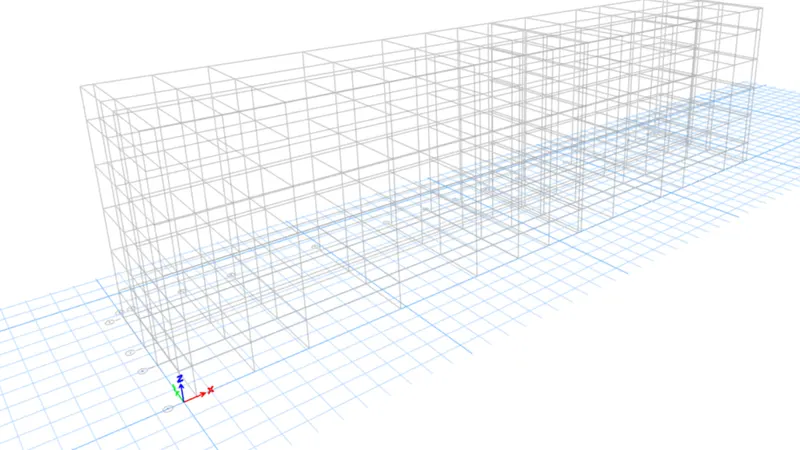
1. Open the ETABS software and click new model to set the required grids and storeys.
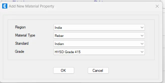
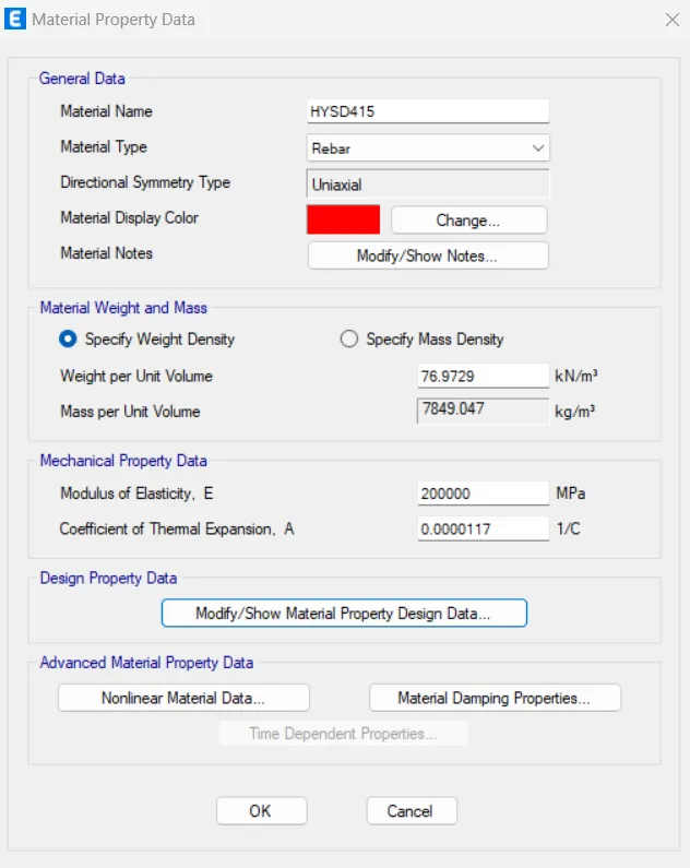
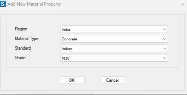
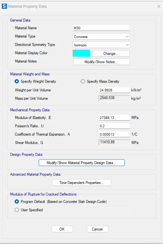
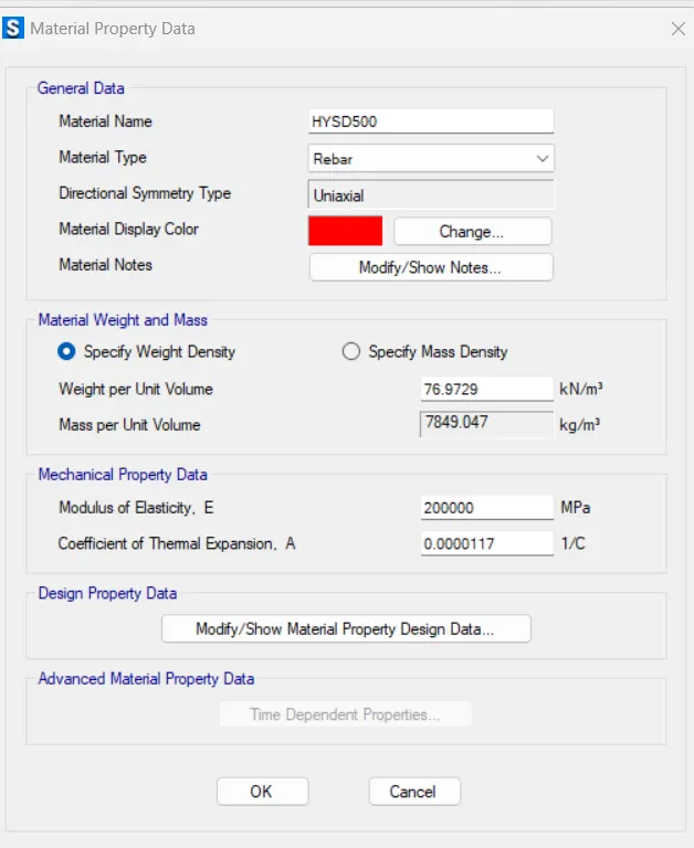
2. Now we have to define the material properties.
Concrete(M30):
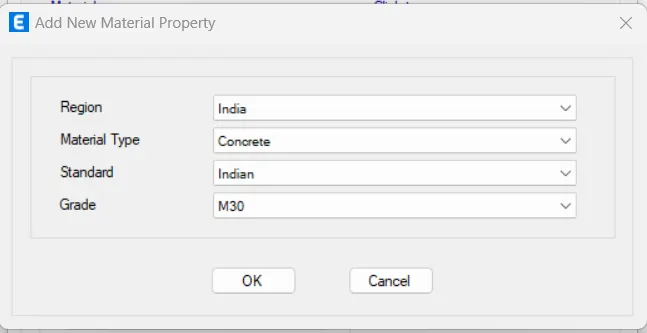
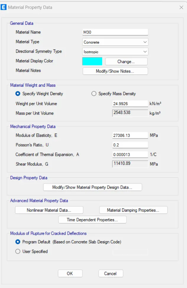
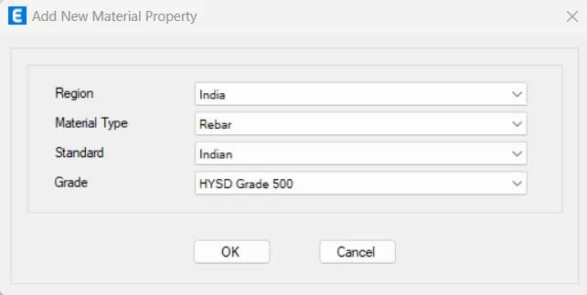
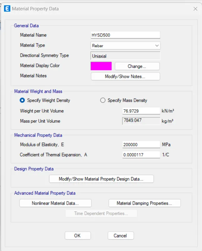
Rebar (Fe 500 for Longitudinal and Fe 500 for Shear reinforcement):
3. After completing Material properties we have to define the section properties.
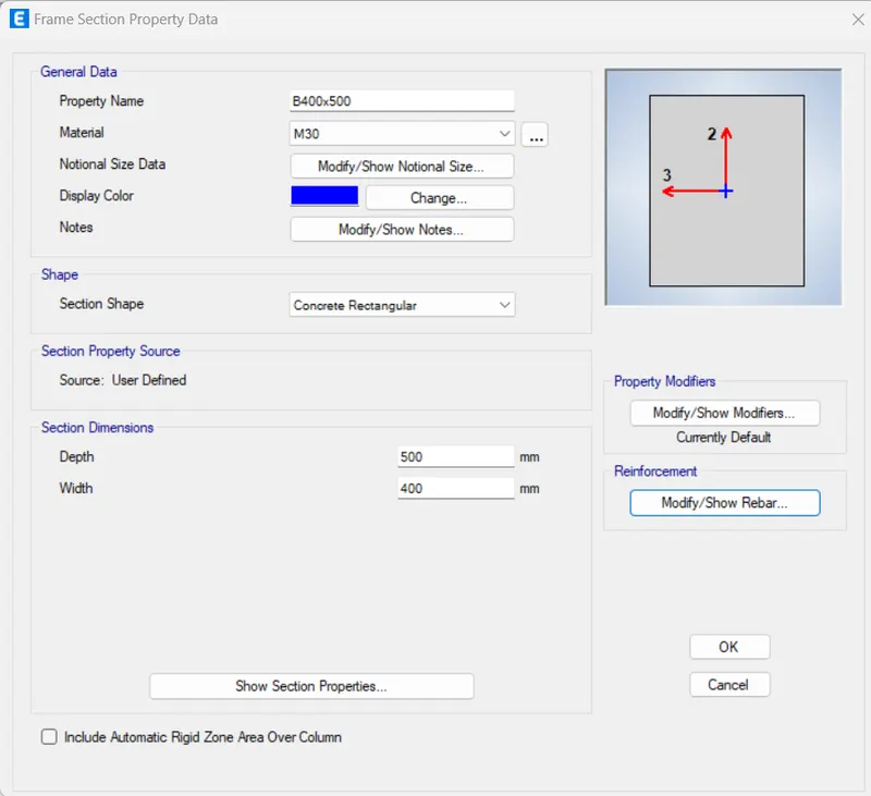
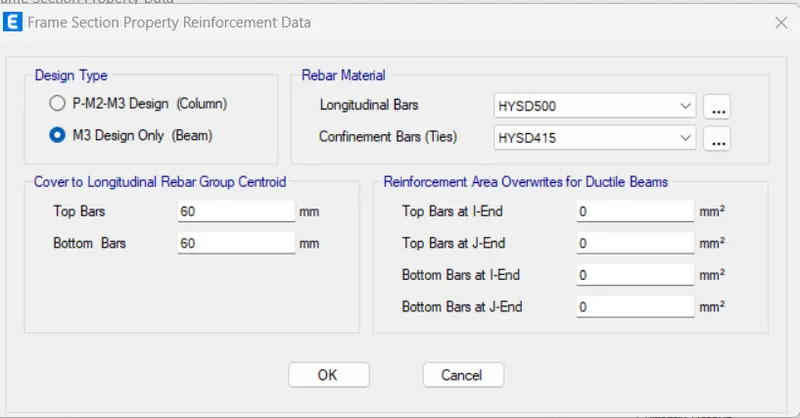
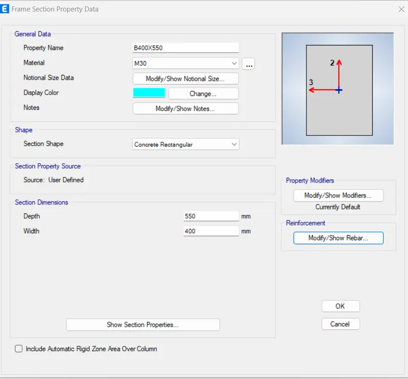
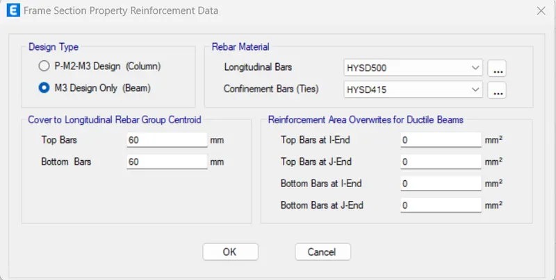
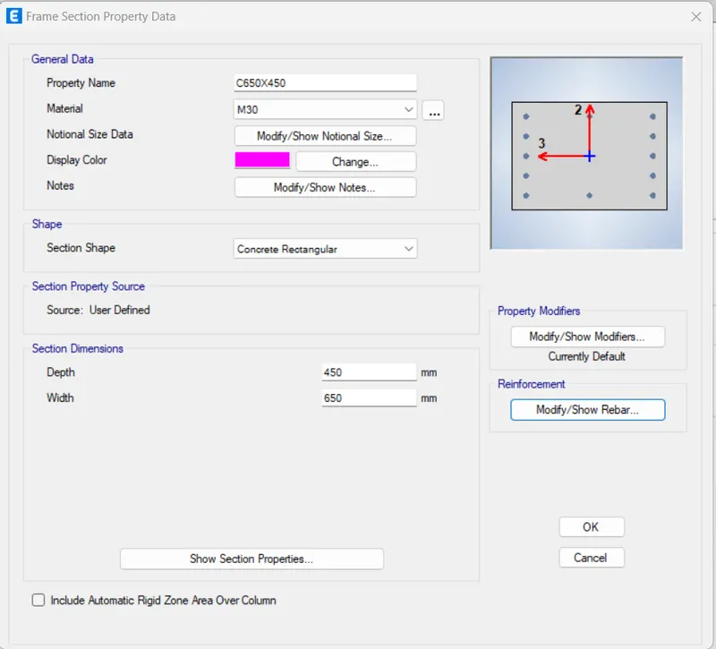
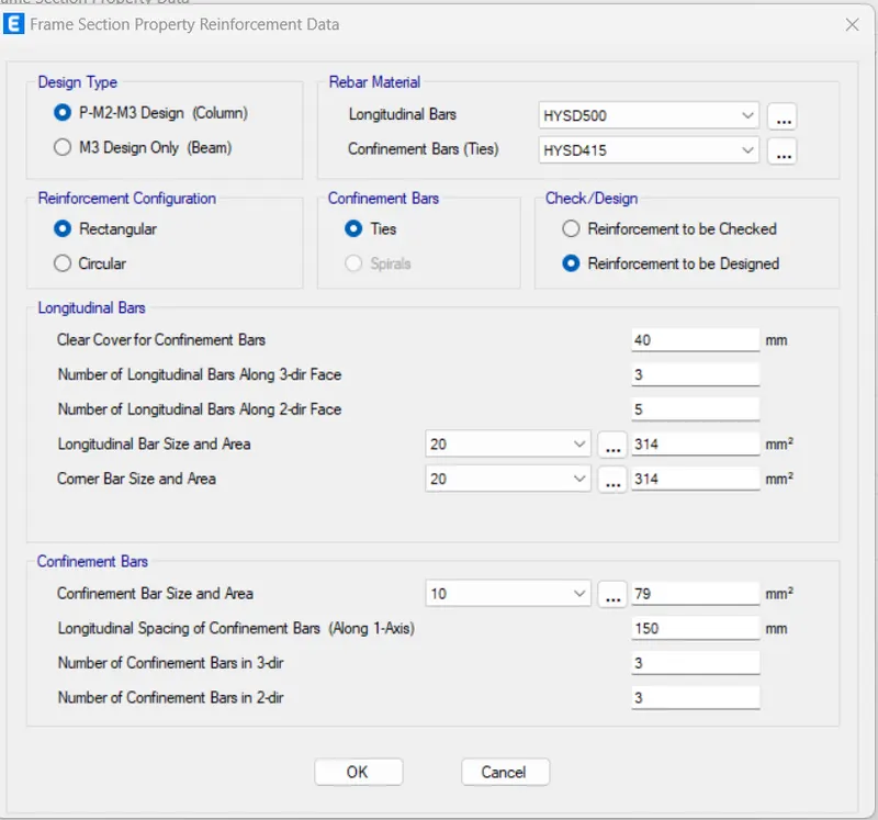
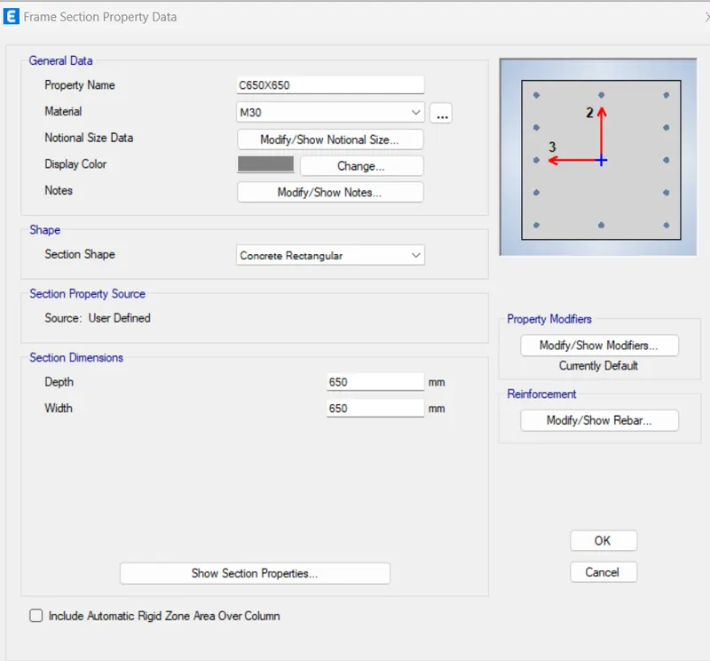
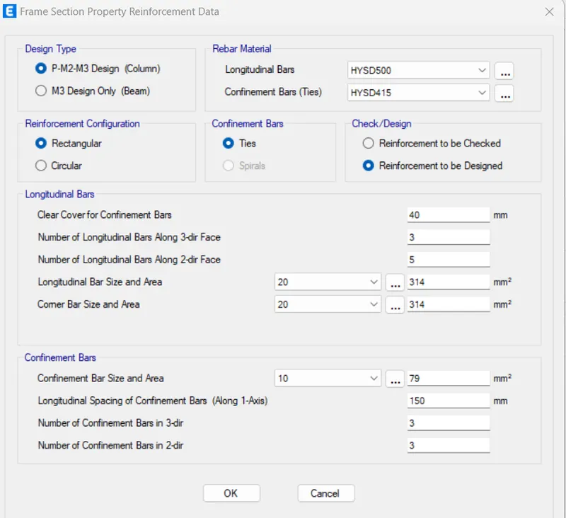
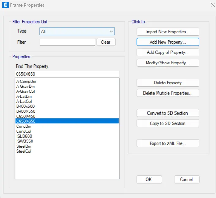
4. After completing the section properties we have to define the frame sections like slab thickness 150mm.
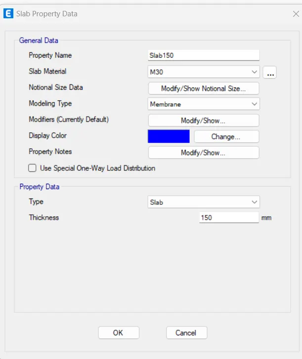
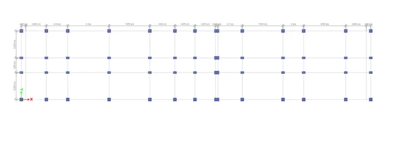
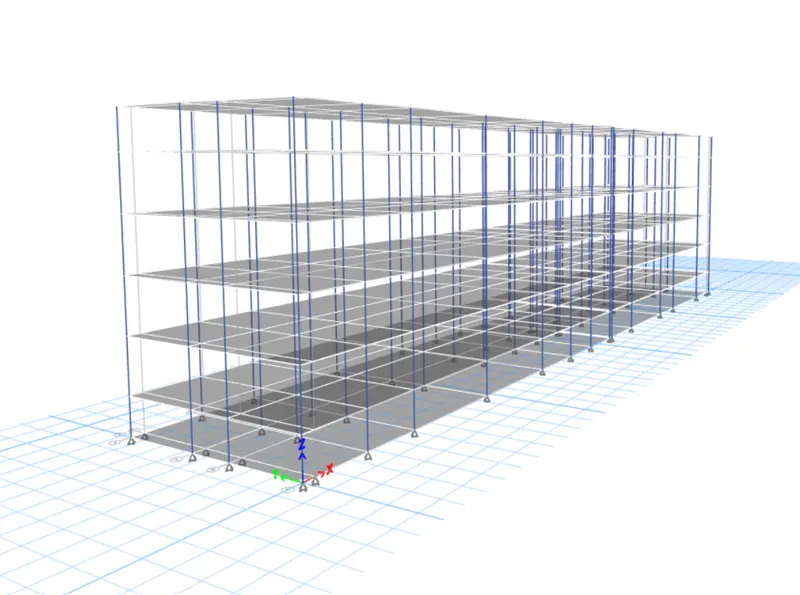
5. After defining the materials now we need to model component columns. Beams and Slab.
Columns:
Beams:
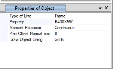
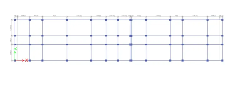
Slab:
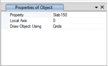
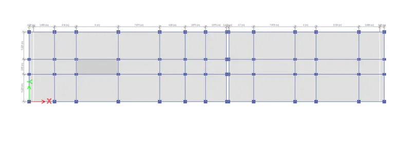
3D:
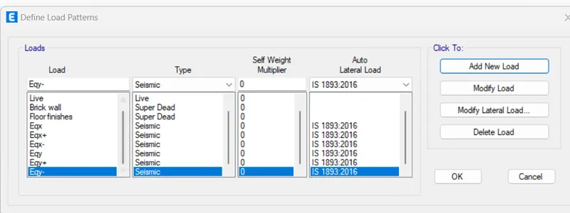
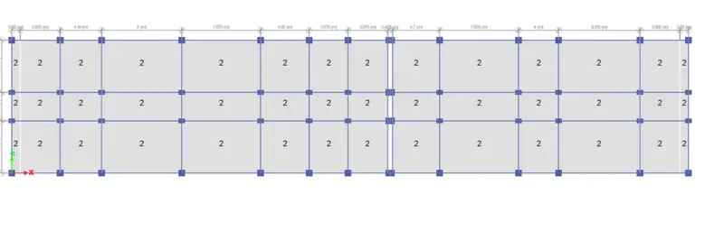
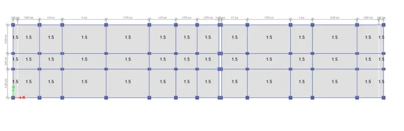
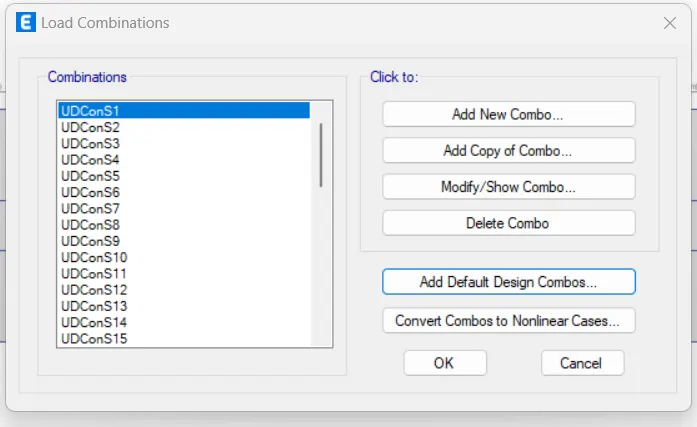
6. After completing the modeling now assign the Loads, load patterns, and load combinations.
- Floor live load 2 kN/m2,
- Terrace live load 1 kN/m2,
- Floor finish + Ceiling finish 1 kN/m2,
- Partition wall load 3.5 kN/m and
- Balcony wall load 1 KN/m.
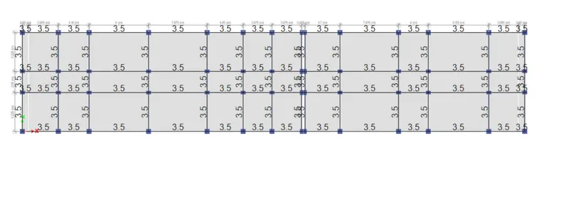
7. Next we have to assign the joints and also define the mass source and response spectrum.
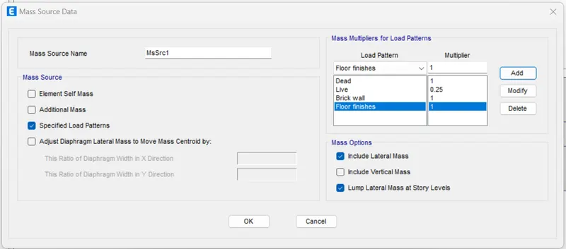
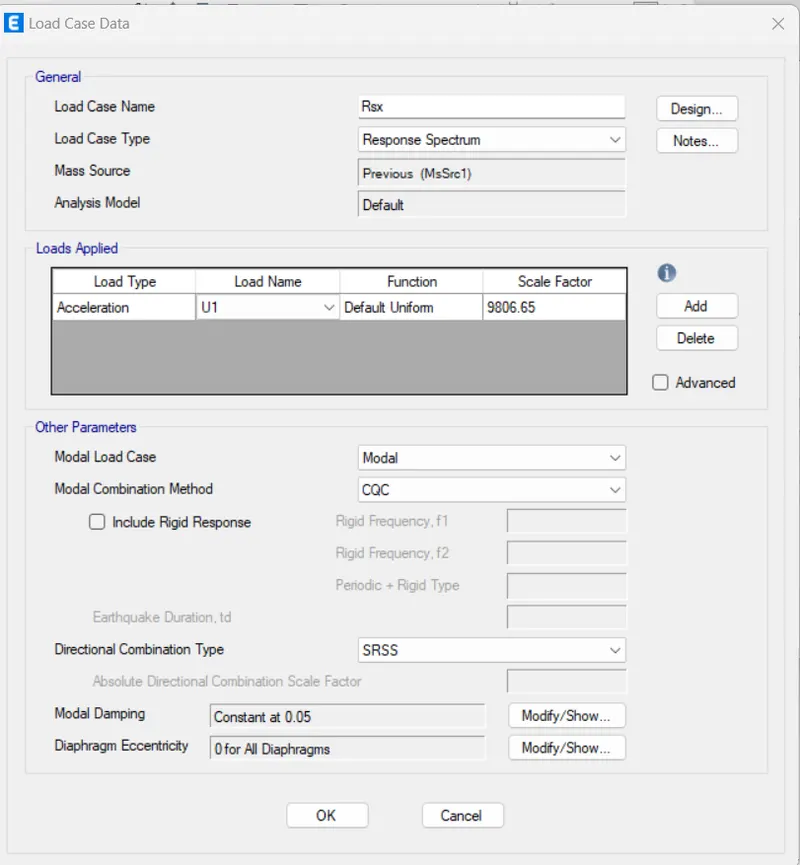
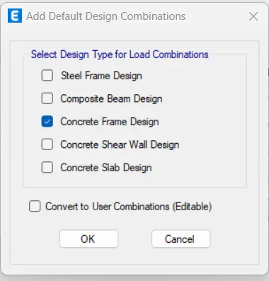
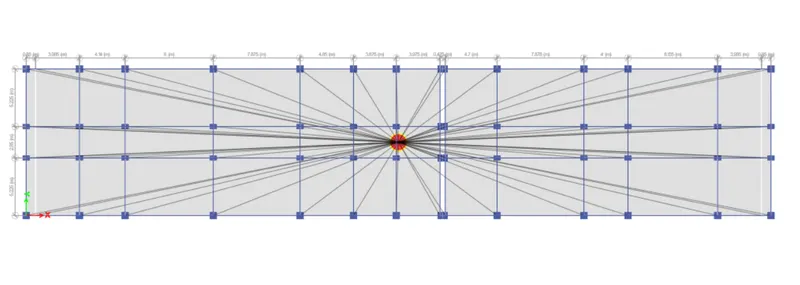
8. After that Assign the Diapharagm to the shell and run the analysis.
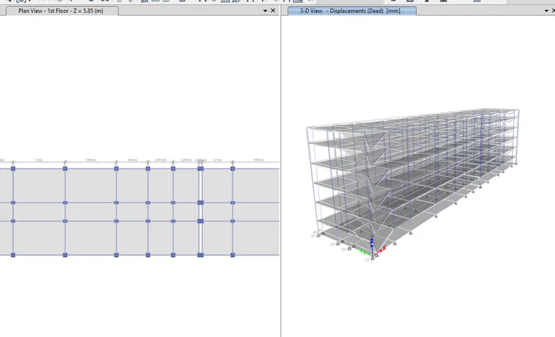
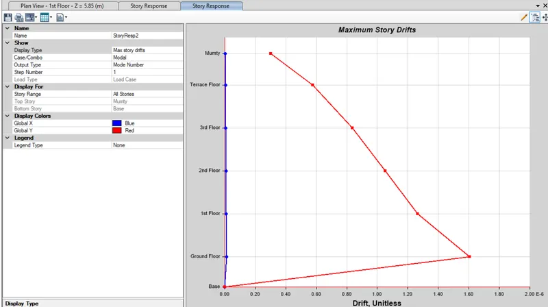
9. After that we need to check the storey drift for Rsx and Rsy with in the limit or not.
10. Next we need to carry the concrete frame design and extract the results for the beam and columns both Fluxure and shear.
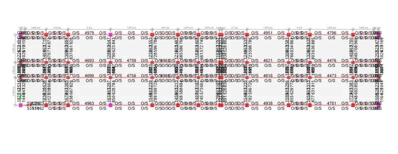
Longitudinal reinforcement:
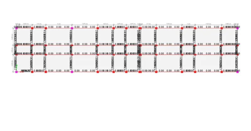
Shear reinforcement:
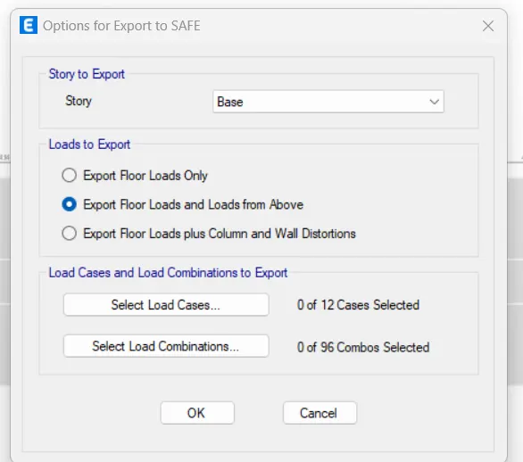
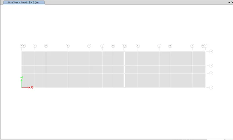
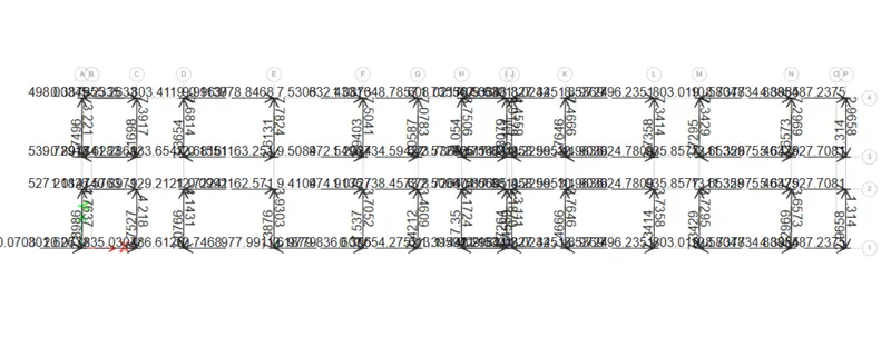
11. Now complete the design part and save it f2k format for footing design and move to the safe software.Now we have to go file to export to story as safe v12.f2k to click base.
12.Next we have to define the material properties.
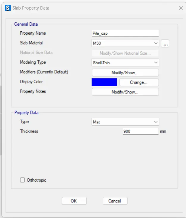
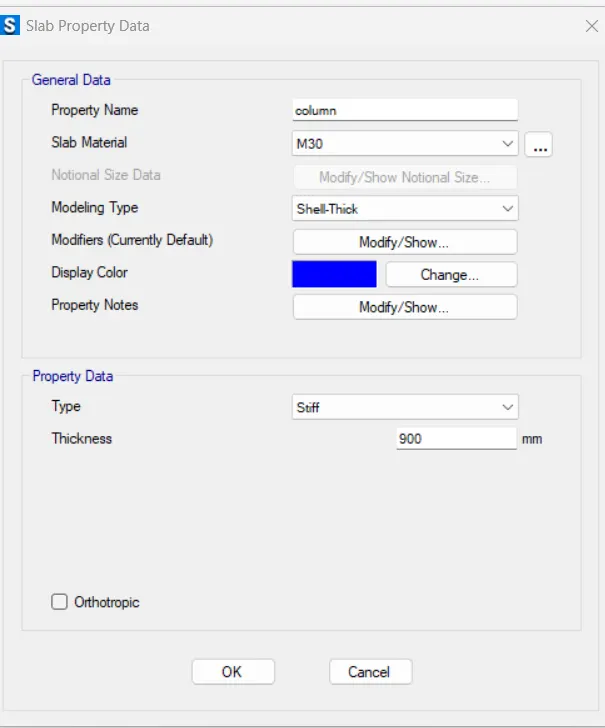
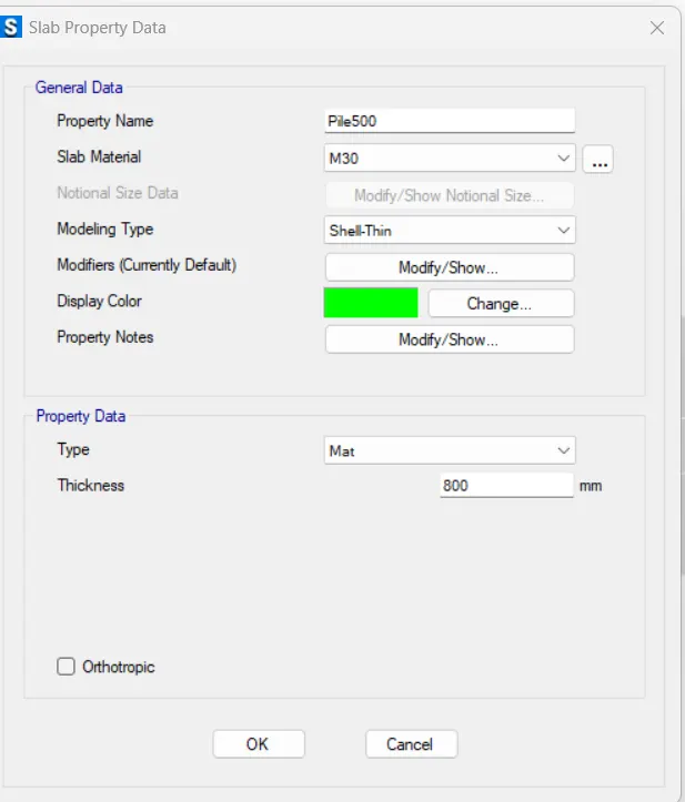
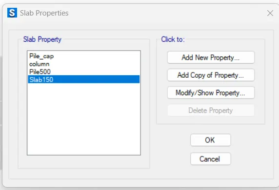
13. After that we have to draw the drop points in the modeling for assigning footings.
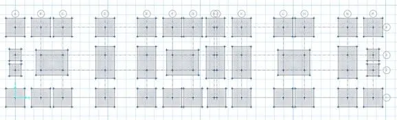
14. After that to developed the piles using drop points.
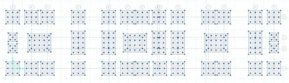
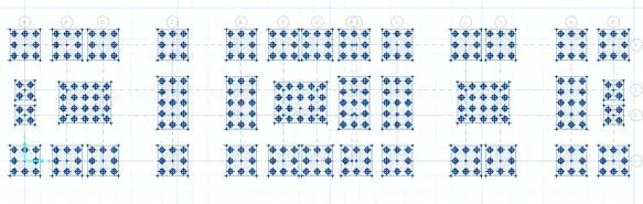
15. After that, we need to assign the pile 500 using drop points.
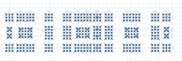
16. After that place the column using Grid intersections.
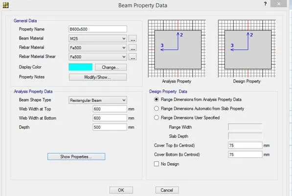
17. Now define the beam for tie beams.
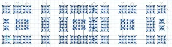
18. After that we need to assign the springs where the piles are located.
19. Now we have to calculate the spring constant,
=AE/L=(196346.5)(25000)/(10000) = 490873 N/mm.
20. Then now assign the spring constant.
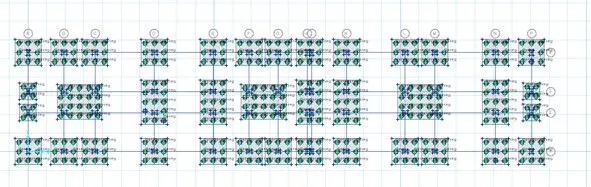
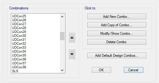
21. Now define the load combinations like service limit and ultimate limit.
22. After that we need to check the design results, all results are with in the limits, hence it is safe.
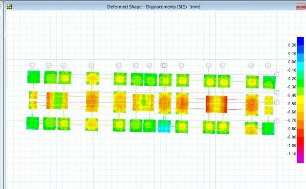
23. Now check the Reactions and punching shear values.
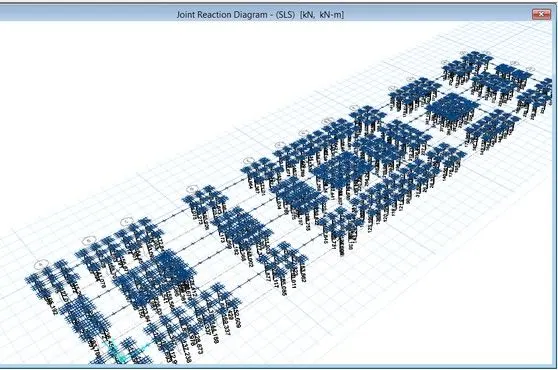
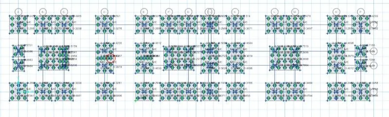
24. Reaction values and punching shear values within the range, Hence it's okay.
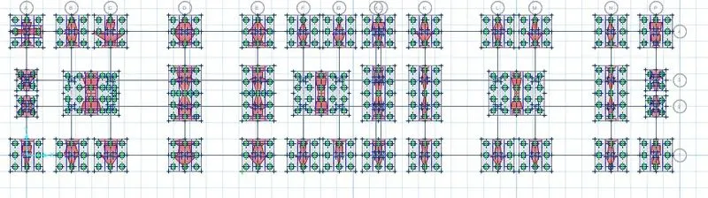
25. After that we have to design the strips along with A and B.
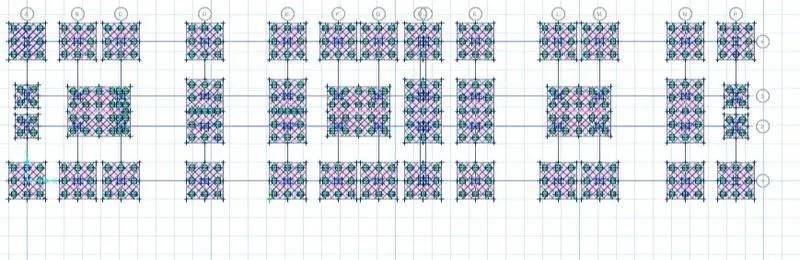
Strip layer A:
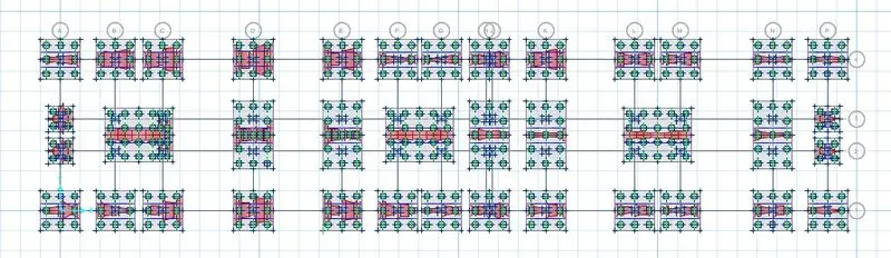
Strip layer B:
26. Hence, the design of the footing is completed.
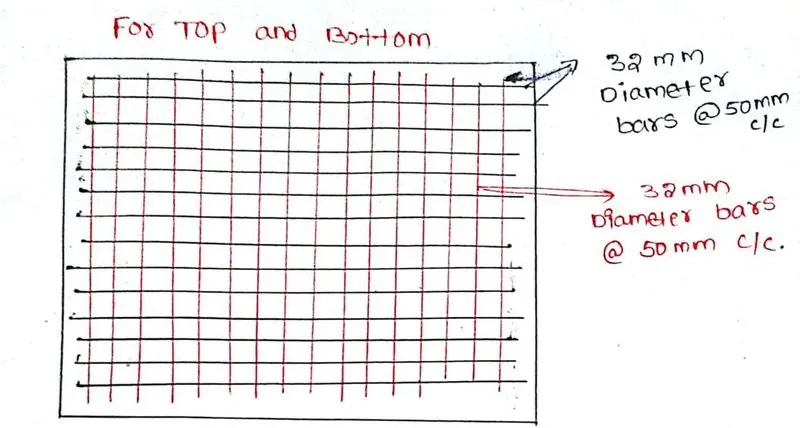
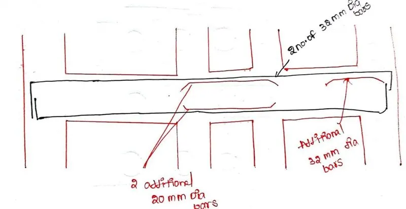
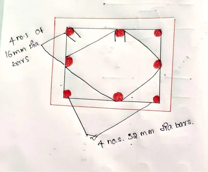
27. The reinforcement details are shown below.
BEAM:
COLUMN:
RESULTS:
- Modeling, Analysis, and design of the G+3 building have been carried out with ETABS Software.
- Foundation design Pile and pile cap is carried out to be SAFE software.
- Reinforcement details associated with modeling have been included.
.....................................................THE END..........................................................................................................