Project 2_Design & Analysis of a Hostel building at Guwahati, Assam
ETABS
Initially,we start with the selection of New Model in the ETABS software.
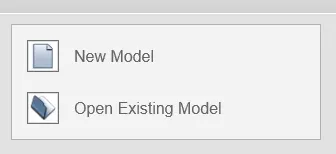
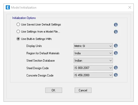
Where we initialize the new model as shown in the Model Initialization Tab.
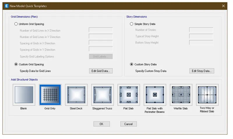
Where we give the required Grid data and the Storey data.
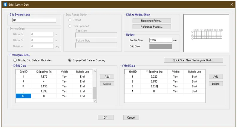
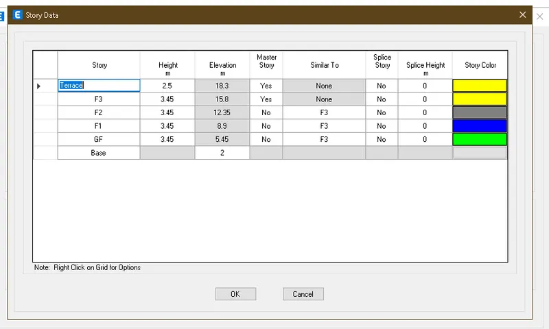
Where the resultant grids are formed.
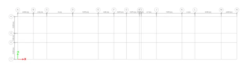
The we continue with the definition of the materials.
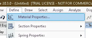
Where we go to Define Tab>Material Properties...
We then add the new materials as required.
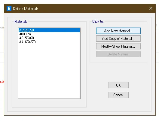
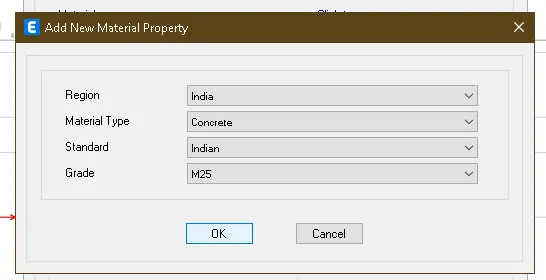
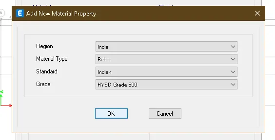
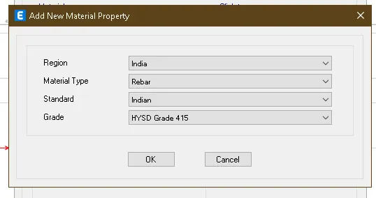
Where we use the M25 grade of concrete and the Fe500 and Fe415 grades of rebars for the longitudinal reinforcement and the tranverse reinforcement respectively.
After the definition of the materials,we go with the definition of the sections.
Where we go to Define Tab>Section Properties>Frame Sections... to define the beam and column sections.
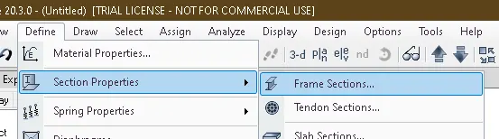
We then add the new sections.
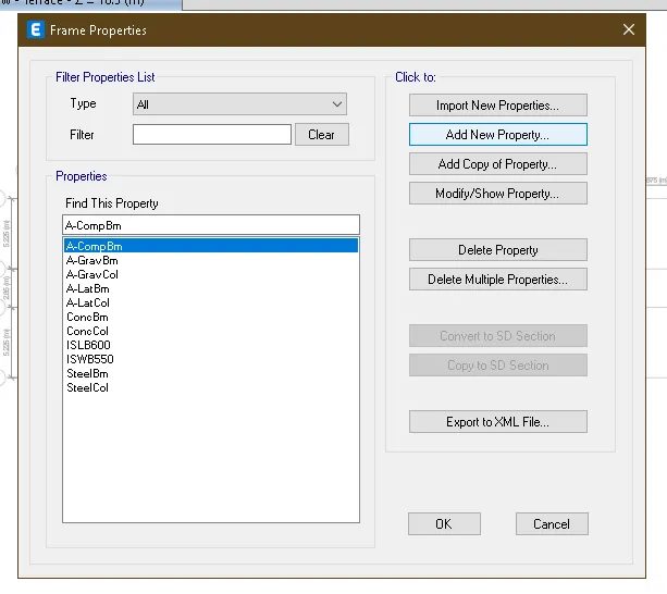
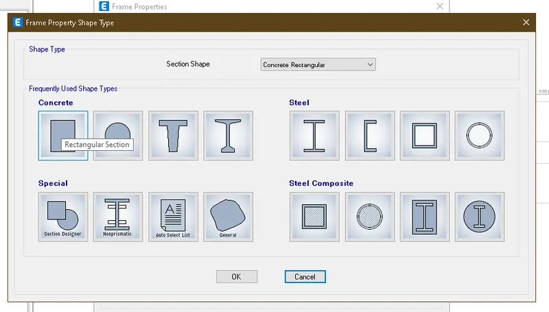
Where the beam and column do have the rectangular shape.
We then give the required information.
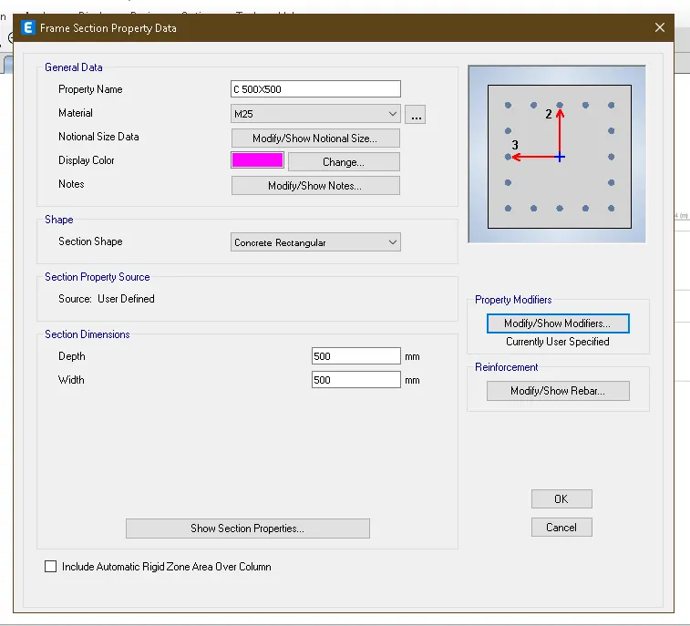
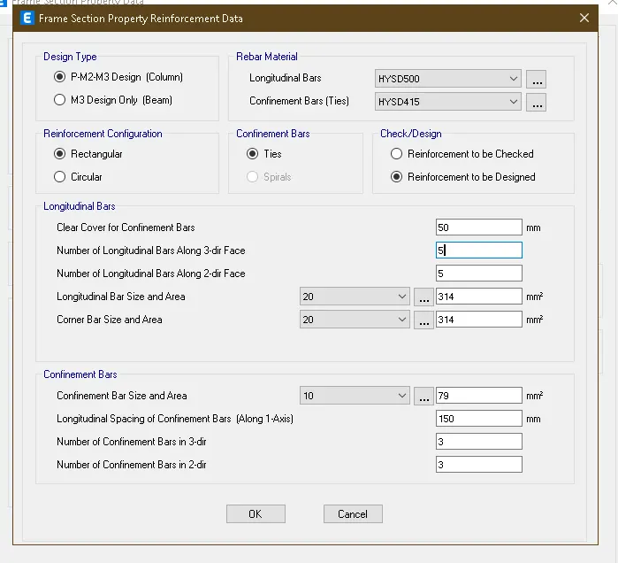
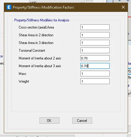
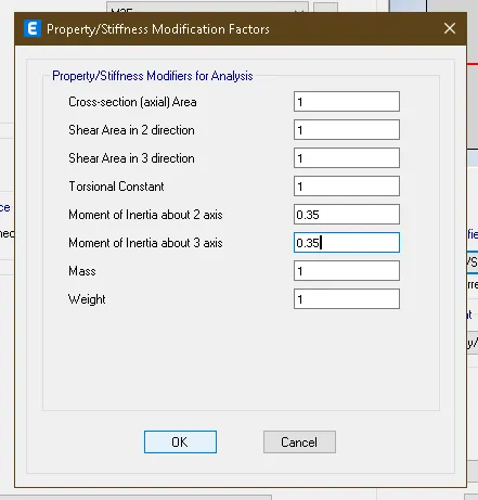
Where we reduce the moment of inertia of the columns to 70% as per the codal provisions.
We do give the details for the beam in the same manner.
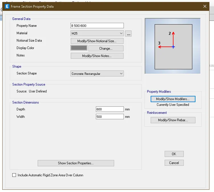
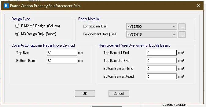
Where we reduce the moment of inertia of a beam to 35% as per the codal provisions.
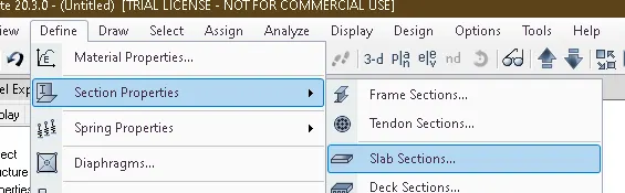
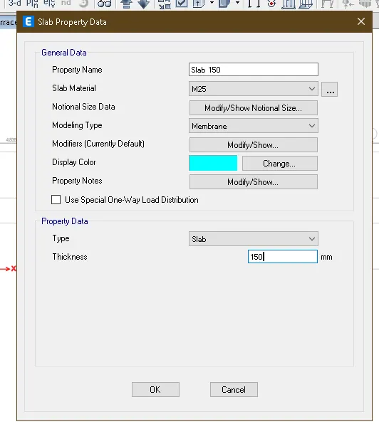
We then go to Define Tab>Section Properties>Slab Sections... to define the slab.
After the definiton of the the require sections,we do draw them.
Where to do this we use the option of Quick Draw Columns for drawing the columns.
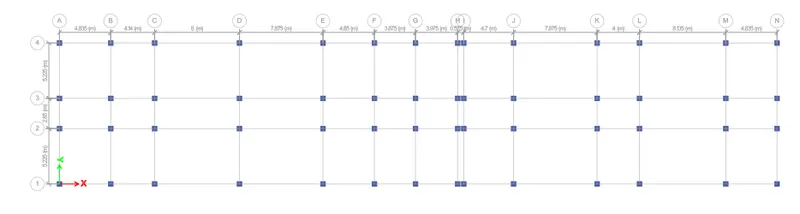
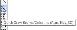
And in the same manner,we use the option of Quick Draw Beams to draw the beams.
Where care is to be taken that we don't provide the beams at the expansion gap.
Where then we provide the slab using the option of Quick Draw Floor.
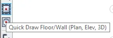
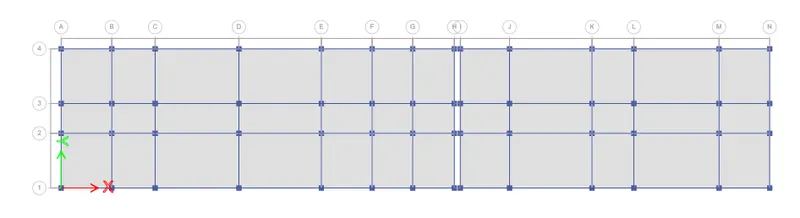
Where care is to be taken that the required are to be added at the required only.
The columns and the beams will be present all over the building but the slabs are not necessary for the base.
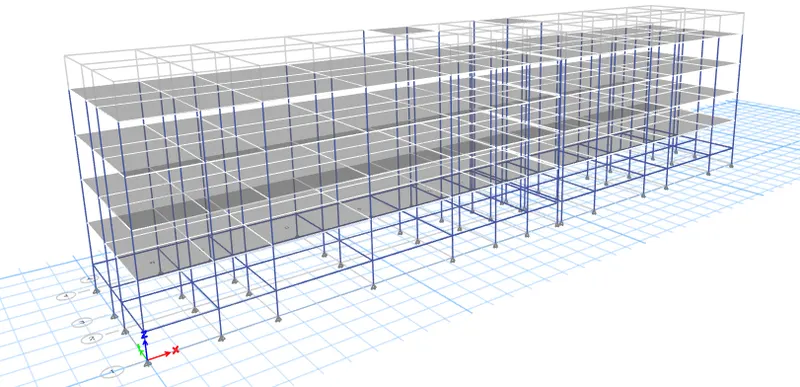
Once the model is formed,we then go with the defintionn of the loads.
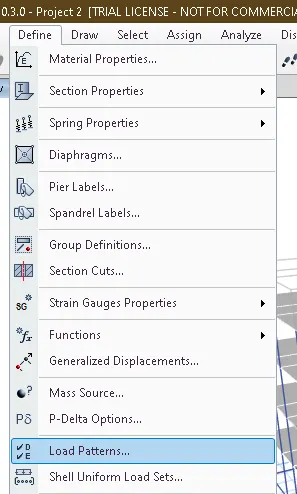
At first we go to the Define Tab>Load Patterns...
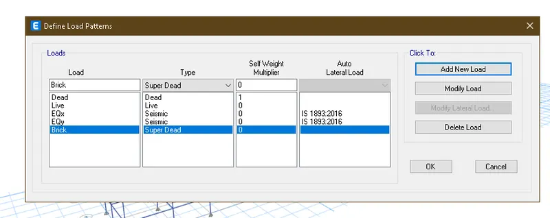
Where we add the required loads,as the building falls in the Zone 5,it is mandatory that the earthquake forces may act where we design the building to resist them too.
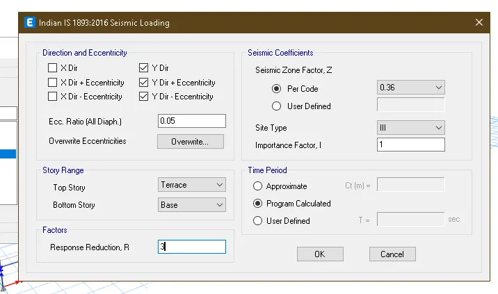
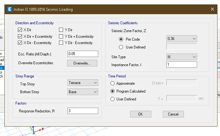
As the building is of normal RCC typer,we use the Response Reduction Factor of 3 and the Zone Factor of 0.36 for the Zone 5 and the Type of the Soil is 3 and the Importance Factor of 1.
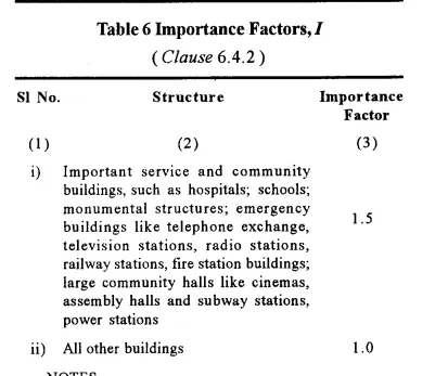
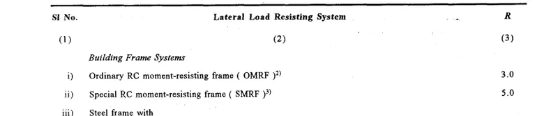
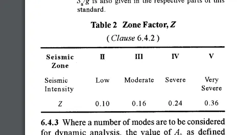
We then define the mass source for the earthquake mass.
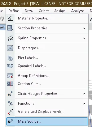
We go to the Define Tab>Mass Source...
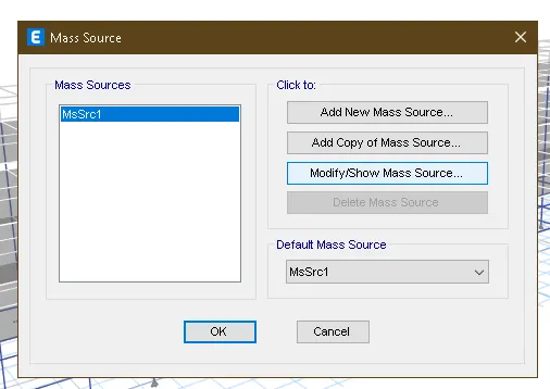
Where we modify the available one.
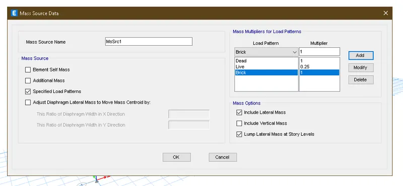
As per the codal provisions we consider only 25% of the live loads during the earthquakes.
We then go to Define Tab>Load Combinations...
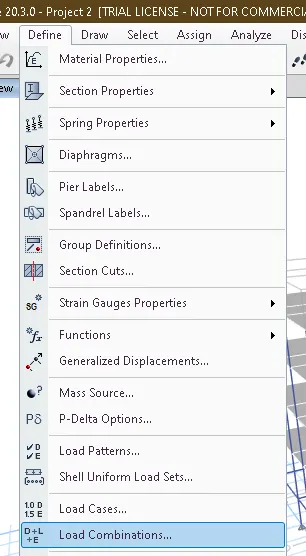
Where don't create anything new but we add the default one.
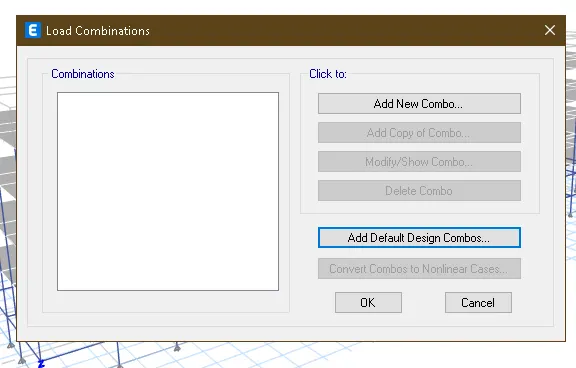
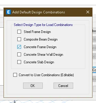
Where we select Concrete Frame Design as we use only the beams and columns.
We then assign the loads to the structure.
Where we go to Select Tab>Select>Object Type...
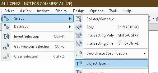
Where we select the required and we assign the loads to them.
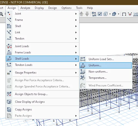
After the selection,we go to Assign Tab>Shell Loads>Uniform... to assign the loads to slab.
And we even go to Assign Tab>Frame Loads>Distributed... to assign the loads to frame.
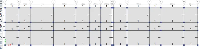
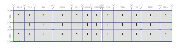
The loads we assign are:
- Floor Live Load=2 KN/sq m
- Terrace Live Load=1 KN/sq m
- Floor Finishing Load=1 KN/sq m
- Partition Wall Load=3.5 KN/m
- Terrace Wall Load=1 KN/m
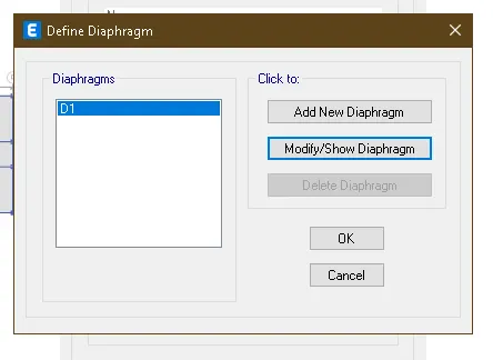
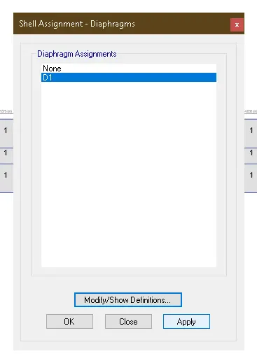
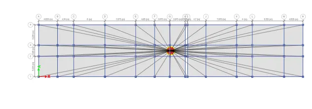
We then assign the Diaphragm,where we go to Assign Tab>Shell>Diaphragms...
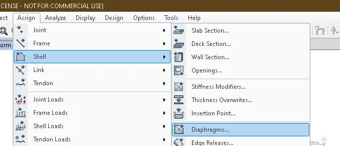
We add the default one.
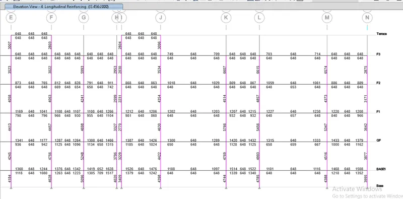
We then go to Concrete Frame Design,to get the longitudinal reinforcement.
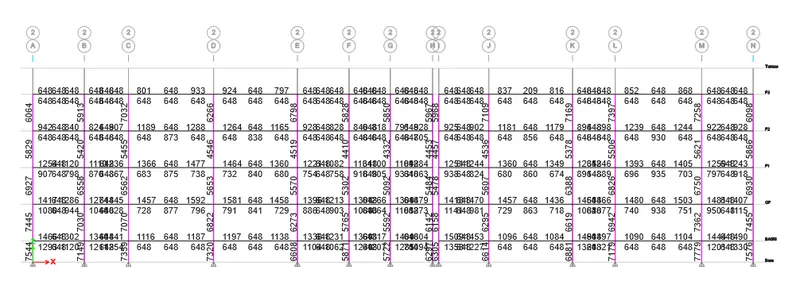
Where design the longitudinal reinforcement for the column with higher reinforcement requirement of 7779 sq mm.
Where we even check the reinforcement for the beam too with the higher reinforcement of 1628 sqmm.
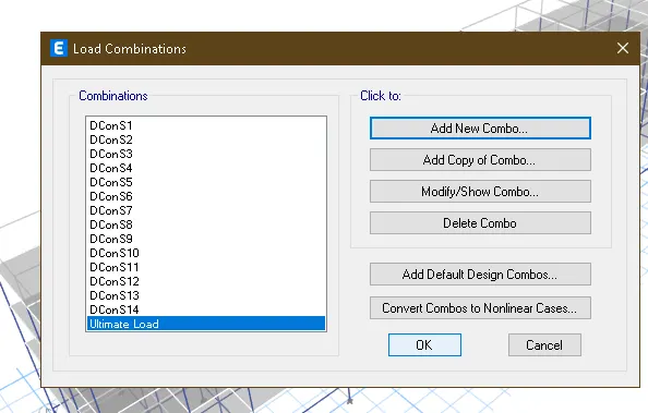
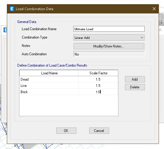
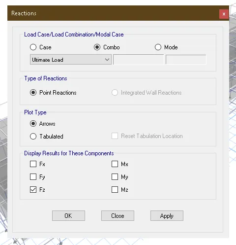
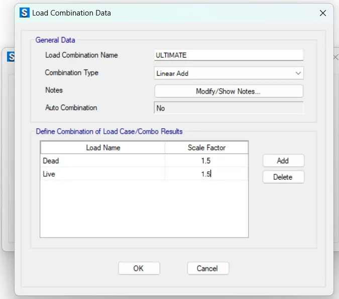
For us to get the base reactions,we add a Ultimate Load combination.
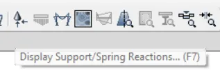
We go to Display Support Reactions...
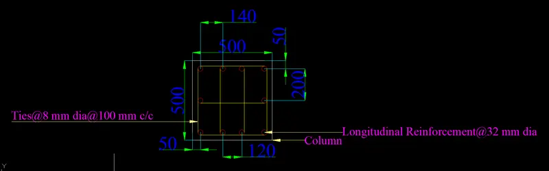
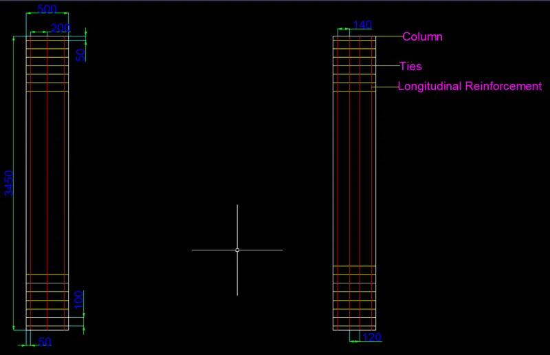
Column Reinforcement
We use 32 mm dia bars as the longitudinal reinforcement.
7779/(3.14X16X16)=9.67=>10 bars
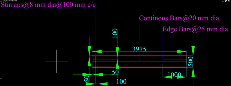
Beam Reinforcement
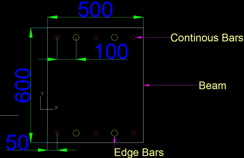
We use the 20 mm dia bars as the continous bars in the longitudinal reinforcement and the 25 mm dia bars as the extra bars at the edge.
For the top reinforcement,
Initially we design the middle reinforcement and then basing upon this we design the edge reinforcement.
652/(3.14X10X10)=2.07=>3 bars@20 mm dia
3X314=942 sq mm>652 sq mm
1628-942=686/(3.14X12.5X12.5)=1.3=>2 bars@25 mm dia
942+(2X490.25)=1923.25 sq mm>1628 sq mm
For the bottom reinforcement,
Initially we design the middle reinforcement and then basing upon this we design the edge reinforcement.
709/(3.14X10X10)=2.25=>3 bars@20 mm dia
3X314=942 sq mm>709 sq mm
1517-942=575/(3.14X12.5X12.5)=1.17=>2 bars@25 mm dia
942+(2X490.25)=1923.25 sq mm>1517 sq mm
So,we have the same no. of bars for the bottom and top.
And we use a cover of 50 mm on both sides and we give a spacing of 100 mm b/w bars.
Shear Reinforcement
We use 8 mm dia bars for the stirrups and ties.
3.14X4X4=50.24 sq mm
For the beams,at edges,5X50.24=251.2 sq mm
251.2X10=2512 sq mm>1527.76 sq mm
For the beams,at middle,3X50.24=150.72 sq mm
150.72X10=1507.2 sq mm>1443.71 sq mm
For the columns,for the major axis,4X50.24=200.96 sq mm
200.96X10=2009.6 sq mm>1612.53 sq mm
For the columns,for the minor axis,3X50.24=150.72 sq mm
150.72X10=1507.2 sq mm>934.70 sq mm
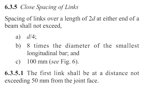
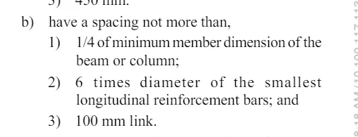
Where we use the spacing of 100 mm c/c for the stirrups and the ties as per the codal provisions.
SAFE
Where we design the Pile Foundation for the Column A1.
The details of the Pile Foundation be,
Column Size=500 mm X 500 mm
Column Load=502.74 KN
Pile Length=10 m
Pile Diameter=500 mm
Pile Capacity=280 KN
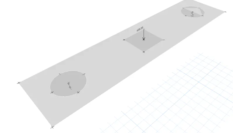
=>Dead Load=438.55 KN
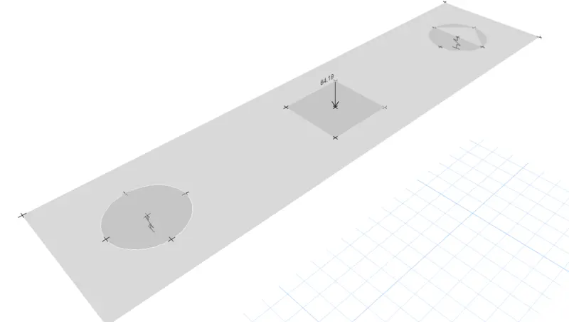
=>Live Load=64.19 KN
Point Spring Modulus=A X E/L=(3.14X250X250)X25000/10000=490625 N/mm=490625 KN/m
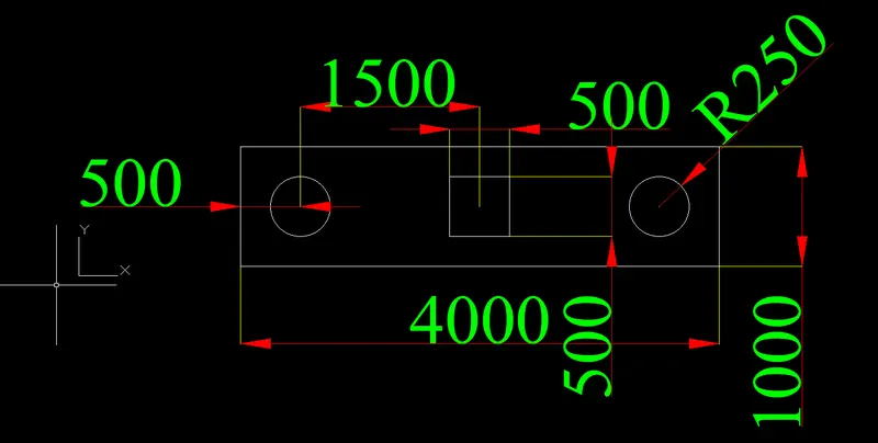
No. of Piles=Load on Column/Pile Capacity=502.74/280=1.79=>2 Piles
c/c Distance b/w Piles and Column=3Xd=3X500=1500 mm
Edge Distance=d=500 mm
Pile Cap Depth=600 mm
So,we use the given layout for the placement of piles.
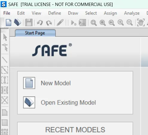
Intially,we go with New Model after going to the SAFE software.
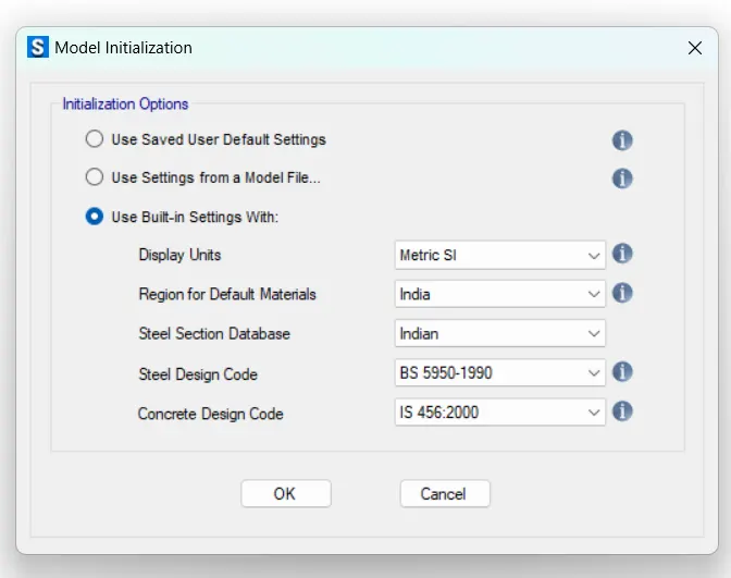
Where we initialize the new model using the Model Initialization Tab.
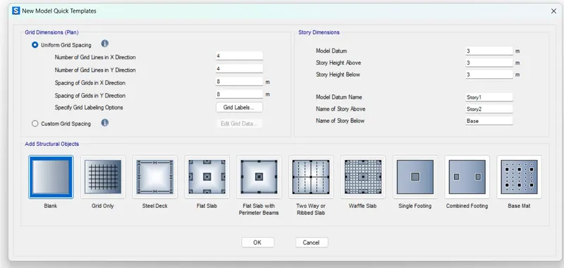
Where we then select the Blank Template in the New Model Quick Templates Tab.
After the opening of the template,the first thing to be done is the creation of the materials using which we do create the remaining.
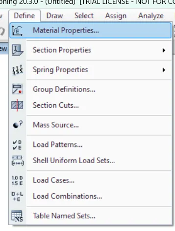
To create the materials,we go to Define Tab>Material Properties...
Where we then add the required materials.
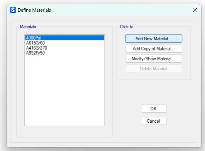
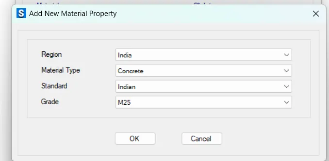
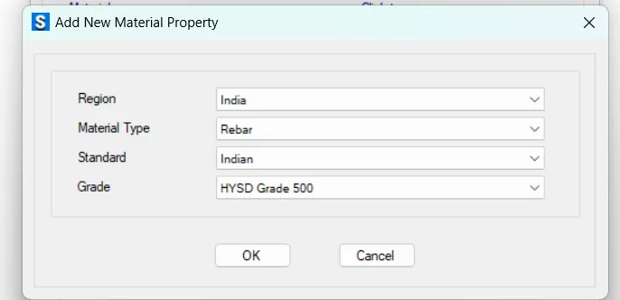
After the creation of the materials,we go with the creation of the sections,where we go to Define Tab>Section Properties>Slab Sections... to create the footing slab.
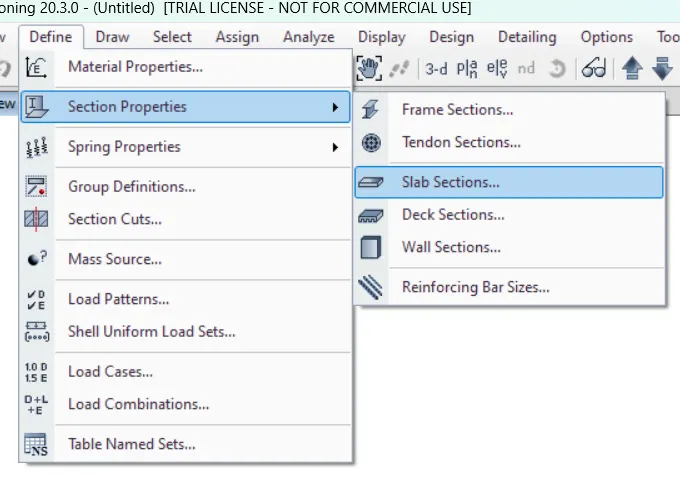
Where we then add a new section with the name PILE CAP 600.
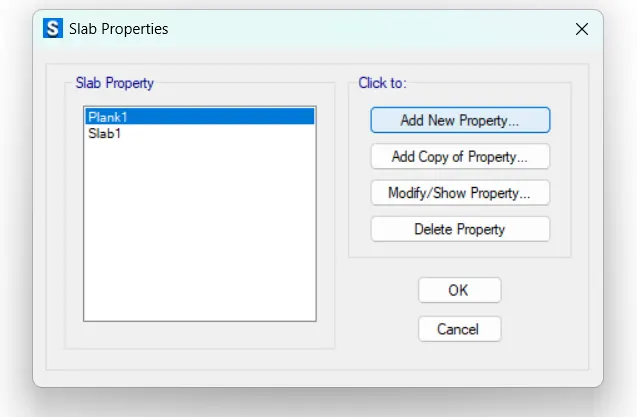
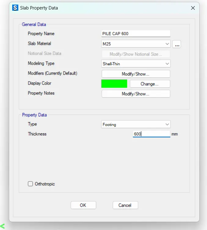
We even add stiff members are required.
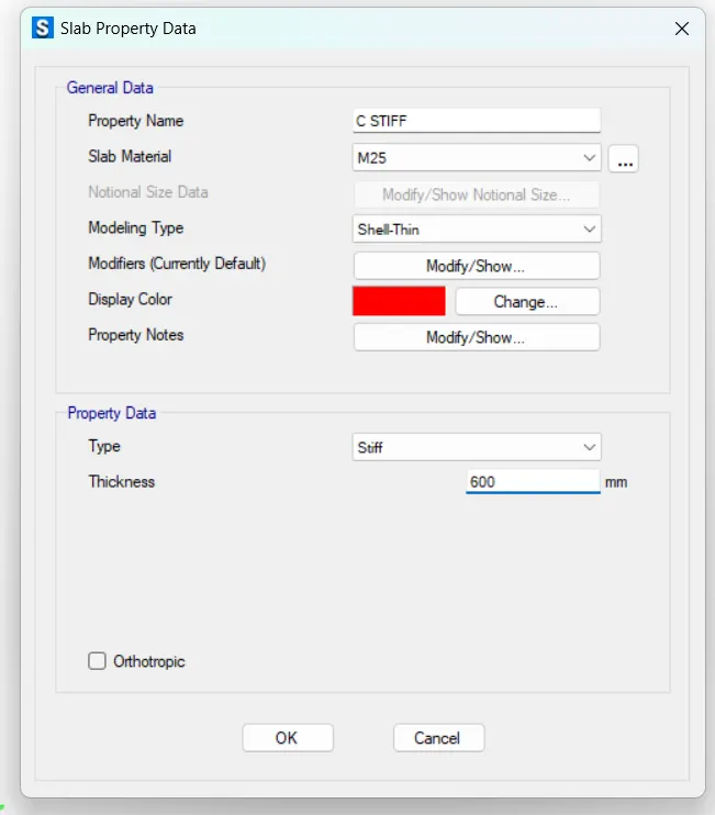
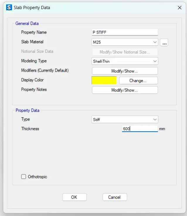
Then we go with the definition of the spring which is very important in the pile cap designing.
Where we go to Define Tab>Spring Properties>Point Springs...
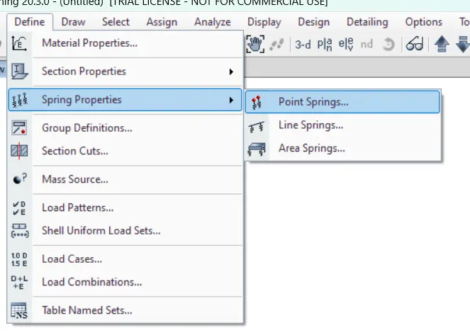
We then add the required spring with required parameters.
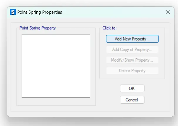
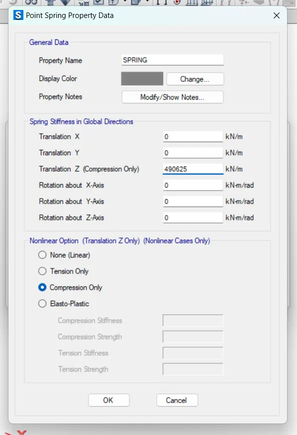
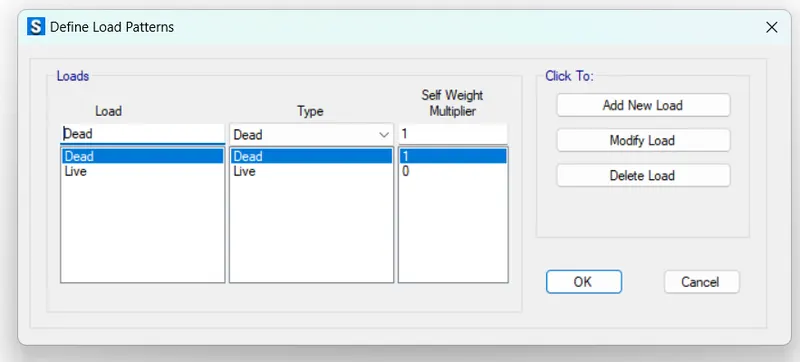
Where we then continue with the definition of the load patterns.
To do that,we go to Define Tab>Load Patterns...
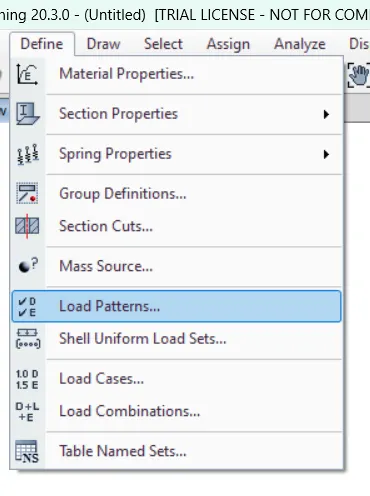
And then add the required loads.
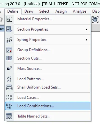
Where then we create the load combinations,so,in the similar manner,we go to Define Tab>Load Combinations...
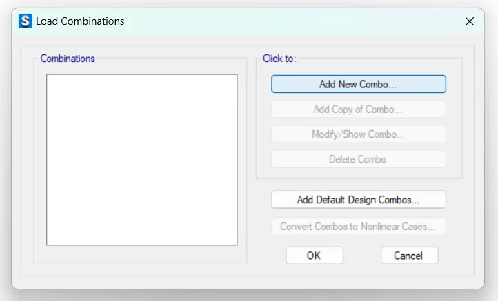
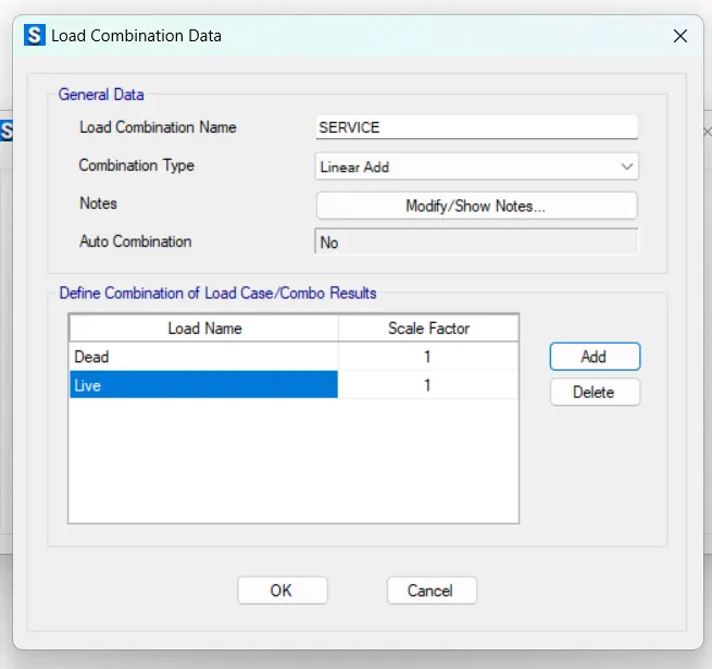
And add the required combo.
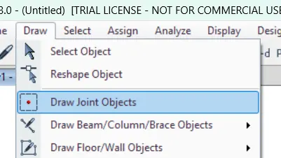
Now,we continue with the drawing of the footing.
We use the option of Draw Joint Objects.We go to Draw Tab>Draw Joint Objects
Initially,we place a joint over the screen.

Where using the first point,we do replicate them.
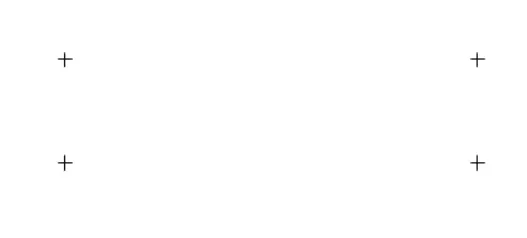
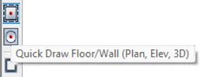
After the creation of the corner points,we use the option of Quick Draw Floor to get a footing.
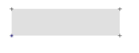
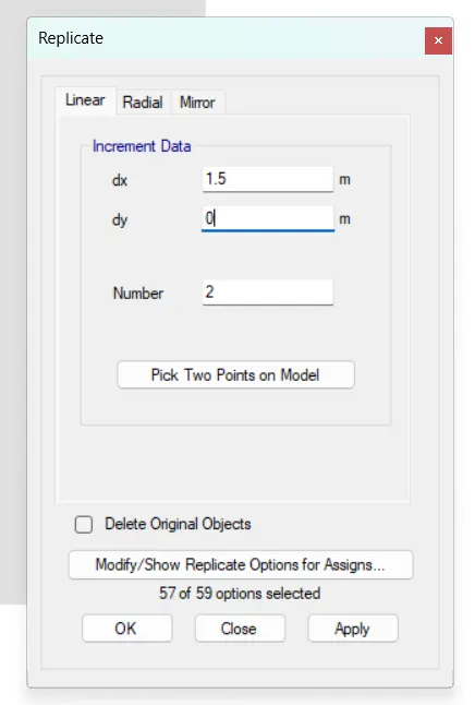
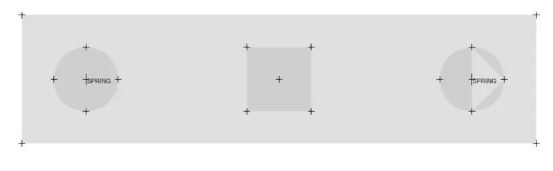
And then we even create the remaining points for the placement of the piles and column.
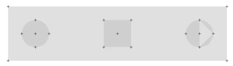
Where we use the option of Quick Draw Area Around Point to place the stiff members for the piles and column.
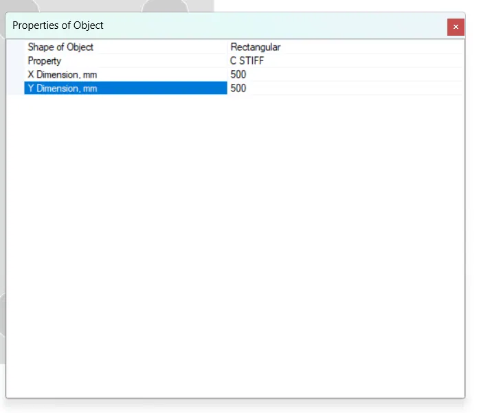
We do check whether the footing is of required property wherever required or not.
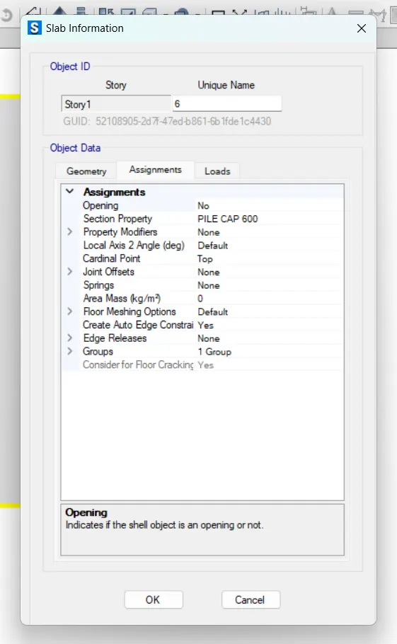
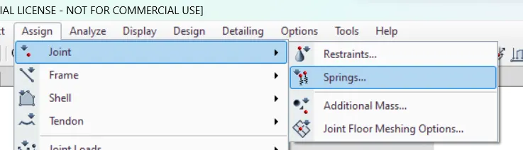
We then assign the springs to the piles,by the process as going to Assign Tab>Joint>Springs...
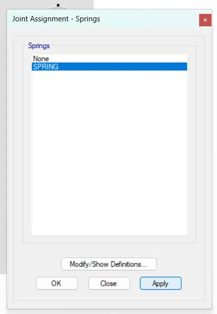
And select the relevant spring.
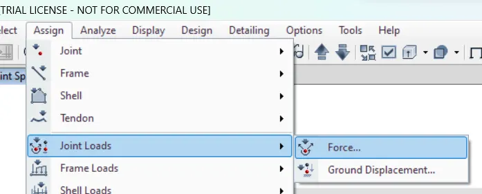
Atlast,we assign the loads to the column.
We go to Assign Tab>Joint Loads>Force...
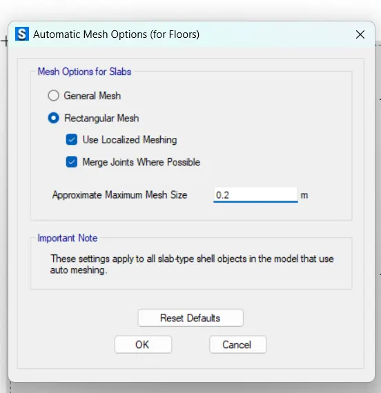
Where we even use the mesh for the equal distribution of the loads.
To do that,we go to Analyze Tab>Automatic Mesh Settings for Floors...>Rectangular Mesh.
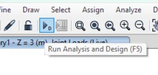
And finally analyze the model.
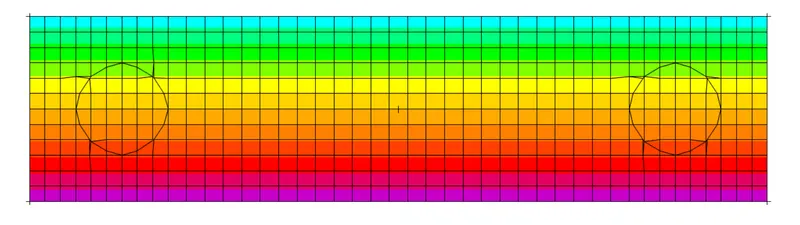
Settlement
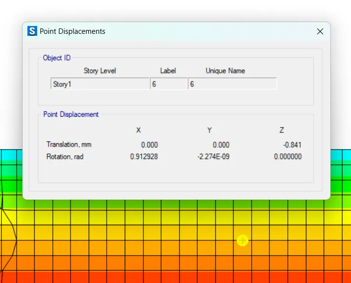
We check for the settlement of the pile cap by selecting any point and right clicking on it to the settlement values.
Punching Shear
We go to Display Tab>Show Punching Shear Design...
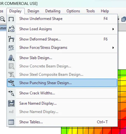
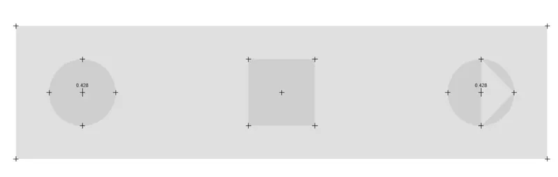
Where all the values are below 1 indicating that it's safe.
Individual Pile Load.
And we check the individual pile capcity by going to Display Support Reactions...
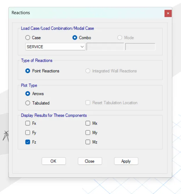
Where we can find that the load acting on the pile is within the limit.
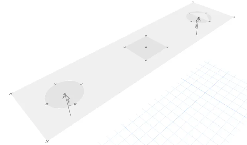
Reinforcement
Where we have to design the reinforcement for the pile cap.
So,we have to draw the design strips using the option of Draw Design Strips.
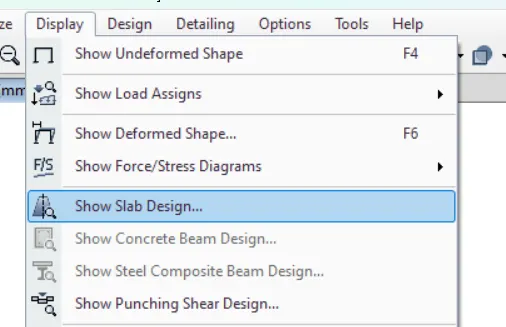
After drawing the design strips,we go to Display Tab>Show Slab Design...

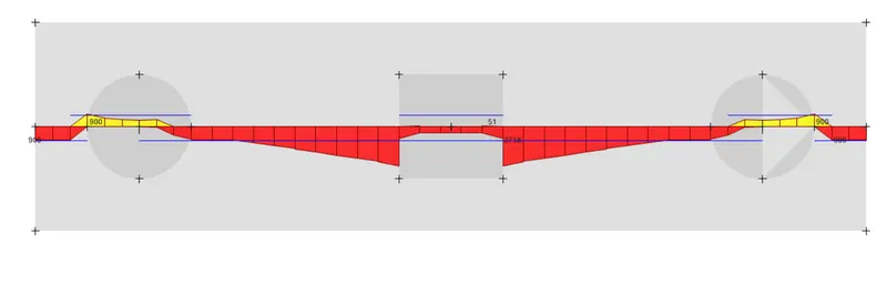
Bottom Reinforcement=2718 sq mm
Top Reinforcement=900 sq mm
Where basing upon the above values we do caluculate the no. of bars required.
We use the 20 mm dia bars for the bottom reinforcement and 16 mm dia bars for the top reinforcement.
20 mm=>3.14X10X10=314 sq mm
16 mm=>3.14X8X8=200.96 sq mm
For the bottom reinforcement,
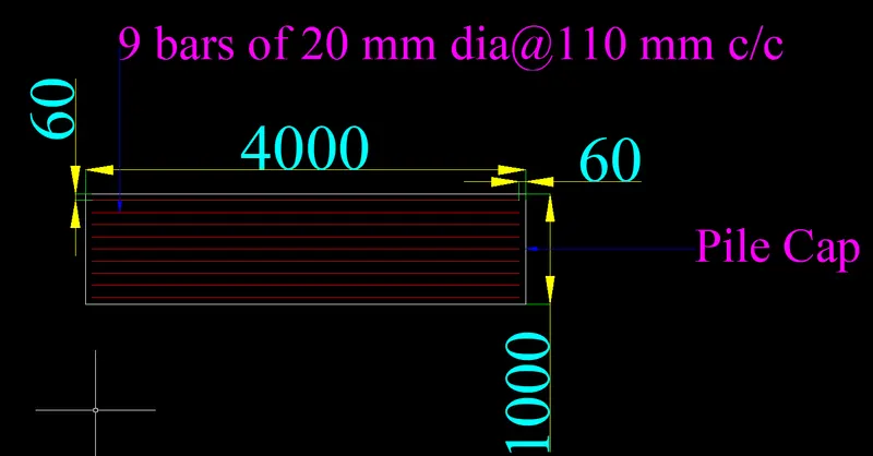
2718/314=8.65=>9 bars
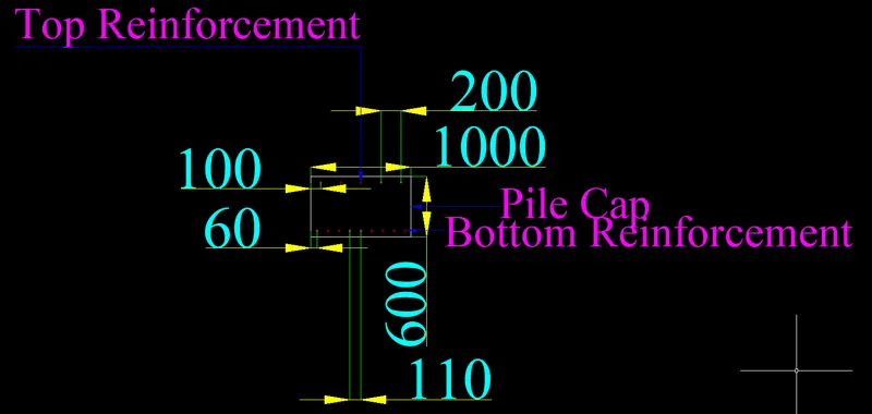
1000/9=111.11 mm=>110 mm c/c
So,we provide a cover of 60 mm on both sides.
Ast provided=314X9=2826 sq mm>2718 sq mm
For the top reinforcement,
900/200.96=4.47=>5 bars
1000/5=200 mm c/c
So,we provide a cover of 100 mm on both sides.
Ast provided=200.96X5=1004.8 sq mm>900 sq mm
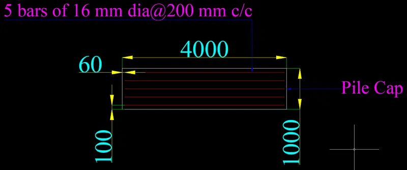
And we can even find the sectional view of the bars.