Project 2_Design & Analysis of a Hostel building at Guwahati, Assam
Aim: Design & Analysis of a Hostel building at Guwahati, Assam.
Introduction :
ETABS is an engineering software product that caters to multi-story building analysis and design. Modeling tools and templates, code-based load prescriptions, analysis methods and solution techniques, all coordinate with the grid-like geometry unique to this class of structure. Basic or advanced systems under static or dynamic conditions may be evaluated using ETABS. For a sophisticated assessment of seismic performance, modal and direct-integration time-history analyses may couple with P-Delta and Large Displacement effects. Nonlinear links and concentrated PMM or fiber hinges may capture material nonlinearity under monotonic or hysteretic behavior. Intuitive and integrated features make applications of any complexity practical to implement. Interoperability with a series of design and documentation platforms makes ETABS a coordinated and productive tool for designs which range from simple 2D frames to elaborate modern high-rises.
- Etabs is totally run based on the IS codes which are IS - 456 ,IS - 800 , IS 1893..
SAPFire® Analysis Engine (Slab Analysis by the Finite Element Method)
CSI solvers have been tried and tested by the industry for over 45 years. The SAPFire Analysis Engine can support multiple 64-bit solvers for analysis optimization and can perform both eigen analysis and Ritz analysis. Parallelization options are available to take advantage of multiple processors.
- SAFE offers a single user interface to perform modeling, analysis, design and reporting. A new model explorer is available for quick access to objects, properties and forms.
- SAFE is ideal for modeling foundations, basemats, and footings. Easily model soil supports and zero tension soil models with uplift analysis. The area assignment of soil supports is based on the subgrade modulus, and they automatically adjust whenever the mesh changes. Basemat foundation models can include pedestals, walls, columns, beams, and piles in addition to the foundation area.
- Design strips are used to define how reinforcement requirements are to be calculated. SAFE can automatically define the strips for you, or you can define them yourself.
- SAFE includes the ability to define post-tensioning in slabs, as banded or distributed tendons. An interactive tendon editor simplifies the task of laying out the tendon profiles. Tendon layouts can also be automated based on strip position and direction. also provides a wide range of code-based design features for reinforced concrete and PT beam, slab design and composite steel beams.
- Laying out models is quick and efficient way with the user-friendly drawing tools, or user can import model layouts from AutoCAD or loading conditions from other software's like CSI ETABS and CSI SAP2000.
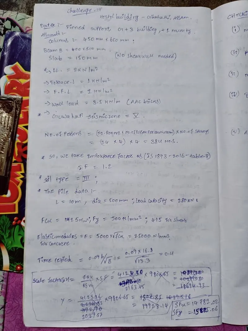
In this project, participants will get to experience the entire design process from modelling, analysis, design, and preparation of construction drawings. The architectural drawings of a G+3 RCC building is provided. The following information on the building is to be used:
- Location – Guwahati, Assam
- Function – Hostel block in an academic institute
The walls will be made of AAC blocks. Other loadings are to be calculated as per the architectural drawings.
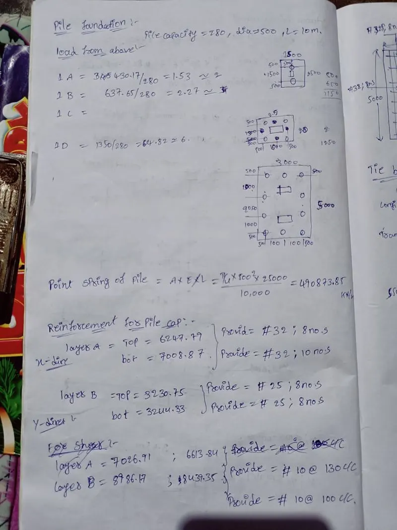
The buildings rests on type 3 soil. Piles of length 10 meters and 500 mm diameter with a load-carrying capacity of 280 KN is to be used.
The ground floor level will be at a height of 2 meters above the existing site level to avoid floodwater enter the building.
M25 grade of concrete with Fe500 for longitudinal reinforcement and Fe 415 for shear reinforcement is to be used.
the architectural model and elevation will be given in to attachments.
The following design IS codes will be required for reference:
- IS 875 part 1
- IS 875 part 2
- IS 13920
- IS 1893
- IS 2911 part 2
- IS 456
- SP 34
Students will have to produce the following:
- Etabs model for the two blocks on either side of the expansion gap
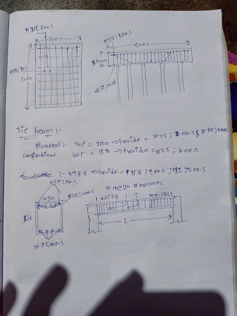
- Foundation details illustrating the pile & pile cap reinforcement
- Tie beam details connecting the pile caps
- Column reinforcement
- Framing plan for typical floor
- Beam reinforcements for ground floor
Procedure :
- open the Etabs software create new sheet with built in settings units are metric SI .
- create the grids in x direction and in Y with the specified spacing.
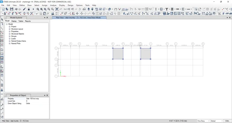
- enter the story data and ceate 4 stories each with 3 .45m height and mumty level as 2.5 m height .
- define the the material properties of concrete as M25 grade and steel as HYSD 415 ,500.
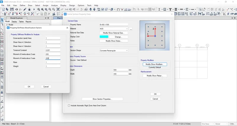
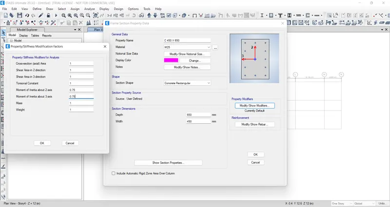
- define the section proerties of frame properties are Beam size is 400 X 500 mm and columnn size is 450 x 650mm .
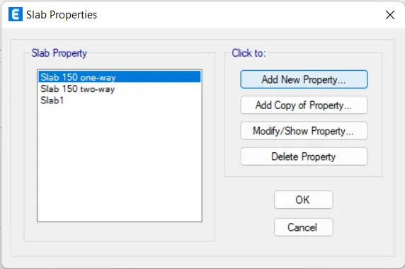
- similarly define the slab properties are thickness is 150mm and for oneway slab thick is 150mm with the one way load distribution.
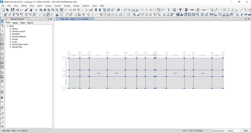
- next , use quick drawa option draw the columns,beams,slabs (which are not assign to base and plinth stories) based on the grids and spacing from the architecture drawing.
- after that then we have to assign the joints at the bottom of columns ,go to base level plan and select every connection then go to assign tab restrains choose the restrains as fixed.
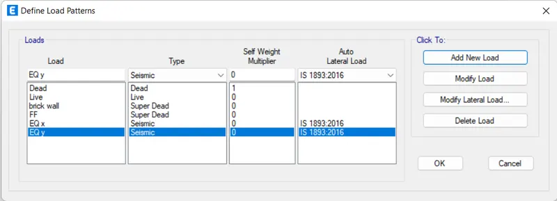
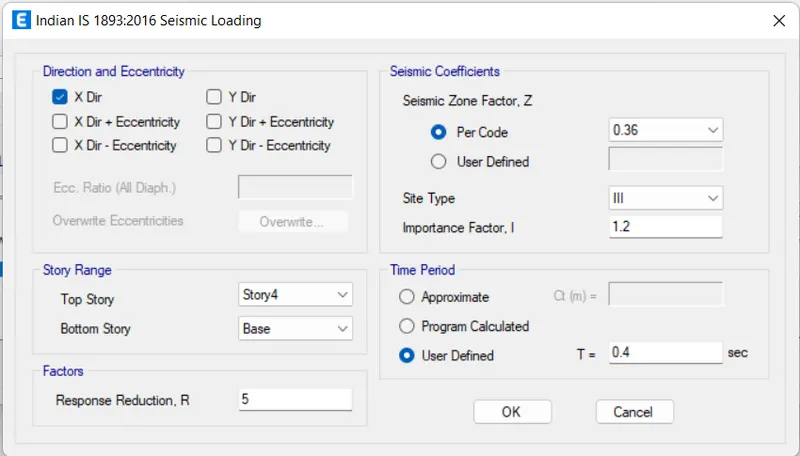
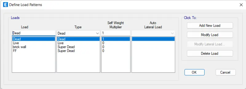
- next,define the load pattrens as dead ,live load , brickwall,finishes (superdead load) ,EQ x,x+,x- and EQ y ,y+,y- those are seismic loads .
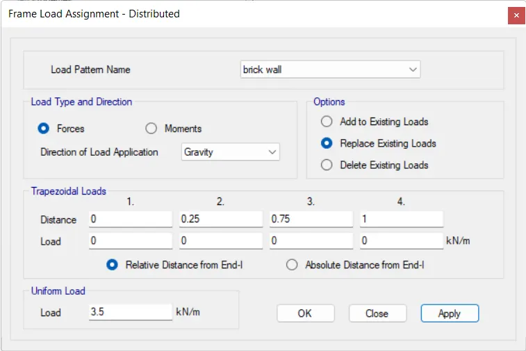
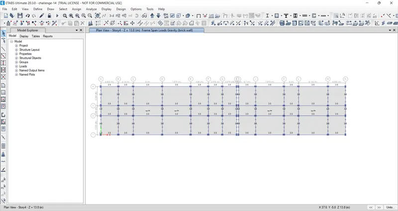
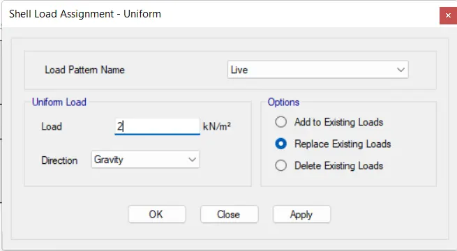
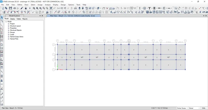
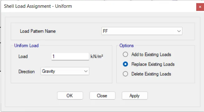
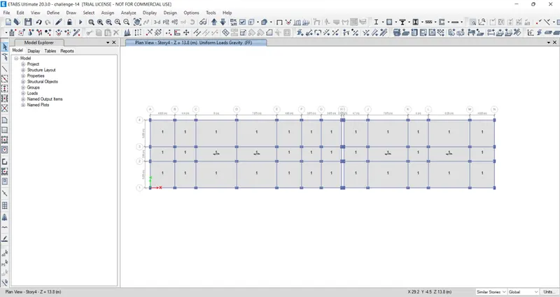
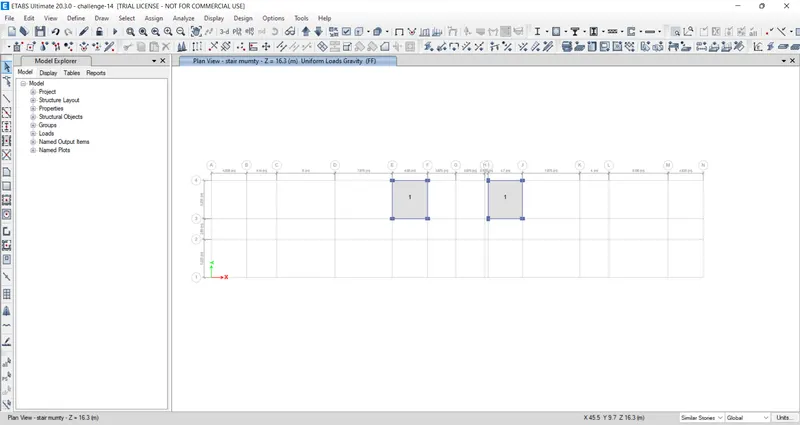
- after that assign the loads - frame loads to beams which are wall loads with 3.5 kN/m ( why because those are given AAC blocks) and shell loads to the slabs which are live loads with 2 kN/m2 and 3 kN/m2 and also give finishes as 1kN/m2.
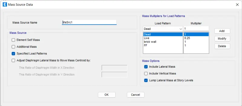
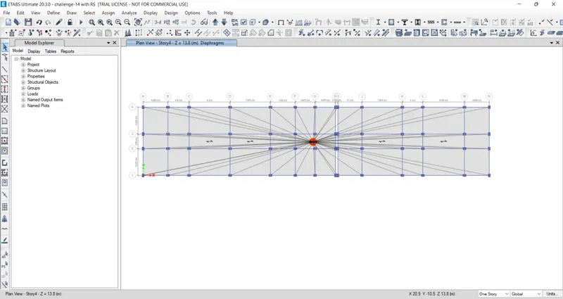
- also assign the mass sources to the all stories.and assign diaphrams to the floors for centre of mass for slabs.
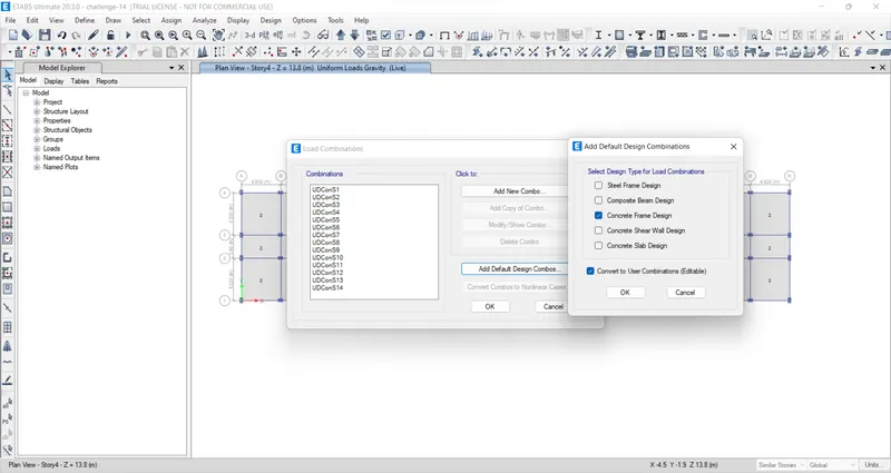
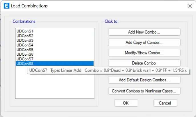
- add the load combinations as default.
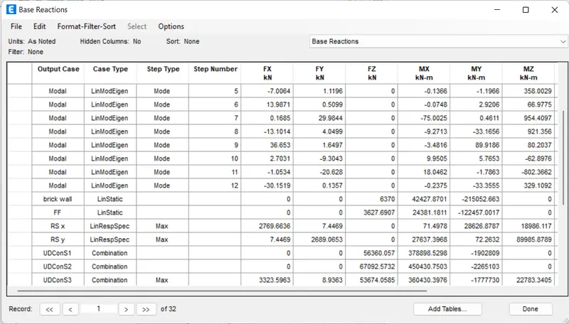
- then run analysis the model.checj the results for base reactions table for EQ x and y.
- then save the model and save the another model.
- open the saved model and delect the EQ loads and here we add the response spectrum,go to define - functions-response spectrum-create the IS funtion as per the seismic zone -5.
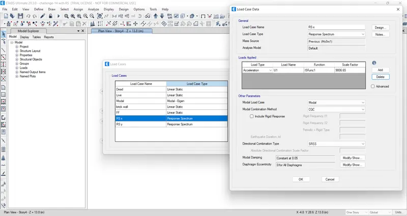
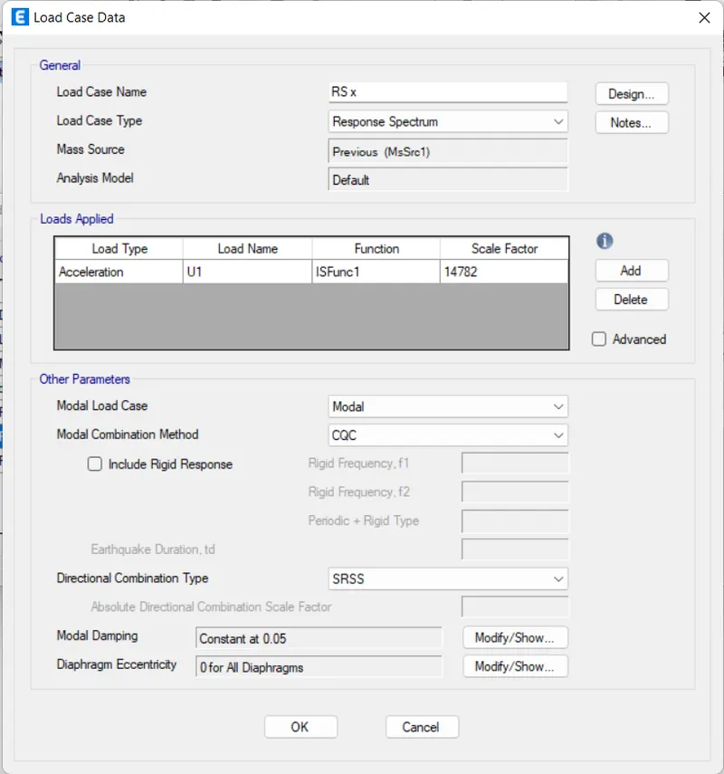
- then go to load cases add load cases RSx and RSy with the normal scale factor.
- then modelling is completed start the run analysis (F5).
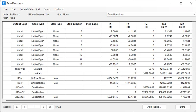
- check resulsts of base reactions in the table,check EQx and RSx are having similar Fx values .if not we do the calculation and change the scale factor until it achives.
- Results are given below.
- after that will be completed ,save as the model with RS .
- then again run an analyze the structure with only Gravity and RS load cases.
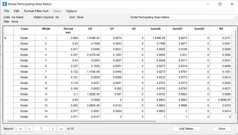
- check the results in the tables. which are uploaded in below as snaps.
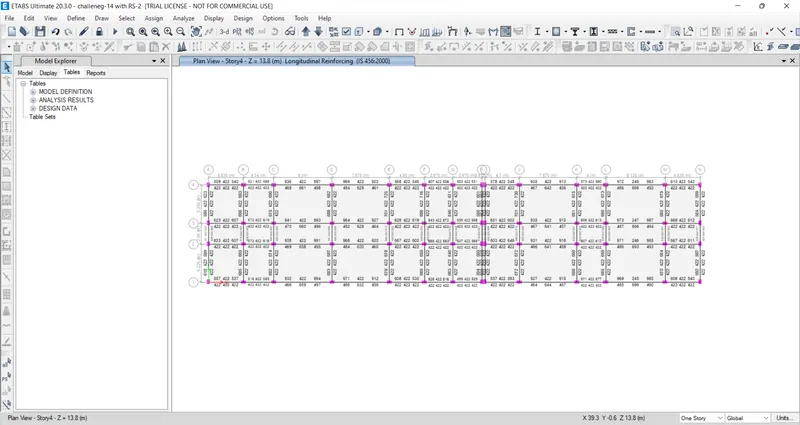
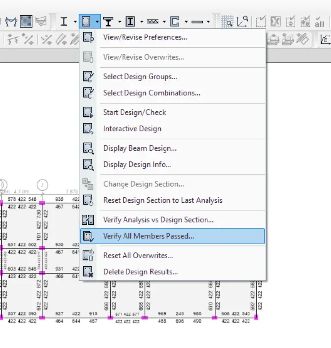
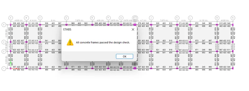
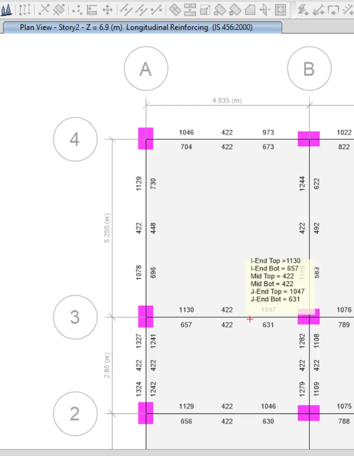
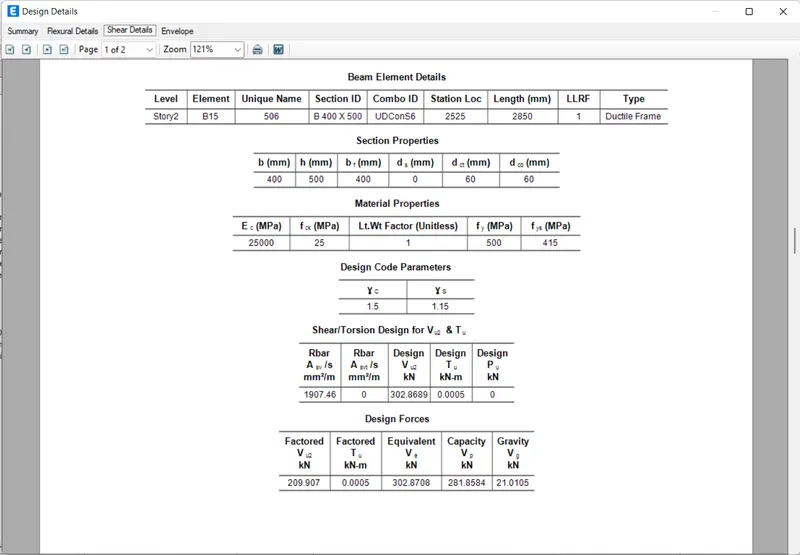
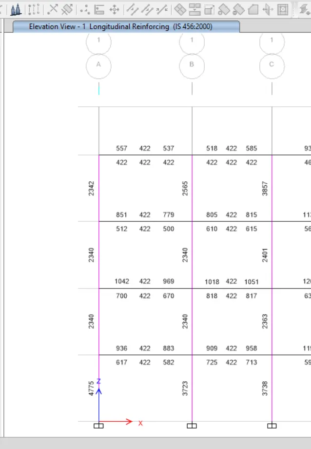
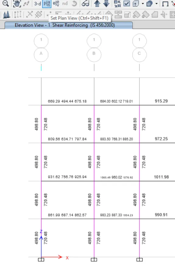
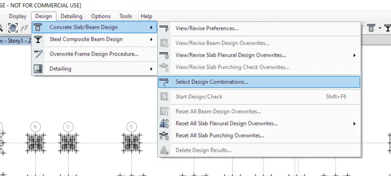
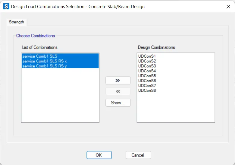
- next design the concrete members and check the all members are passed or not. of passed the provided sizes are sufficient.then proceed to design.
- then design the beam and column .
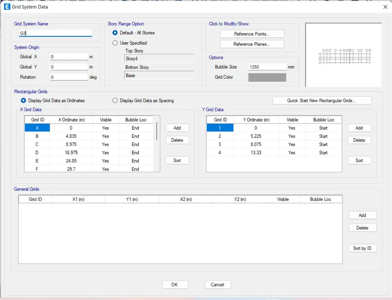
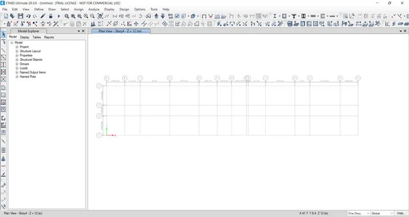
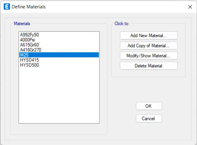
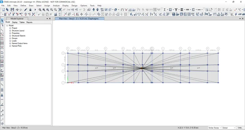
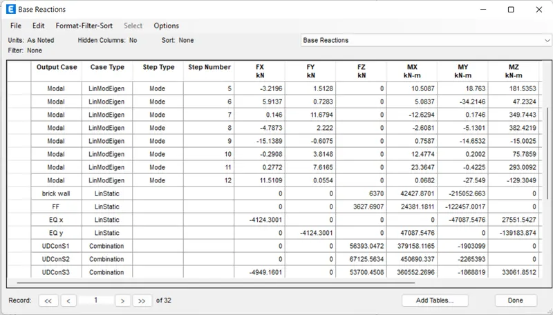
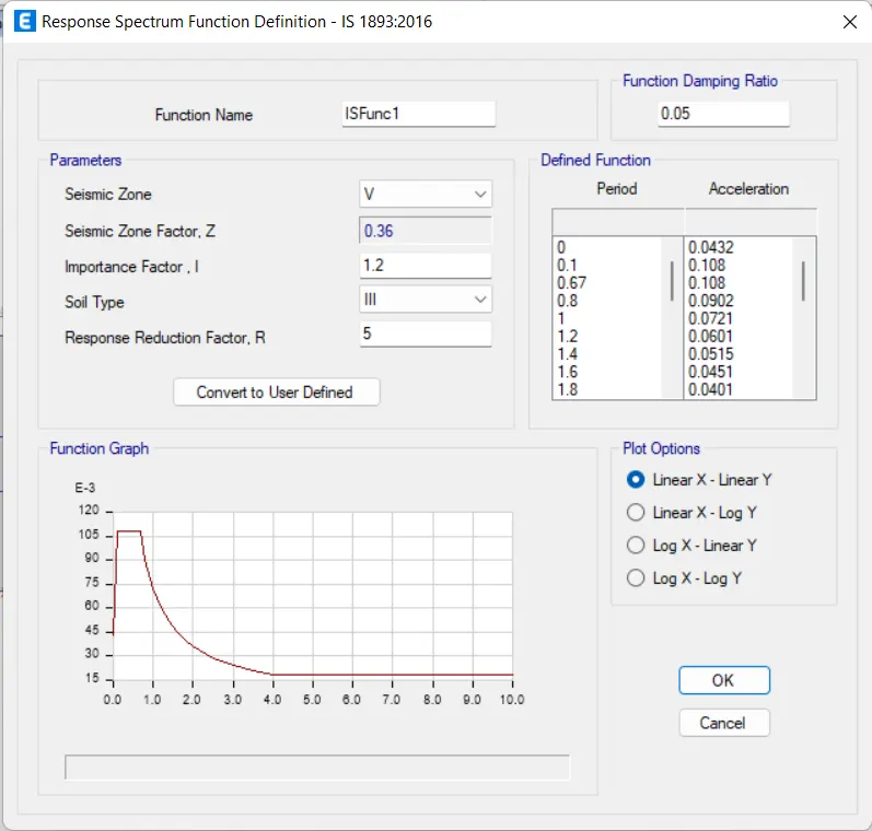
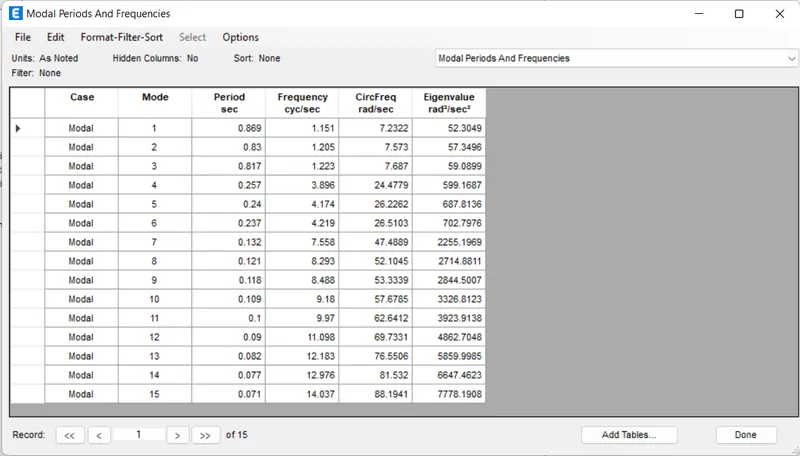
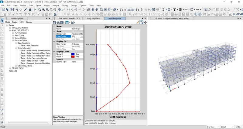
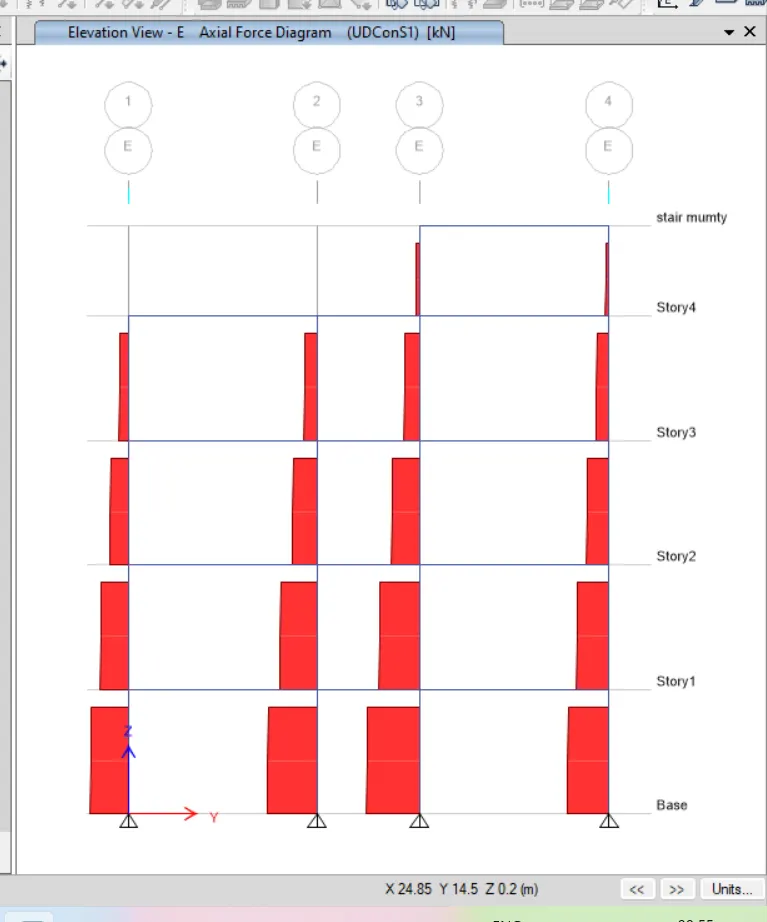
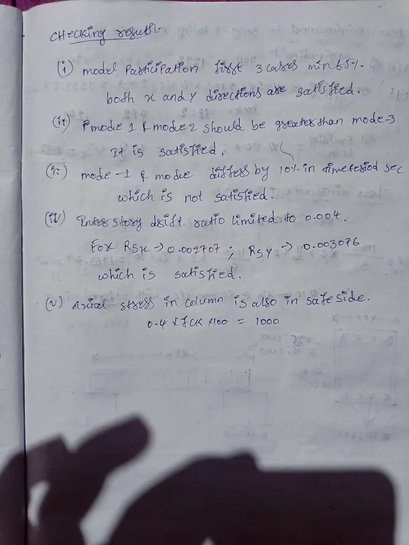
- next design the concrete members and check the all members are passed or not. of passed the provided sizes are sufficient.then proceed to design.
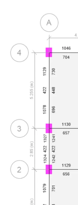
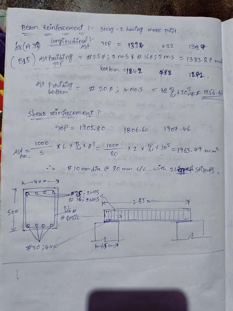
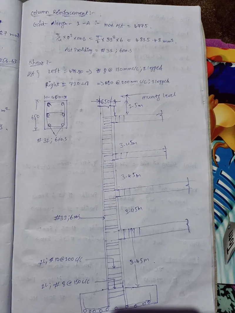
- then design the beam and column details from the achieved reinforcement longitudinal and shear .
- Draw the reinforcement details for designed beams and columns.
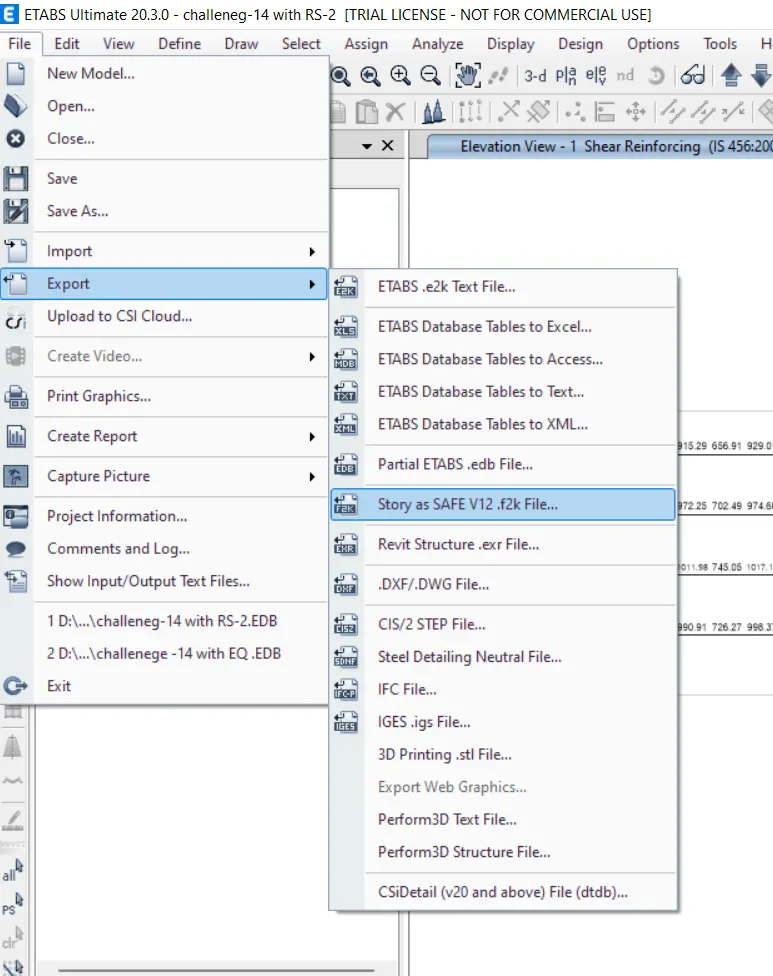
- ater that export the etabs model to the SAFE model.
Procedure for footing in SAFE :
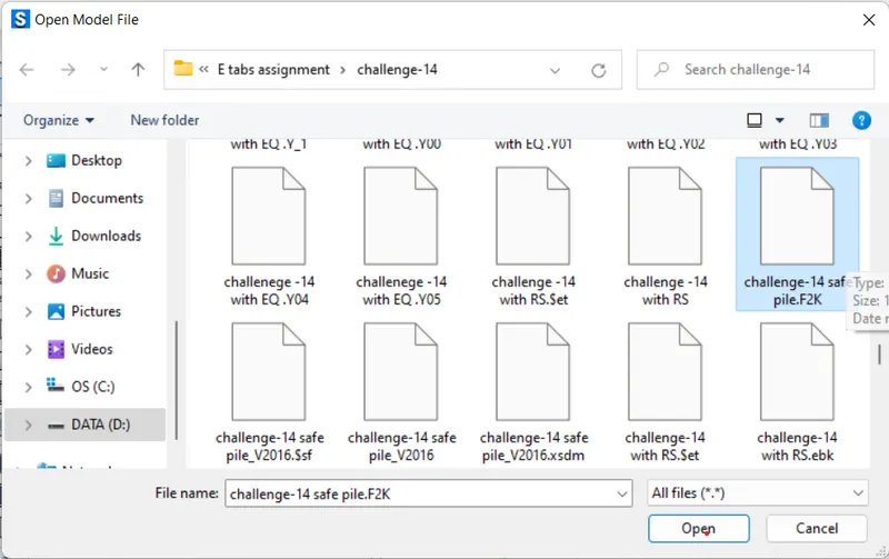
- open the exported safe model software.
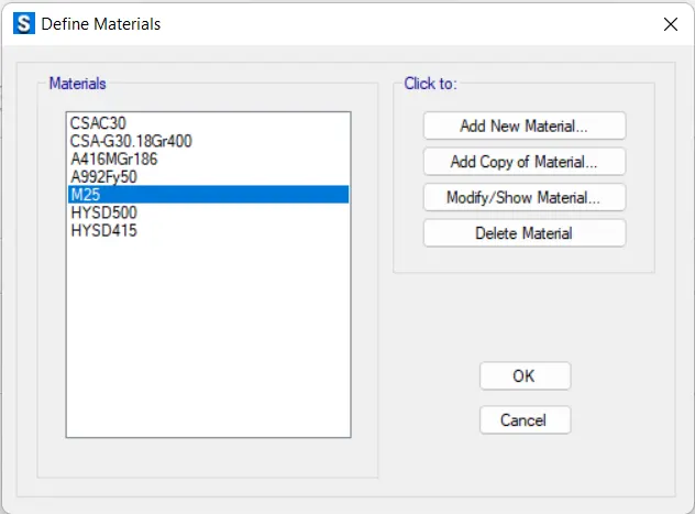
- the material properties such as M25 concrete,Fe500 rebar.
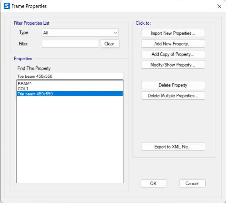
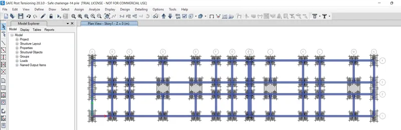
- define the tie beam as 450 x 650 mm in frame sections.
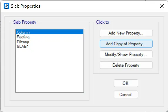
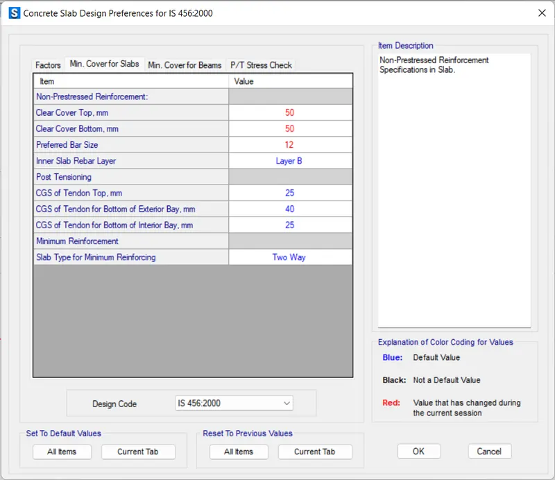
- define the slab properties,column (stiff) , footing and pile cap (MAT).
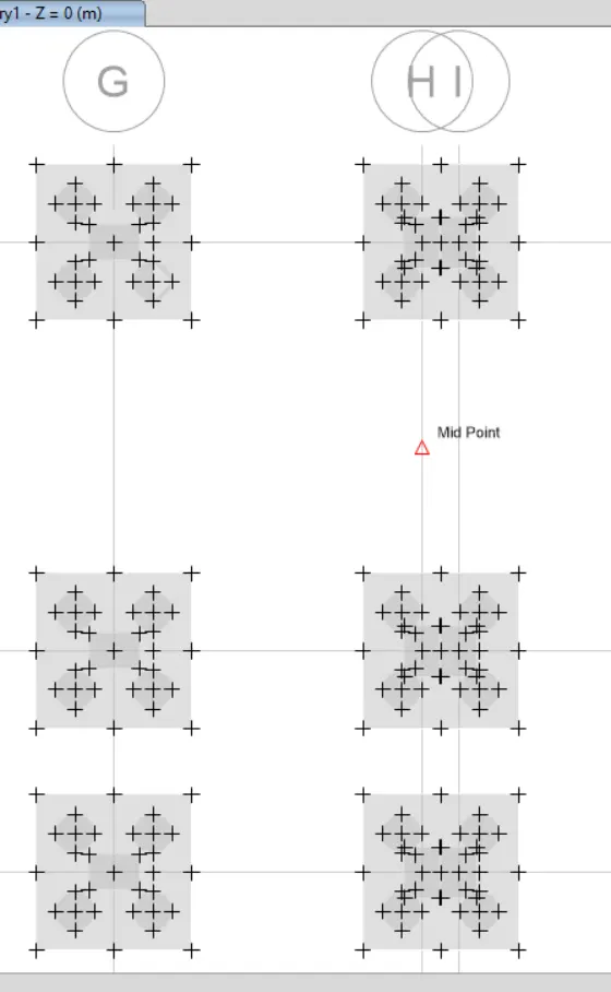
- draw the footings and columnns and pile caps in their places.
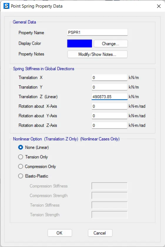
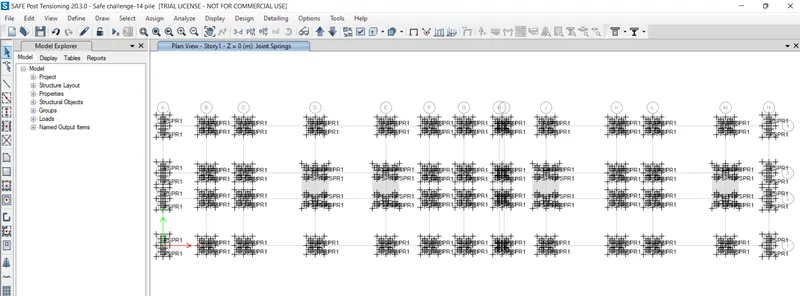
- next add the spring pressure 490873.85 KN/m, in the define ponit -spring properties.
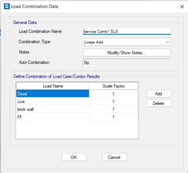
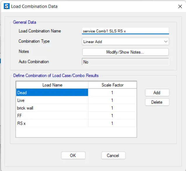
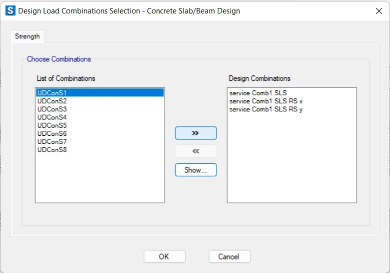
- after that defining the materials we add the load patterens and load combinations (SLS) and SLS with RS x and y
- then we have to check the assign loads to the model which are from etabs model dead above ,live above like that.
- after that we can run the analysis of the model.
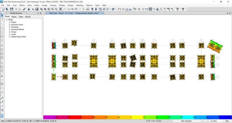
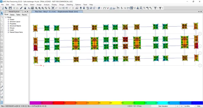
- next,check the displacement below 25mm.
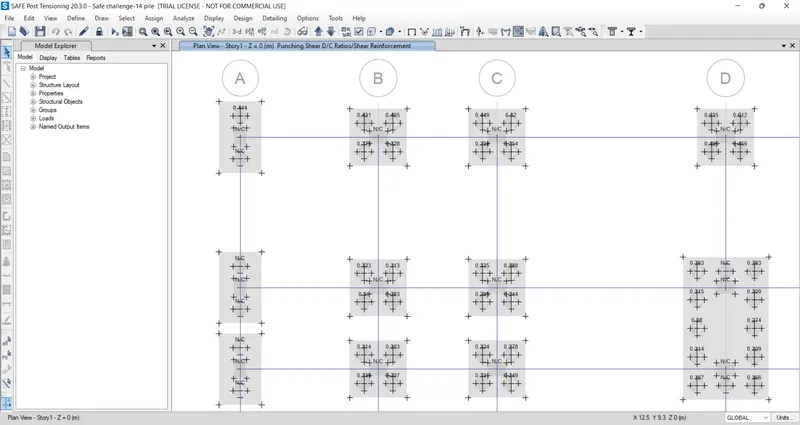
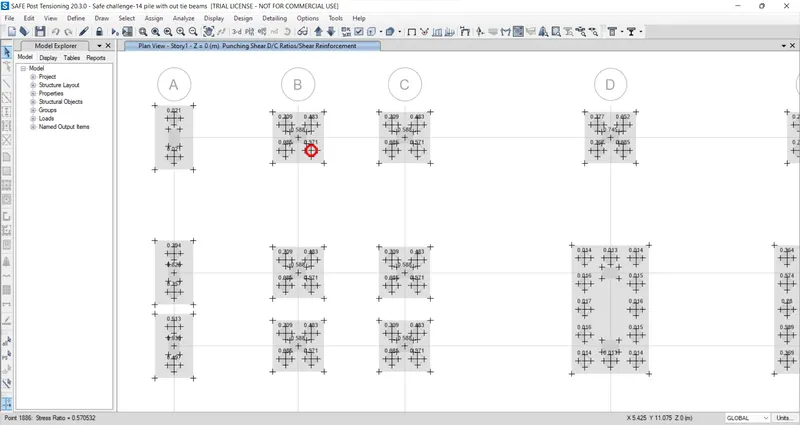
- then check the punching shear that should be below 1 . in this case check as the model with tie bems and with out tie beams.
- after thAT WEW HAVE TO ADD THE STRIPS TO CHECK THE REINFORCEMNET.
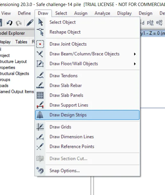
- unlock the model then draw the strips the A and B.
- then again run the model.
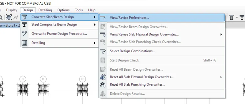
- next click on concrete /slab design button.
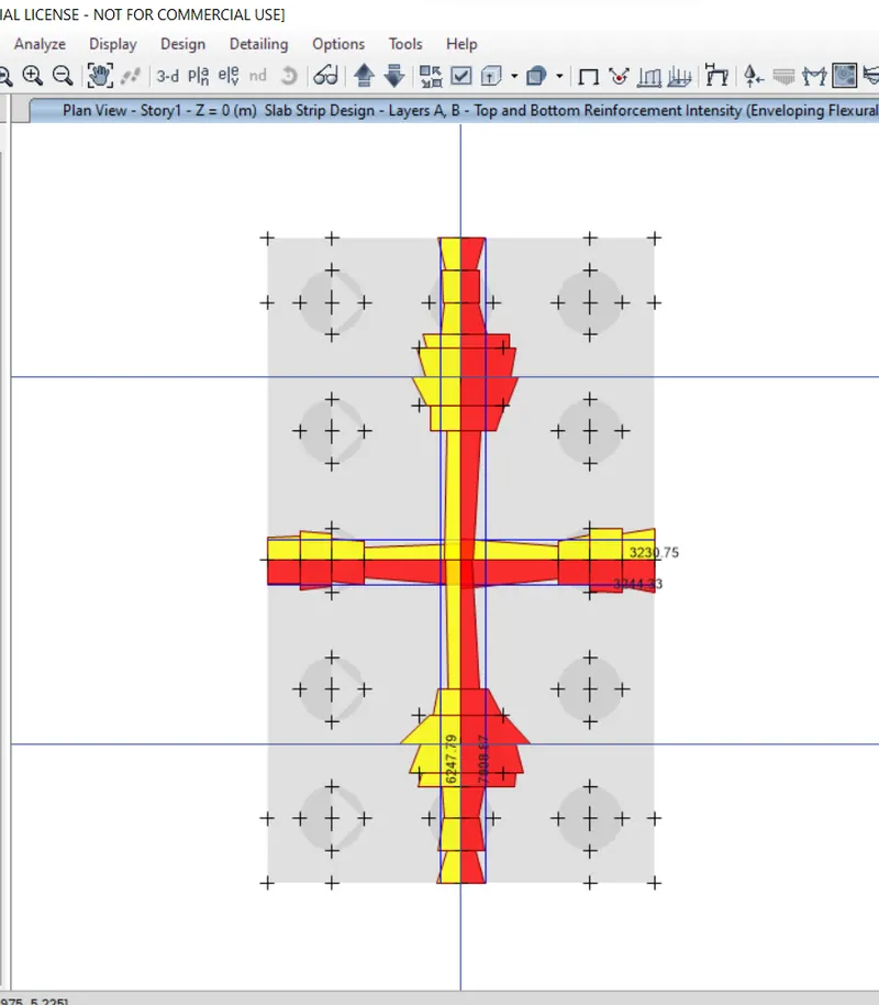
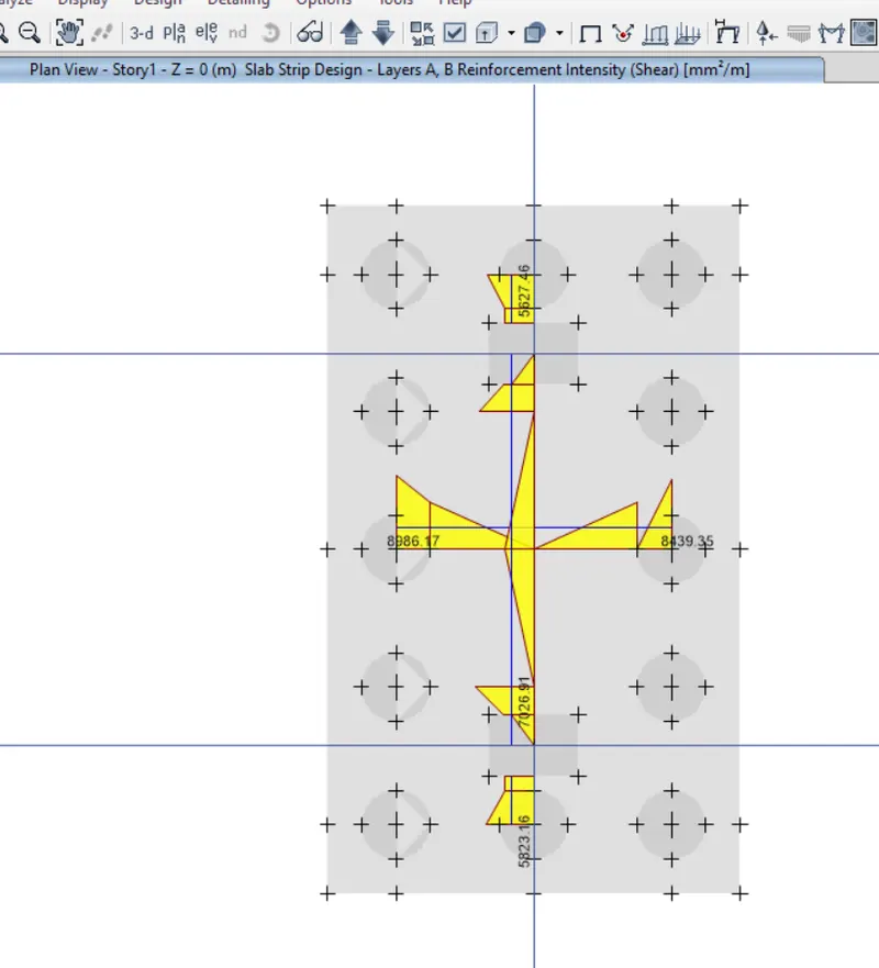
- then you simply go to the display show slab design you can see the reinforcement design simultaneously Layer A and B.
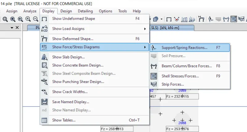
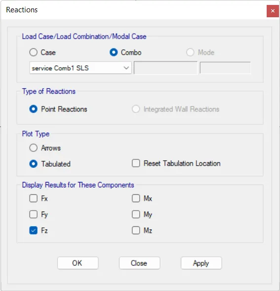
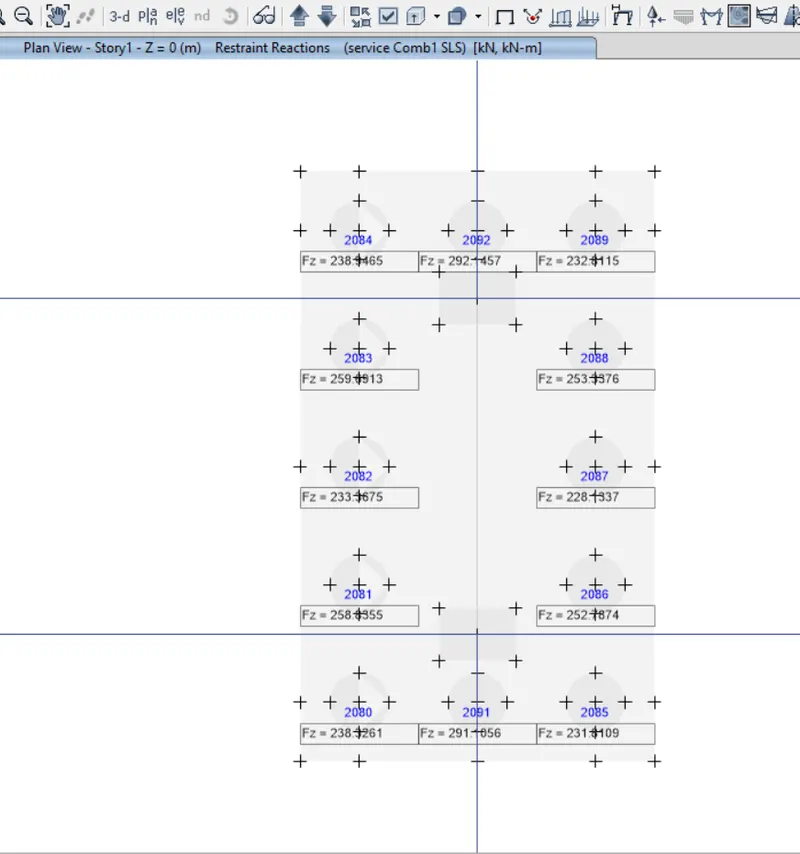
- then based on the results design the pile cap. and check the pile capacity in the support reactions.
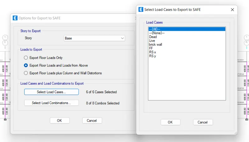
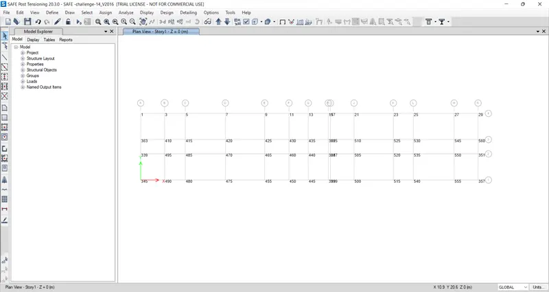
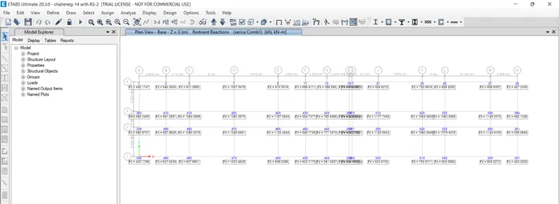
the total service loads (which created in etabs )are used to find the no.of piles .
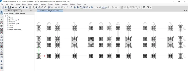
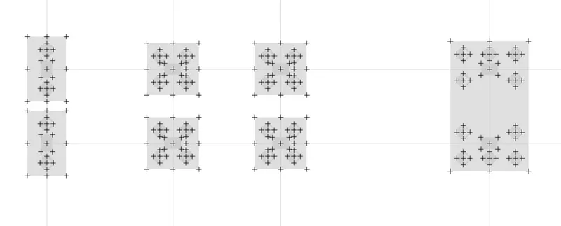
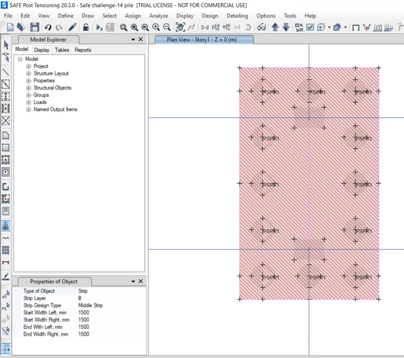
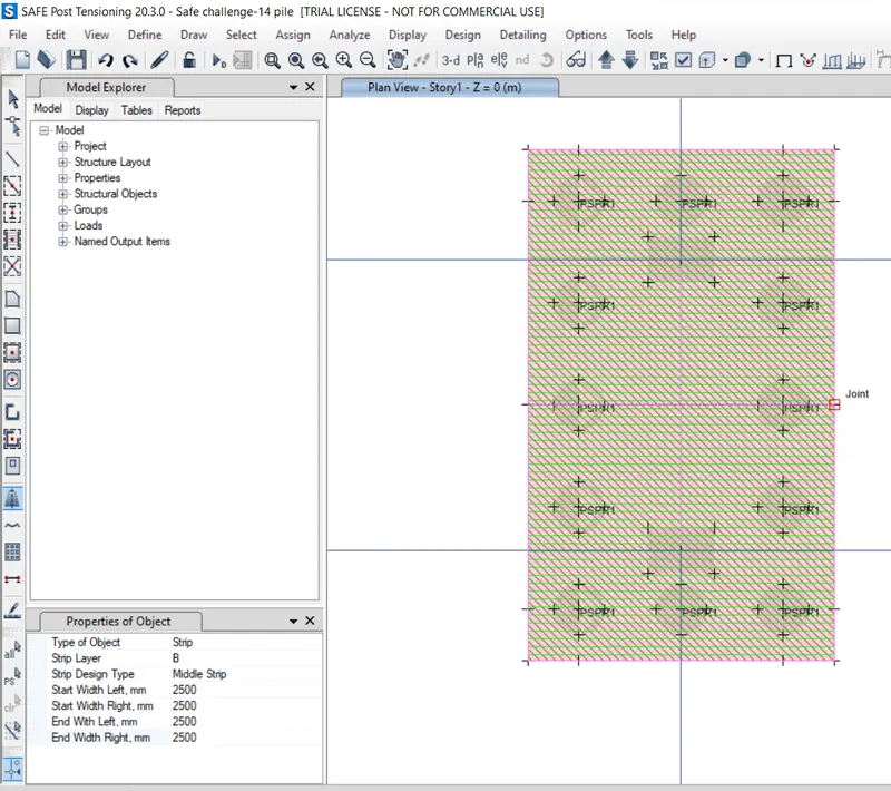
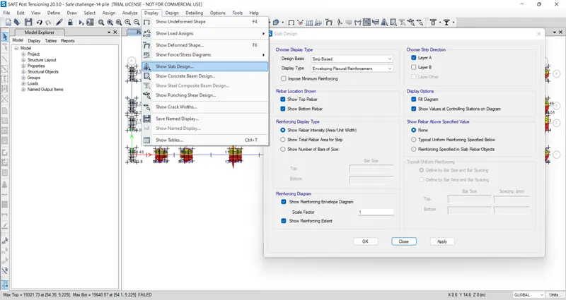
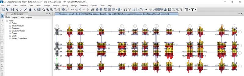
Safe model Rsults :
- the displacement of the model is very small ,that is in limit.
- Punching shear of the pier is also in the limit that should be in below 1.
- the pile capacity also be checked that is also satisfied.
- the pile cap and tie beam are designed .
RESULTS:
- Etabs model created for the two blocks on either side of the expansion gap
- Foundation details illustrating the pile & pile cap reinforcement and Tie beam details connecting the pile caps are designed which are provided as the image.
- Framing plan for typical floor is uploaded above as picture.
- Beam reinforcements and Column reinforcement for ground floor are designed and which are uploaded as image.