Project 2_Design & Analysis of a Hostel building at Guwahati, Assam
AIM: -
To model, analyze and design the given building.
- Location – Guwahati, Assam
- Function – Hostel block in an academic institute
Produce the results of the following:
- ETABS model for the two blocks on either side of the expansion gap
- Foundation details illustrating the pile & pile cap reinforcement
- Tie beam details connecting the pile caps
- Column reinforcement
- Framing plan for typical floor
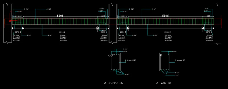
- Beam reinforcements for ground floor
PROCEDURE: -
Given Data
The walls will be made of AAC blocks.
Soil Type: - Type III.
Piles length - 10 meters
Piles Diameter - 500 mm
Piles Capacity - 280 KN
The ground floor level will be at a height of 2 meters above existing site level to avoid flood water enter the building.
Grade of concrete- M25
Grade of Steel – HYSD 500
- HYSD 415
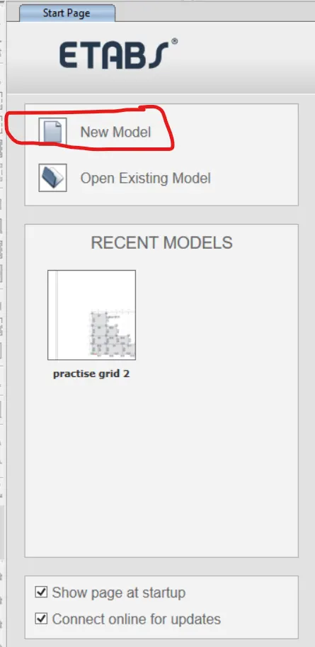
Open ETABS software.
Click on New
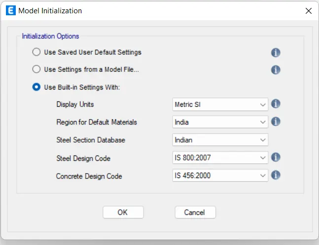
Model Initialization dialogue box opens
Select Use Built-in Settings with:
Display units: Metric SI
Region for Default materials: India
Steel Connection Database: Indian
Steel Design Code: IS 800: 2007
Concrete Design Code: IS 456:2000
Set these changes in the Model Initialization
After setting above changes Click OK
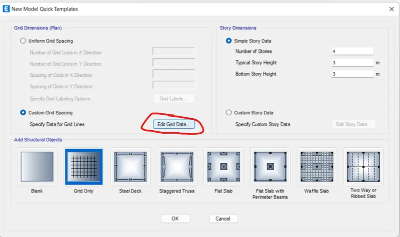
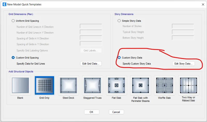
Now, New Model Quick Template dialogue box opens
Select Custom Grid Spacing
Click on Edit Grid Data
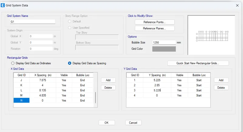
Grid System Data dialogue box opens
Under Rectangular Grids, Select Display grid Data as Spacing
Under X Grid Data column enter the data as per given data
Under Y Grid Data column enter the data as per given data
After entering the Grid Data press OK
Select Custom Story Data in New Model Quick Template dialogue box
Click on Edit Story Data
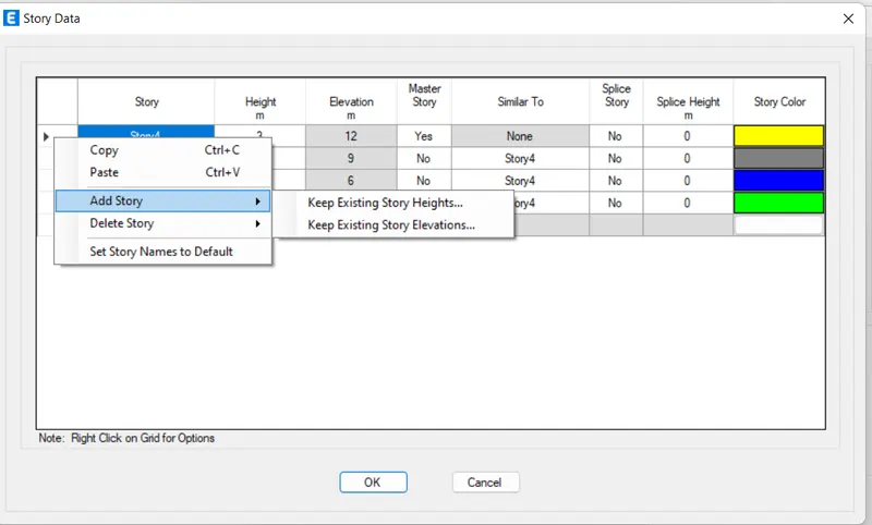
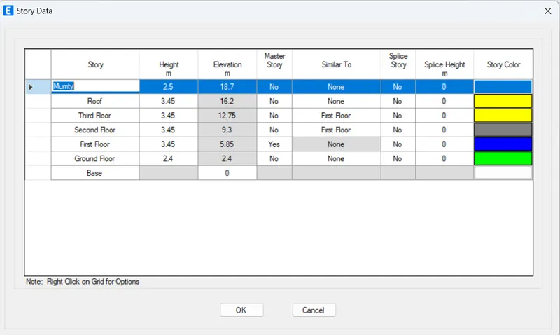
Story Data dialogue box opens
Edit the default storeys
Add Ground Floor in Story column and Height 2.4m in Height column.
Right click on the story 3 and click on Add Story
Select keep Existing Story Heights option
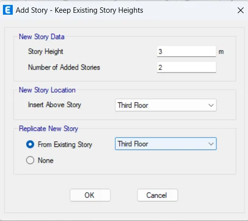
Add Story dialogue box opens
Enter the required data and press Ok
Select YES for the Story1 in Master Story column.
Select Story1 for the rest of the storeys in Similar To column
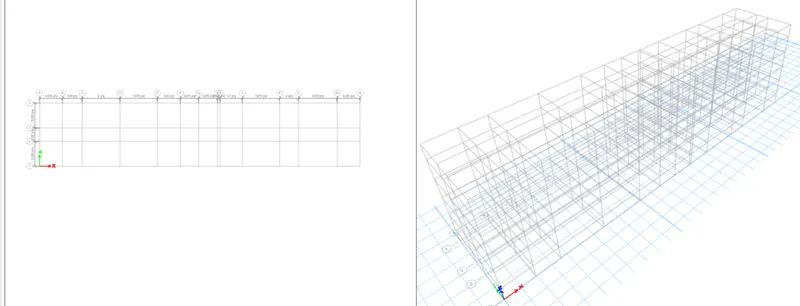
Model appears on the screen
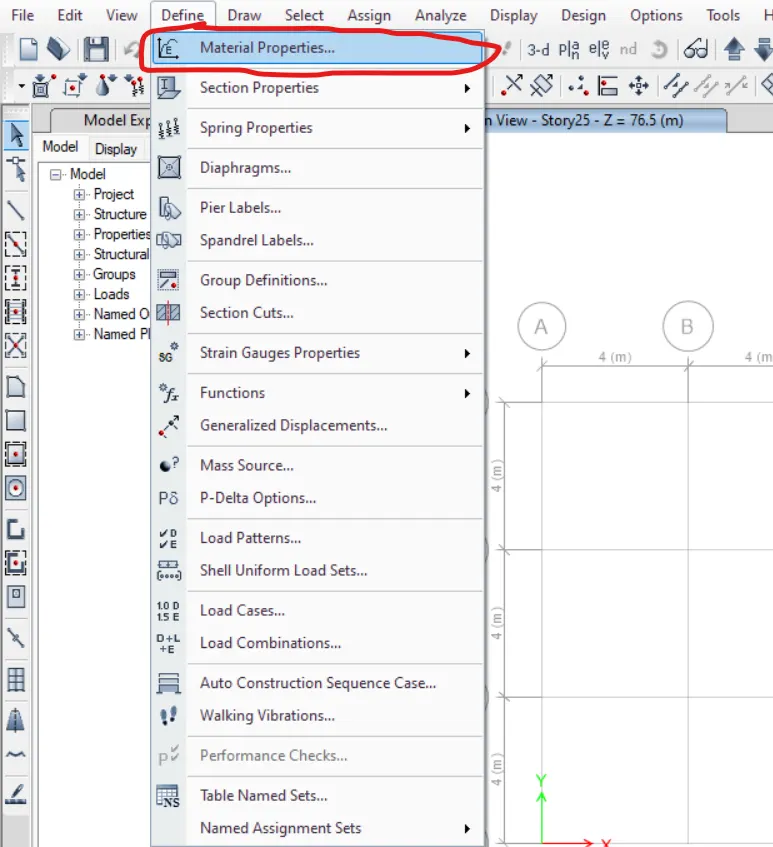
Click on the Define Tab
Select Material Properties
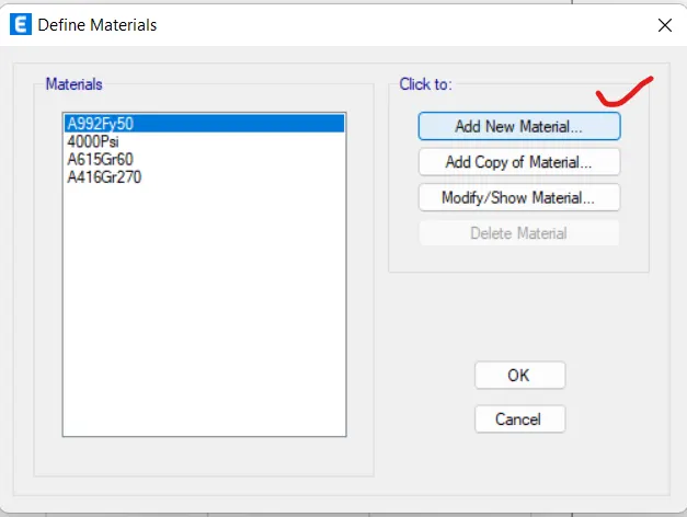
Define Materials dialogue box opens
Click on Add New Material
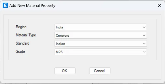
Add New Material Property dialogue box opens
Region: India
Material Type: Concrete
Standard: Indian
Grade: M25
After entering the data, press OK
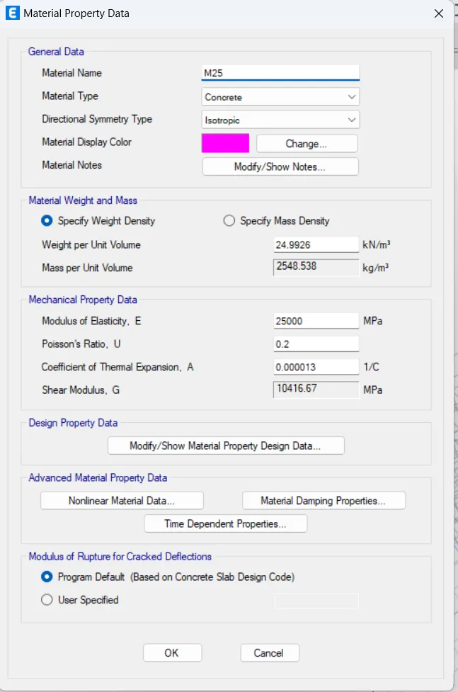
Material Property Data dialogue box opens
Press OK
Click on Add New Material
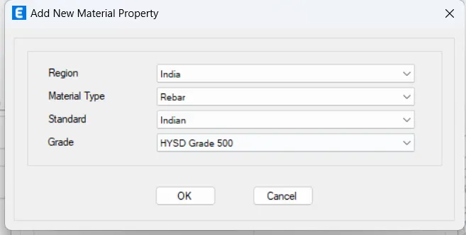
Add New Material Property dialogue box opens
Region: India
Material Type: Rebar
Standard: Indian
Grade: HYSD Grade 500
After entering the data, press OK
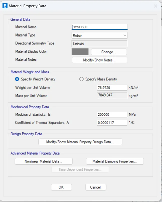
Material Property Data dialogue box opens
Press OK
Click on the Define Tab
Click on Section Properties and select Frame Sections
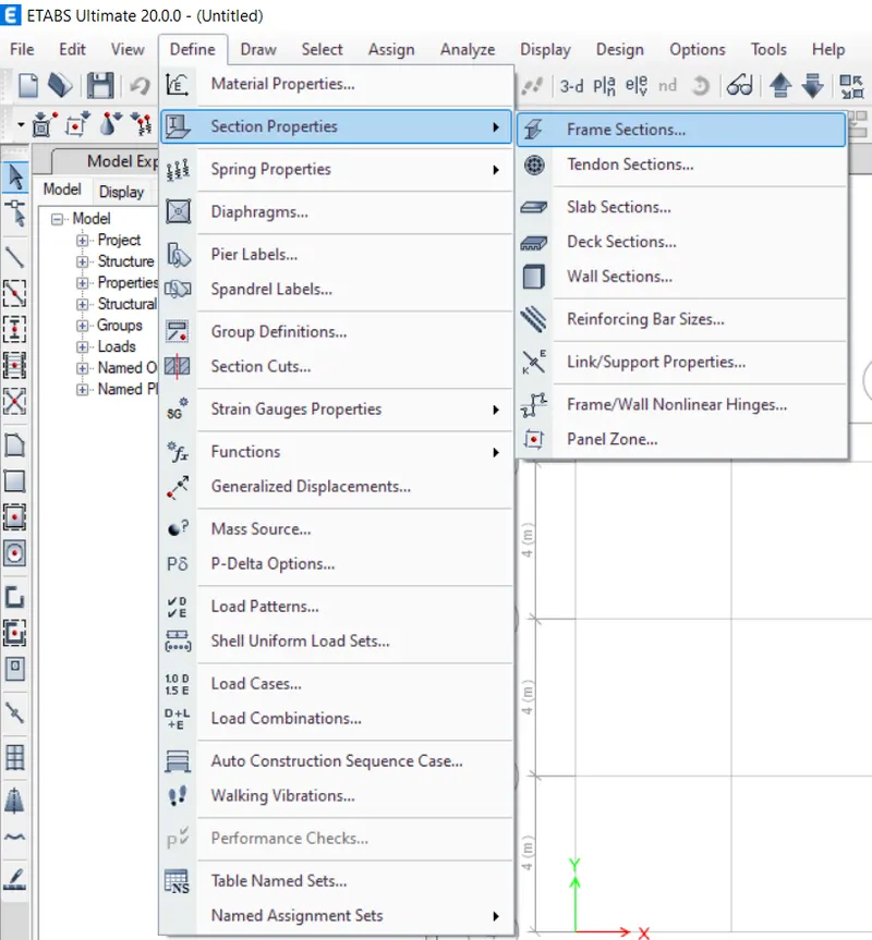
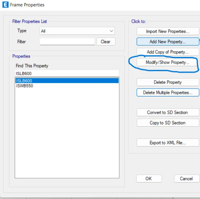
Frame Properties dialogue box opens
Click on Add New Property
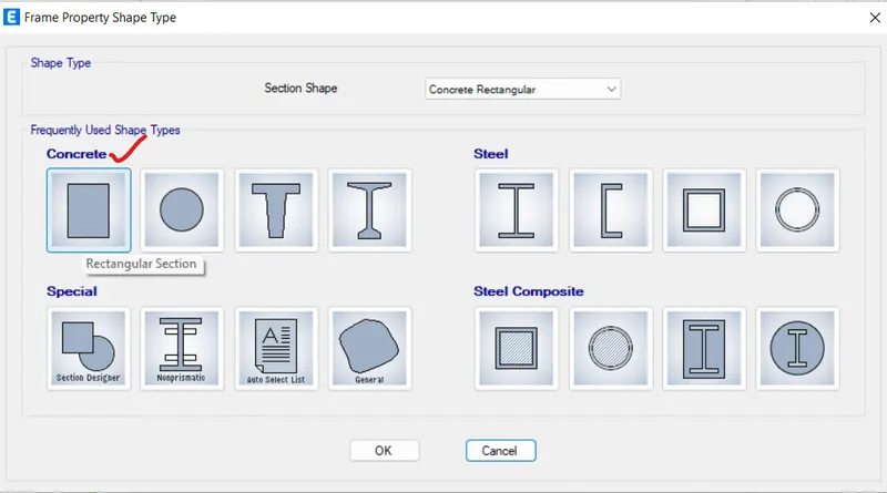
Frame Property Shape Type dialogue box opens
Section Shape: Concrete Rectangular
Click on Rectangle shape under Concrete
Frame Section Property data dialogue box opens
Enter the data
General Data
Propert Name: Column 450*600
Material: M25
Section dimensions
Width: 450mm
Depth: 600mm
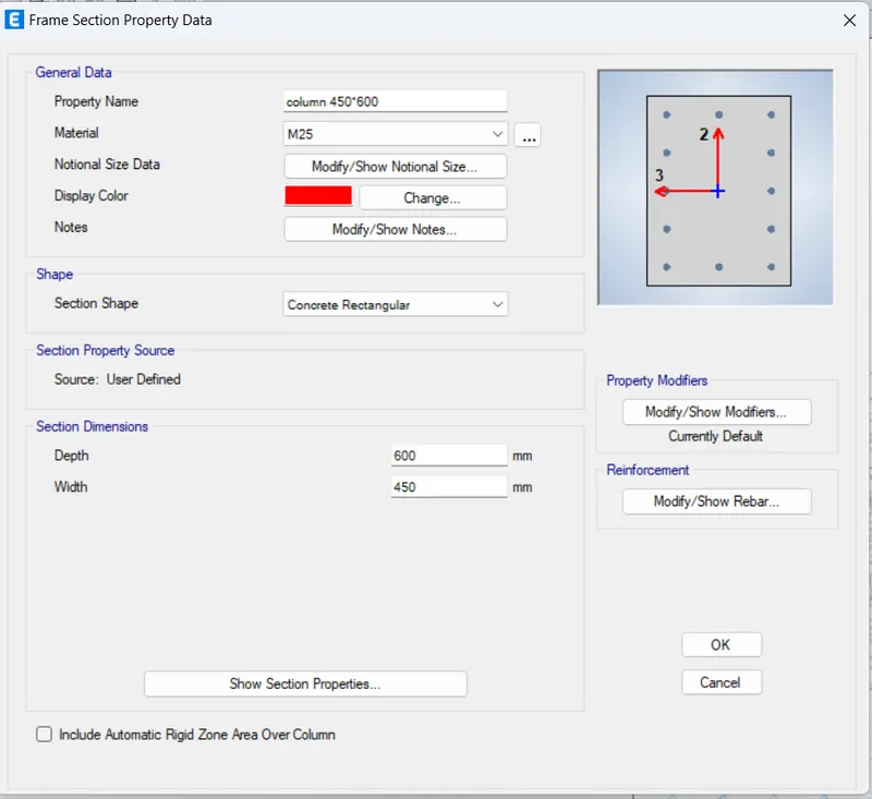
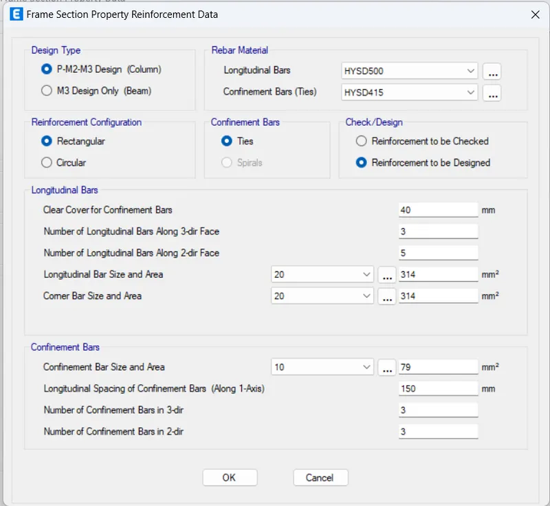
Click on Modify/Show Rebar option under Reinforcement
Frame Section Property Reinforcement data dialogue box opens
Design Type: P-M2-M3 Design(columns)
Rebar Material
HYSD500
HYSD415
Press Ok
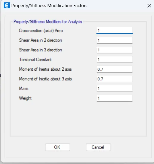
Click on Modify/Show modifiers option under Property Modifiers
Property/Stiffness modification factors dialogue box opens
Moment of Inertia about 2 axis: 0.7
Moment of Inertia about 3 axis: 0.7
Press Ok
Click on the Define Tab
Click on Section Properties and select Frame Sections
Frame Properties dialogue box opens
Click on Add New Property
Frame Property Shape Type dialogue box opens
Section Shape: Concrete Rectangular
Click on Rectangle shape under Concrete
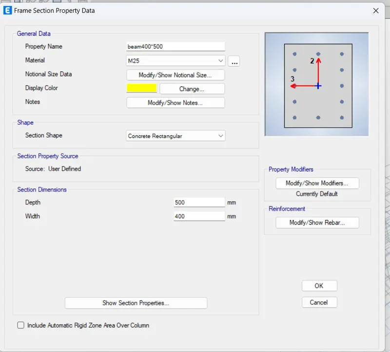
Frame Section Property data dialogue box opens
Enter the data
General Data
Propert Name: Beam 400*500
Material: M25
Section dimensions
Width: 400mm
Depth: 500mm
Click on Modify/Show modifiers option under Property Modifiers
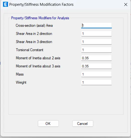
Property/Stiffness modification factors dialogue box opens
Moment of Inertia about 2 axis: 0.35
Moment of Inertia about 3 axis: 0.35
Press Ok
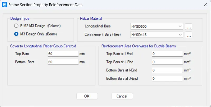
Click on Modify/Show Rebar option under Reinforcement
Frame Section Property Reinforcement data dialogue box opens
Design Type: M3 Design only(beams)
Rebar Material: HYSD415
Press Ok
Click on the Define Tab
Click on Section Properties and select Slab Sections
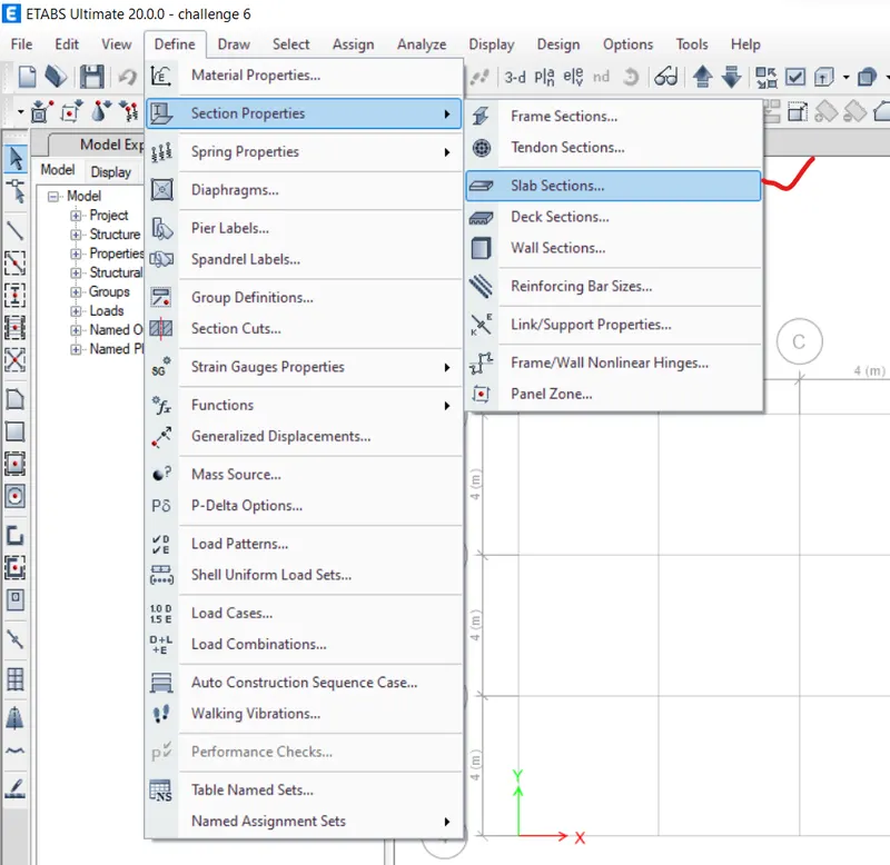
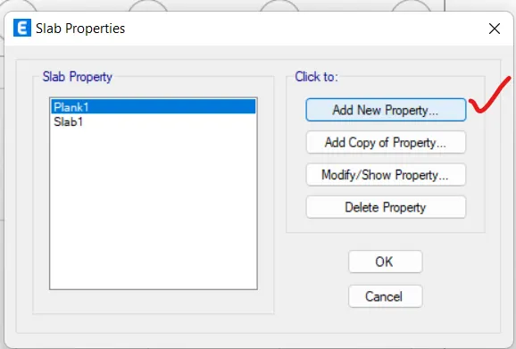
Slab Properties dialogue box opens
Click on Add New Property
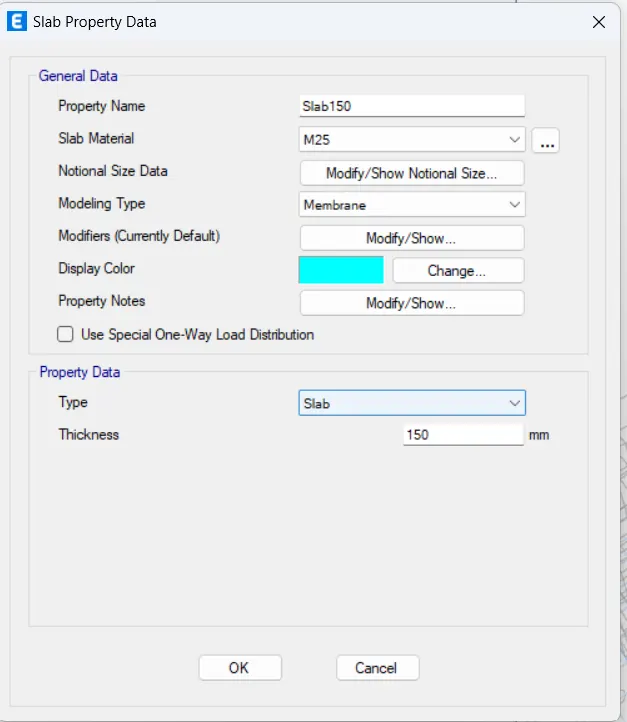
Slab Property Data dialogue box opens
General Data
Propert Name: Slab150mm
Modeling Type: membrane
Thickness: 150mm
Press Ok
Click on the Define Tab
Select Load patterns
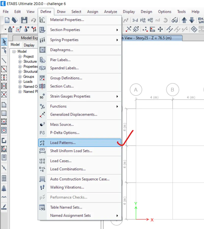
Define Load patterns dialogue box opens
Click on Add New Load option
Wall load under super dead Type
Live load under Live Type
Brick Wall under Super Dead
Floor Finish under Super dead
EQX load under Seismic Type
EQx+ load under Seismic Type
EQx- load under Seismic Type
EQY load under Seismic Type
EQy+ load under Seismic Type
EQy- load under Seismic Type
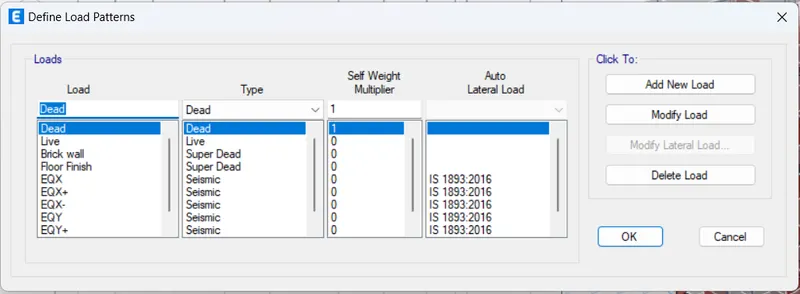
Select EQX load and click on modify lateral load option
Indian IS 1893:2016 Seismic loading dialogue box opens
Direction and Eccentricity: X dir
Seismic Co-eff: 0.36 (zone 5)
Site Type: 2
Press OK
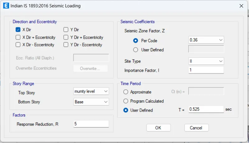
Select EQY load and click on modify lateral load option
Indian IS 1893:2016 Seismic loading dialogue box opens
Direction and Eccentricity: Y dir
Seismic Co-eff: 0.36 (zone 5)
Site Type: 2
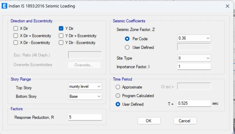
Press OK
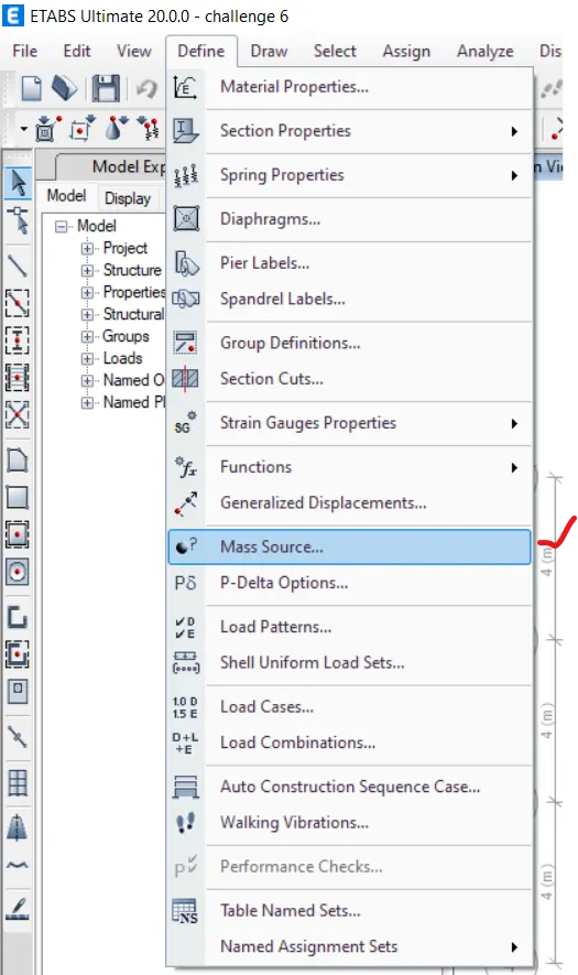
Click on the Define Tab
Select Mass Source
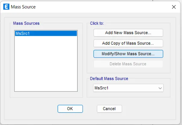
Mass Source dialogue box opens
Click on modify/show Mass Source
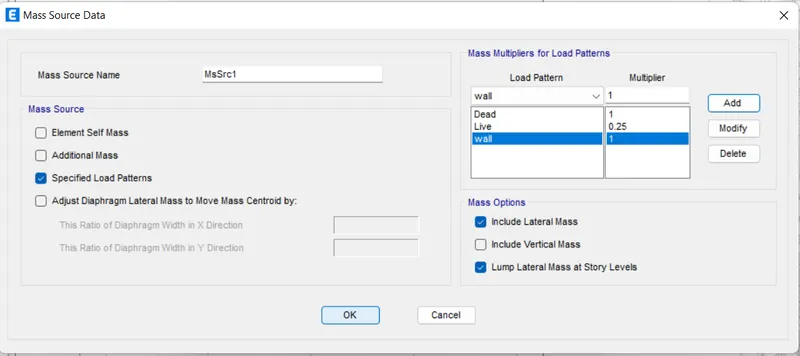
Mass Source Data dialogue box opens
Load Pattern Multiplier
Dead 1
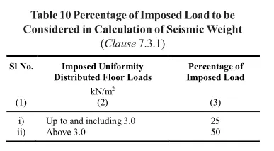
Live 0.25
Wall 1
Mass Source: Specified load patterns
Press Ok
Now, we have to create beams, columns, and slabs.
Select Quick Draw Column tool from the Draw panel
Under property browser
Property: Column 450*600
Apply the changes to All Stories
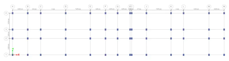
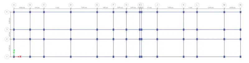
Select Quick Draw Beam/Column tool from the Draw panel
Under property browser
Property: Beam 400*500
Click on all the Grids lines.
We placed beams at all grid lines.
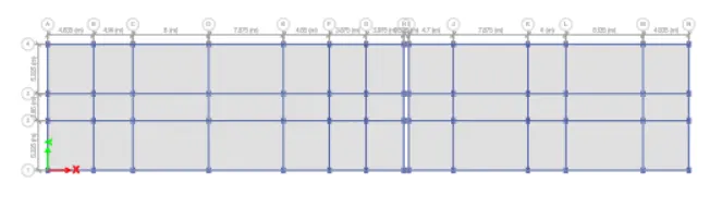
Select Quick Draw Floor/wall tool from the Draw panel
Under property browser
Property: Slab150mm
Select all the planes of the Grids
We placed slabs.
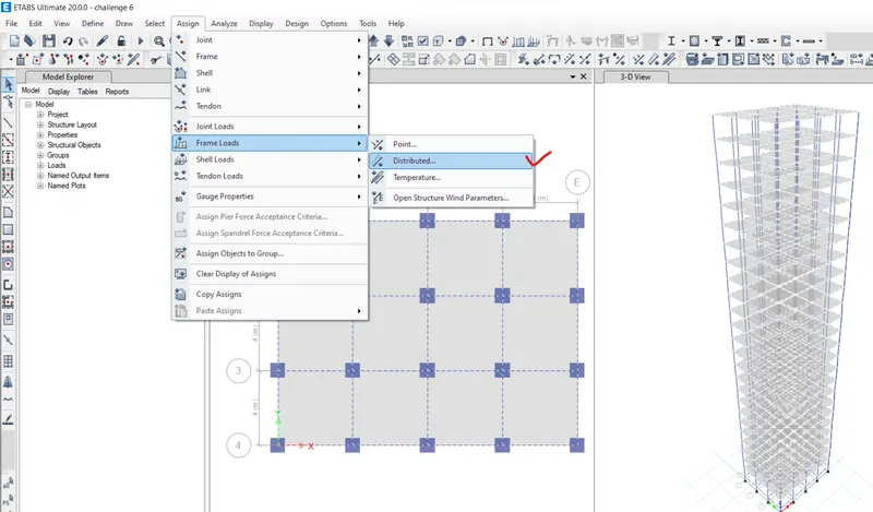
Click on Assign Tab
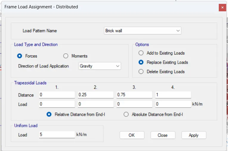
Click on Frame Loads
Select Distributed option.
Frame load Assignment-Distributed dialogue box opens
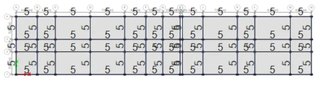
Load: 5 Kn/m
Click Apply and Press OK
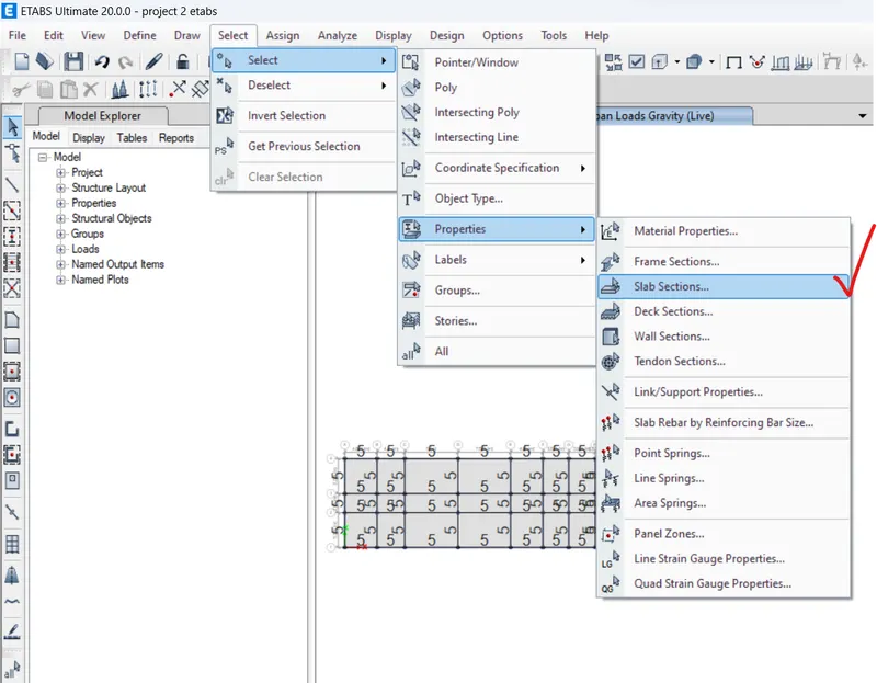
Click on Select Tab
Click on Select
Go to Properties from the list
Select Slab Sections
Select slab150mm from the list
All the slabs are selected
Click on Assign Tab
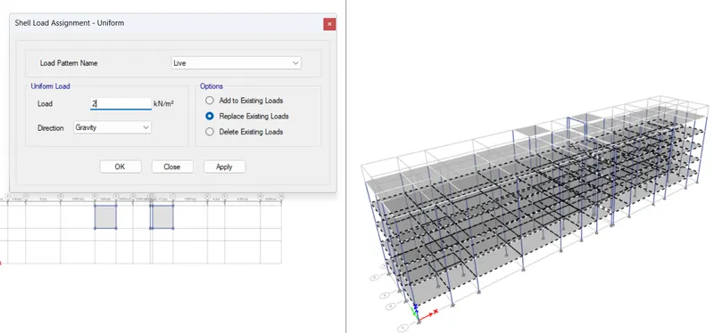
Click on shell Loads
Select Uniform option.
Shell load Assignment-Uniform dialogue box opens
Load Pattern: live load
Load: 2 kN/m
Click Apply and Press OK
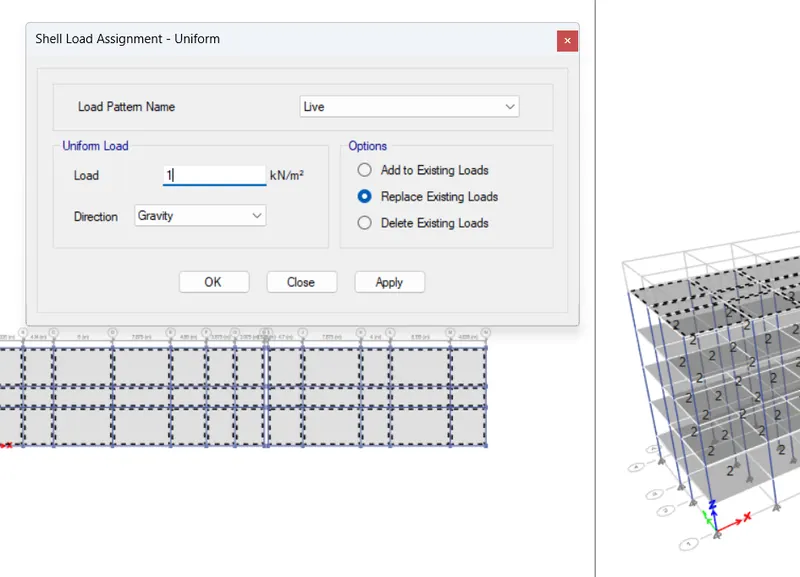
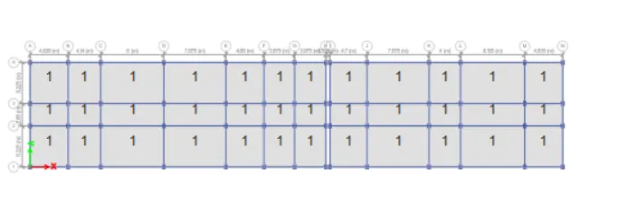
Select Roof Slabs and Mumty Slabs
Click on Assign Tab
Click on shell Loads
Select Uniform option.
Shell load Assignment-Uniform dialogue box opens
Load Pattern: live load
Load: 1 kN/m
Click Apply and Press OK
Click on Assign Tab
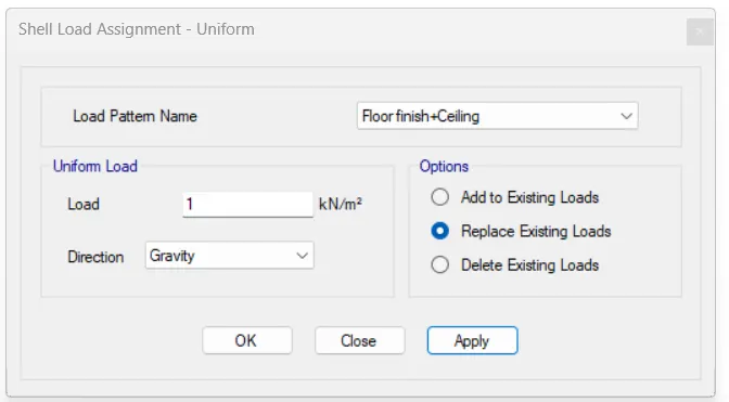
Click on shell Loads
Select Uniform option.
Shell load Assignment-Uniform dialogue box opens
Load Pattern: Floor finish
Load: 1.0 Kn/m
Click Apply and Press OK
Click on Select Tab
Click on Select
Go to Properties from the list
Select Slab Sections
Select slab150mm from the list
All the slabs are selected
Click on Assign Tab
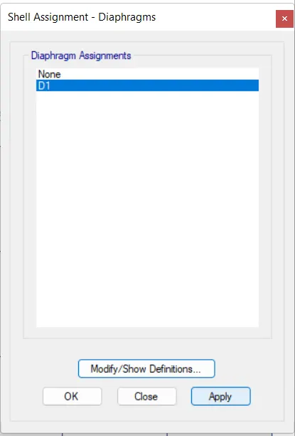
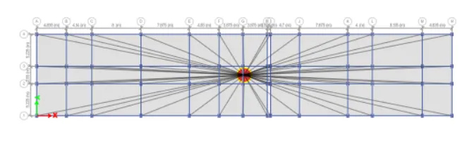
Click on shell tool
Select Diaphragms.
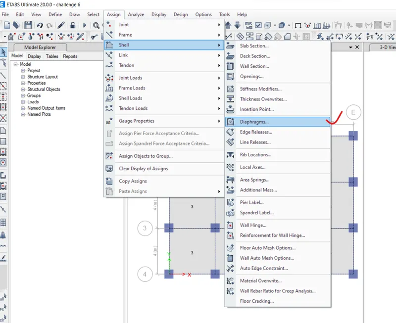
Shell Assignment- Diaphragms dialogue box opens
Select D1 in the list
Click on Apply and Press OK
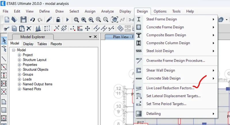
Click on DESIGN Tab
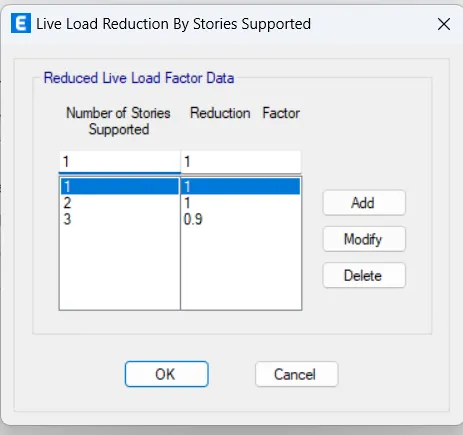
Select Live Load Reduction Factors
Live load Reduction factor dialogue box opens
Click on user defined option
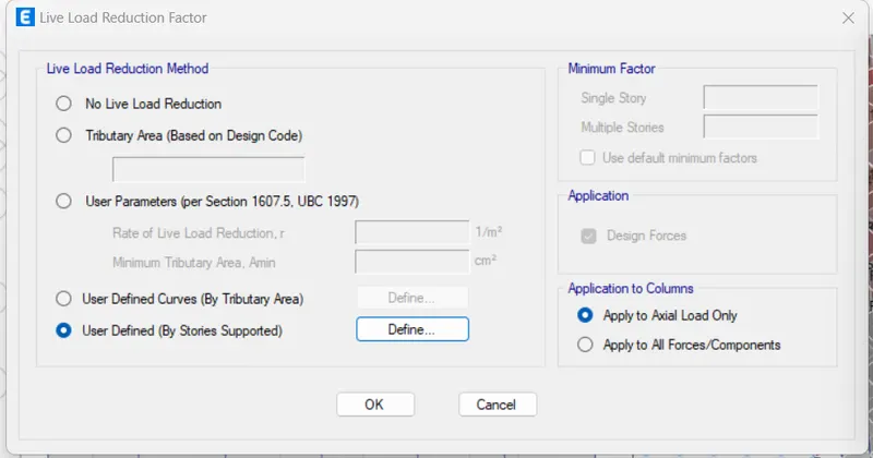
Live Load Reduction by Stories supported dialogue box opens
Enter the data as per IS 875 part 2
Press OK
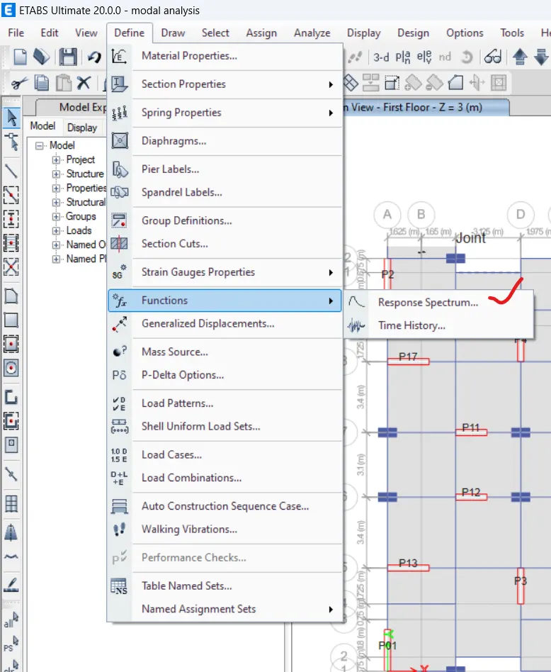
Click on DEFINE tab
Click on Functions tool
Select Response Spectrum option
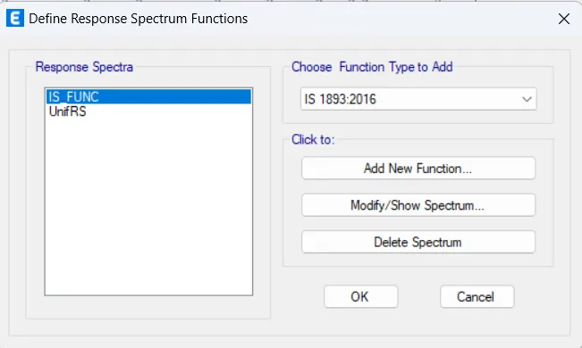
Define Response Spectrum Functions dialogue box opens
Choose Function Type: IS 1893:2016
Click to Add new Function
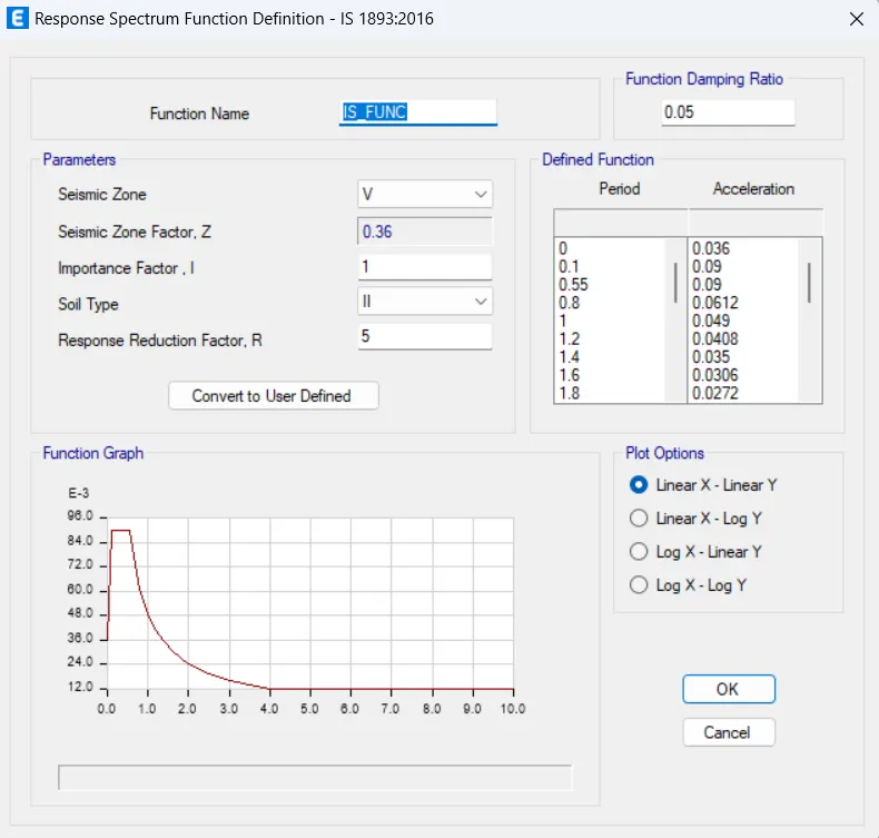
Response Spectrum Function Definition dialogue box oens
Set the data as per requirement
Press OK
Click on the Define Tab
Select Load Cases
Load Cases dialogue box opens
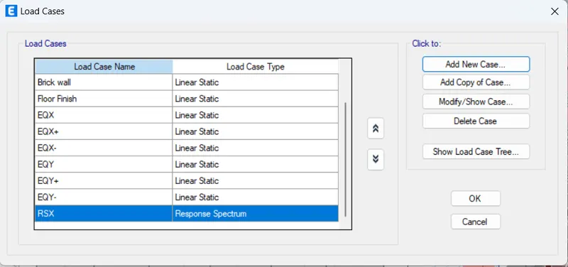
Click on Add new Case option
load case data dialogue box opens
Load case name: RSx
Load case Type: Response spectrum
massSource: Msrc1
loads Applied:
load name-U1
Function-IS_FUNC
Press OK
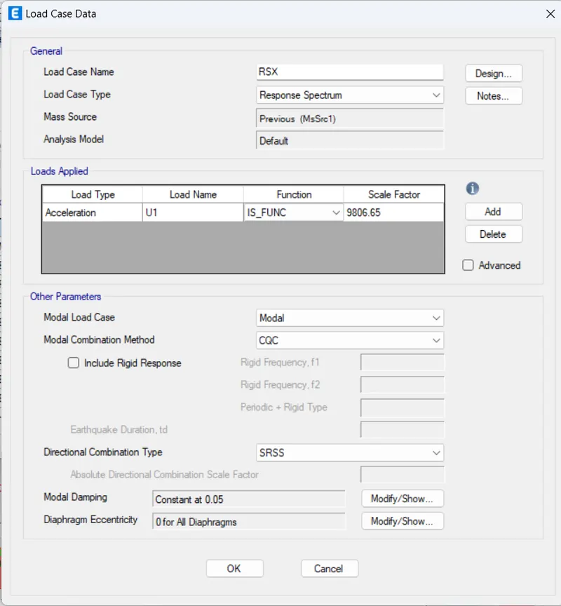
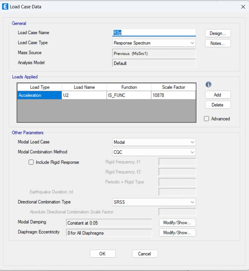
Click on Add new Case option
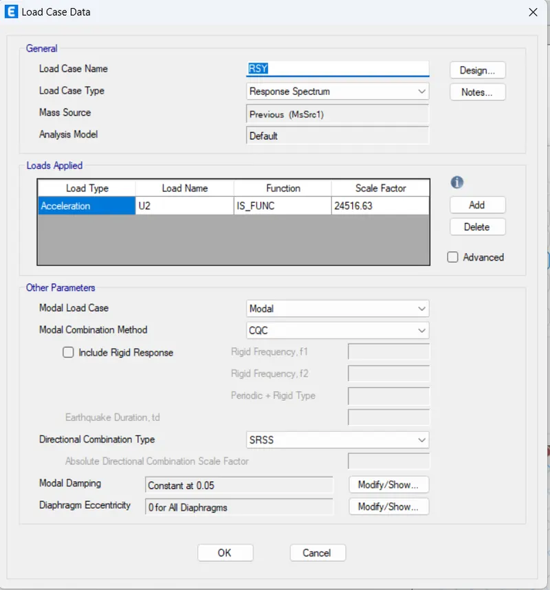
load case data dialogue box opens
Load case name: RSy
Load case Type: Response spectrum
massSource: Msrc1
loads Applied:
load name-U2
Function-IS_FUNC
Press OK
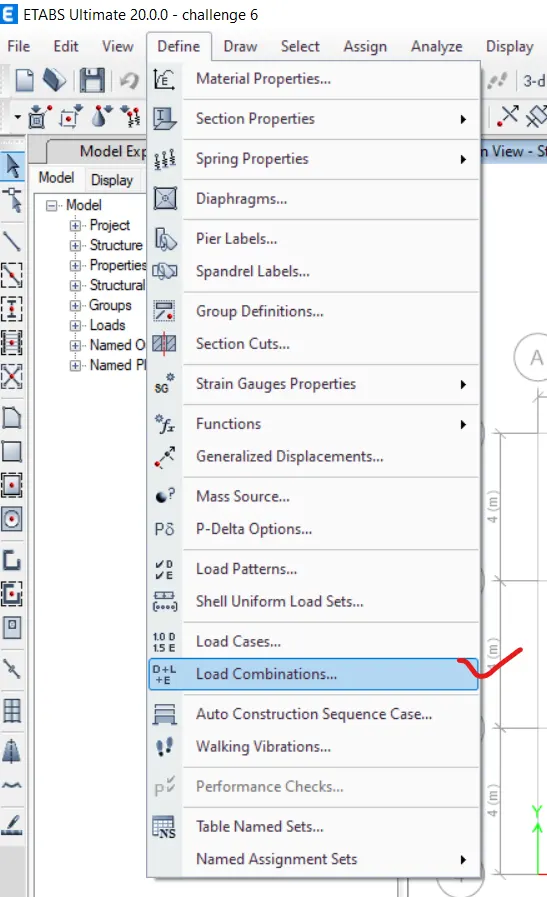
Click on the Define Tab
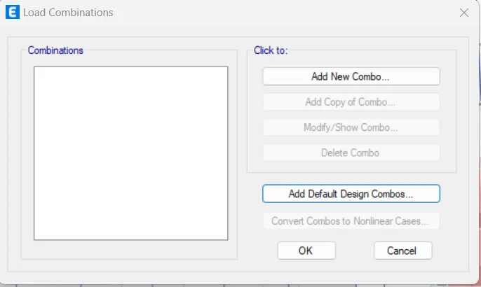
Select Load Combinations
Load Combinations dialogue box opens
Click on Add Default Design Combos
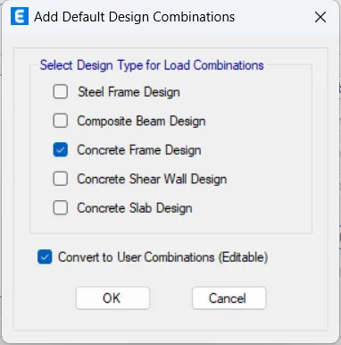
Add Default Design Combos dialogue box opens
Select Concrete Frame Design option and Concrete Shear wall design from the available list.
Press OK
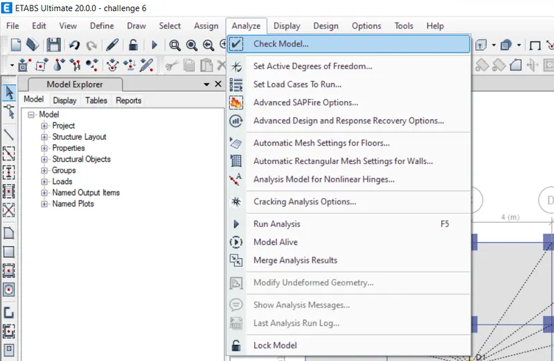
Click on Analyse Tab
Click on check Model
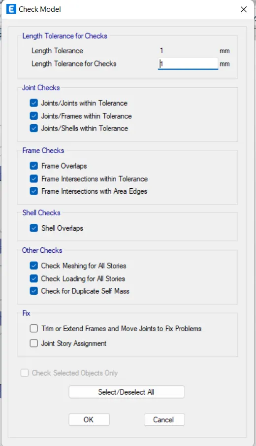
Check model dialogue box opens
Select All and press OK
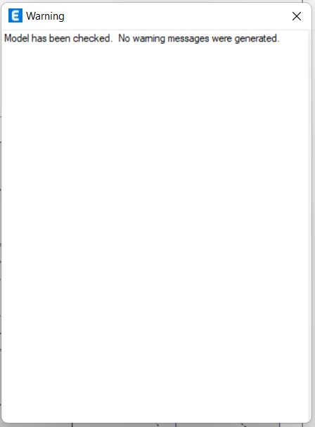
Warning dialogue box opens
No warnings have been generated.
Our model has no errors
Click on Analyse Tab
Select Run Analysis
Click DISPLAY TAB
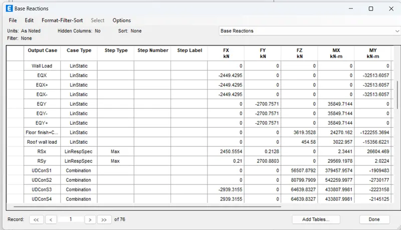
Select Show Tables
Select Base Reactions Table
DESIGN BASE SHEAR CALCULATION: -
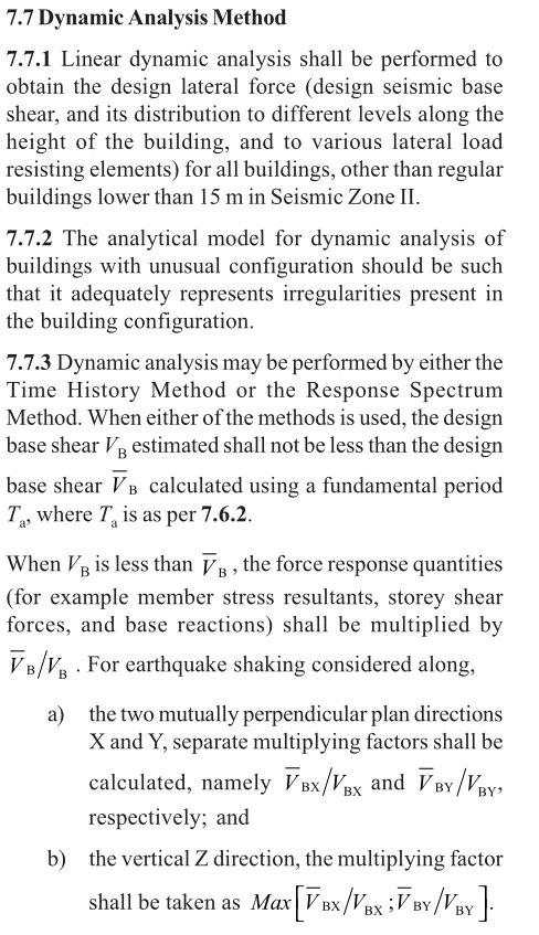
In X-Direction
From Equivalent static method Vb' = 2450kN
From Dynamic Analysis Vb = 2179 kN
Scale factor= 9806.65
Vb'/Vb = 2450/2179
= 1.12
Multiplying factor = 1.12
Scale factor in X-direction = 1.12*9806
= 11026.3
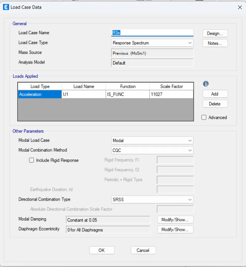
In Y-Direction
From Equivalent static method Vb' = 2700kN
From Dynamic Analysis Vb = 2434.87 kN
Scale factor= 9806.65
Vb'/Vb = 2700/2434
= 1.11
Multiplying factor = 1.11
Scale factor in Y-direction = 1.11*9806
= 10877.64
Unlock the model and
Update the scale factor in Load case data.
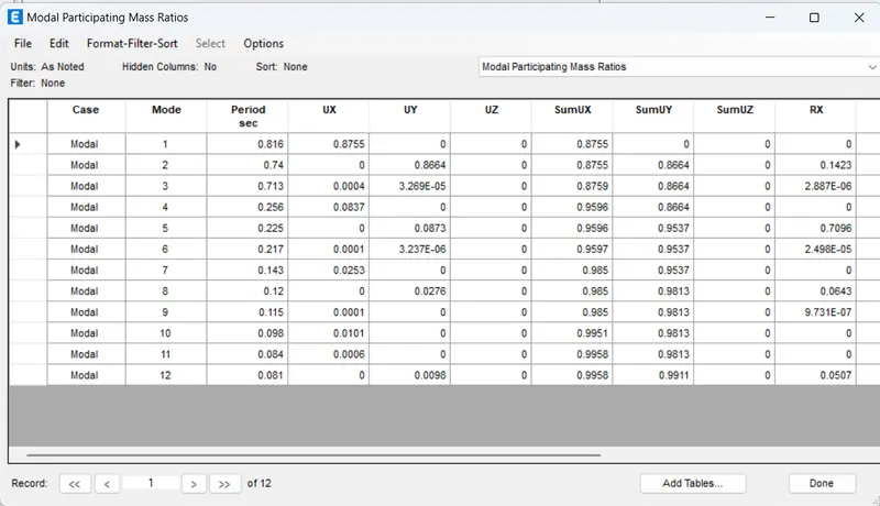
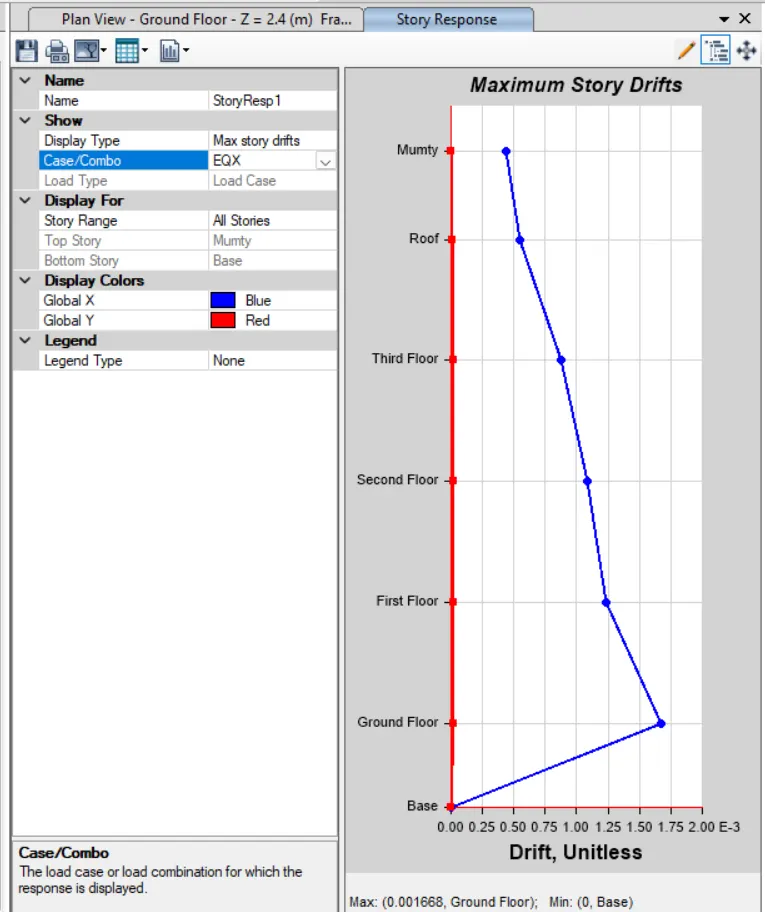
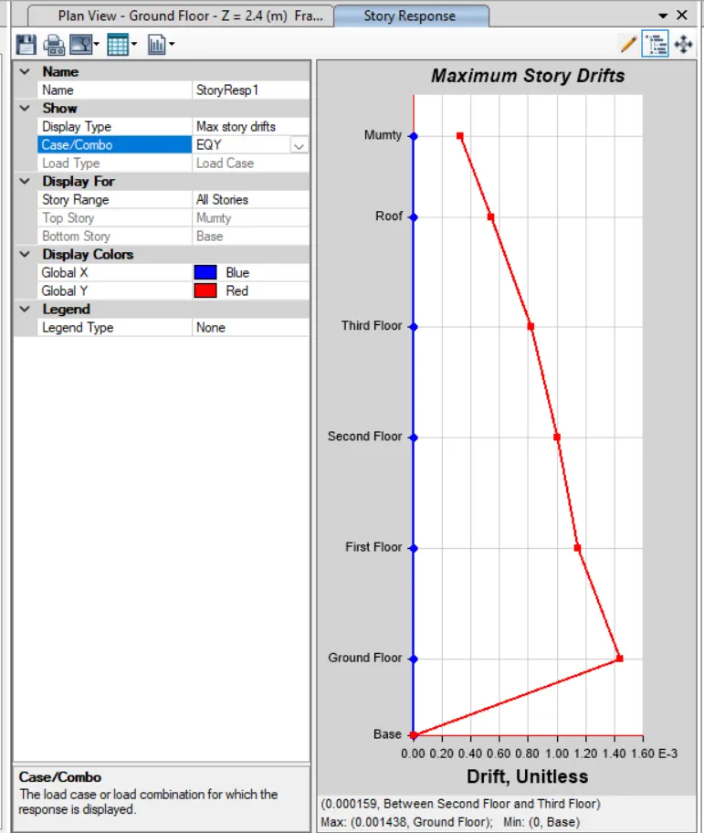
Run the Analysis once again to see the base shear reactions in dynamic analysis.
Now the dynamic base shear reactions are greater than Static base shear reactions.
Click on DESIGN TAB
Click on Concrete Frame Design
Select Design Combinations
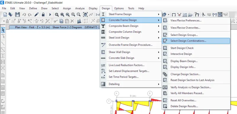
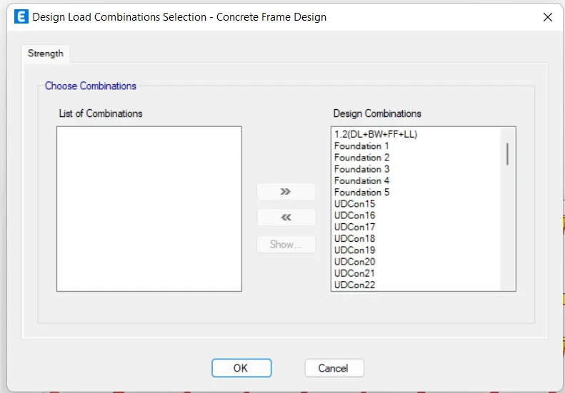
Design Load Combinations dialogue box opens
Choose the Combinations
Press OK
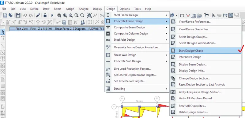
Click on DESIGN TAB
Click on Concrete Frame Design
Select Start/Design Check
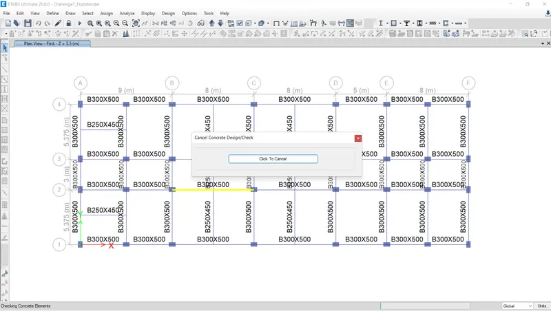
System designs the frame
Click on DESIGN TAB
Click on Concrete Frame Design
Select Display Design Info
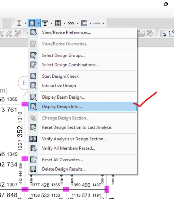
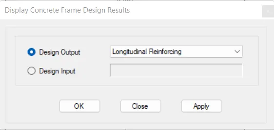
Display Concrete FrameDesign Results dialogue box opens
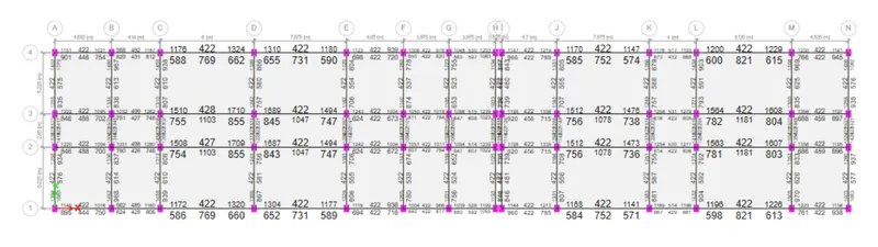
Design output: Longitudinal Reinforcing
Click on APPLY
Press OK
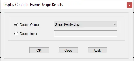
Display Concrete FrameDesign Results dialogue box opens
Design output: Shear Reinforcing
Click on APPLY
Press OK
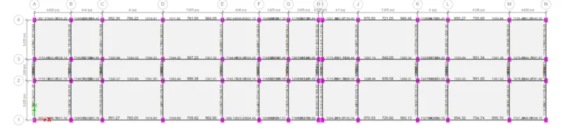
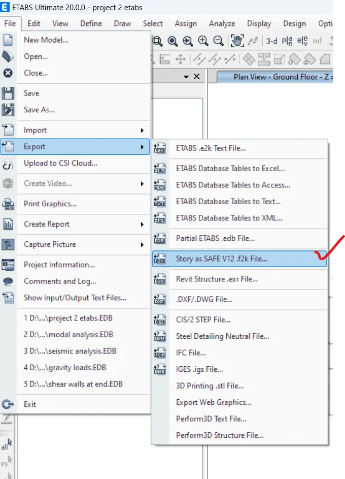
Click on File Tab > Export > Story as SAFE V12 .f2k file
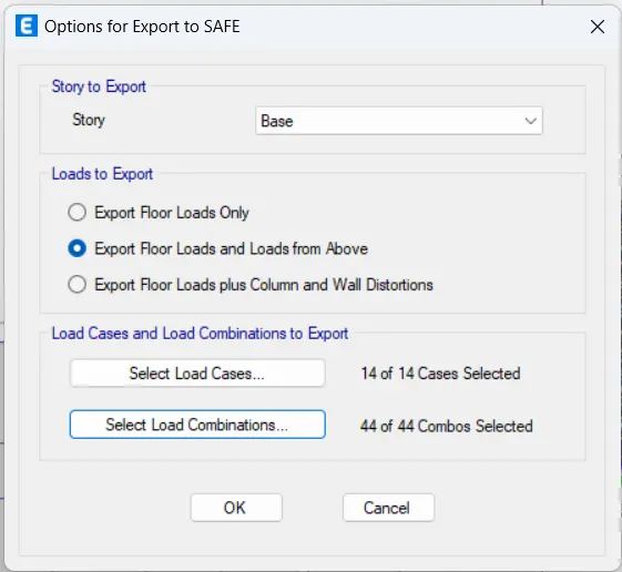
Options For Exports to Safe dialogue box opens
Story: Base
Export Floor Loads and Loads from above
Select Load cases
Select Load combinations
Press OK
Save the file to desired Loacation.
Open SAFE application
Click on New Model
Model Initialization dialogue box opens
Display Units: Metric SI
Concrete Design Code: IS 456-2000
steel design code: BS-5950
Press O.K.
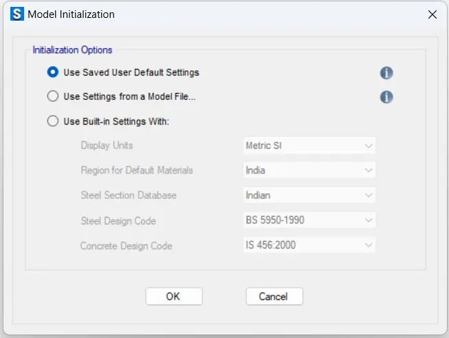
Press O.K.
Click on File Tab > Import > safe.f2k file
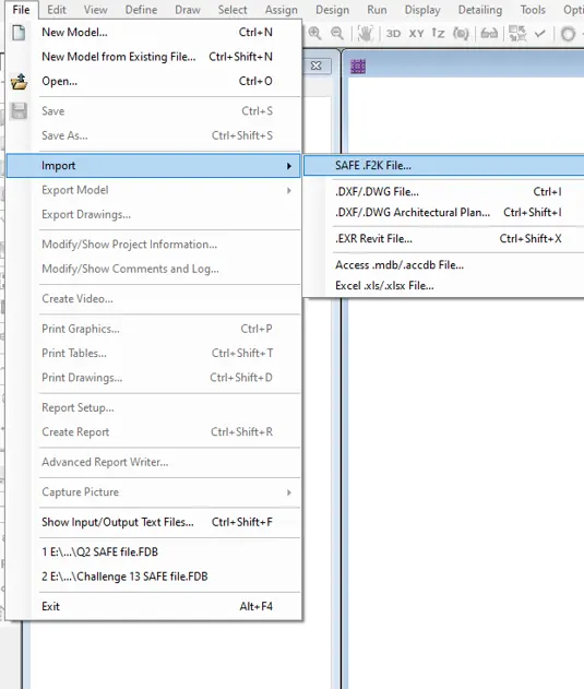
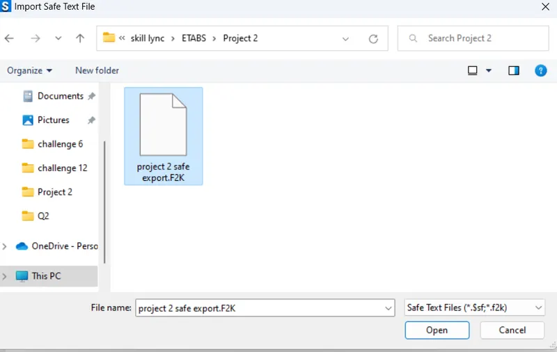
Select the file
Press open
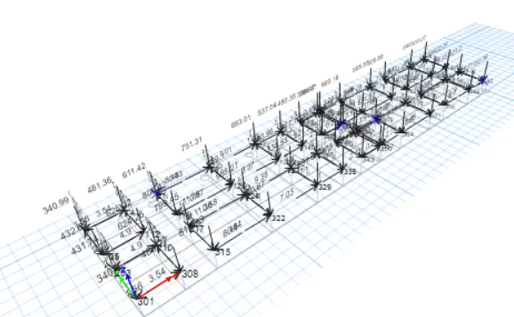
File is opened in SAFE
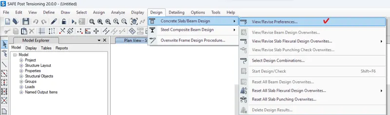
Click on DESIGN TAB
Click on concrete slab/Beam Design
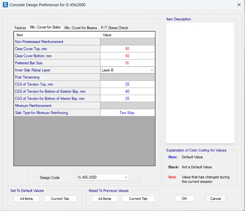
Select View/Revise Preferences option
Concrete design Preferences dialogue box opens
Change the required data
Press O.K.
Click on the Define Tab
Select Material Properties
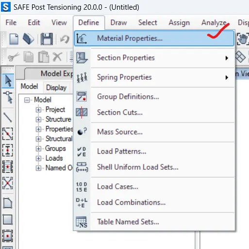
Define Materials dialogue box opens
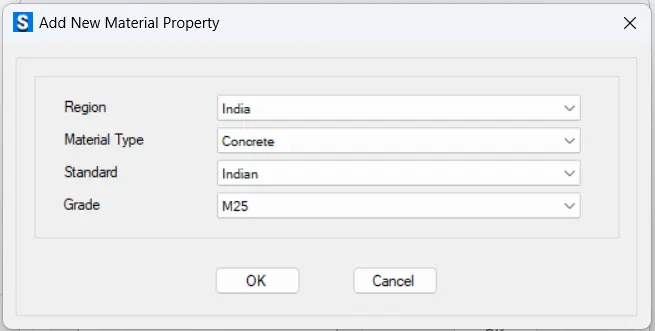
Click on Add New Material
Add New Material Property dialogue box opens
Region: India
Material Type: Concrete
Standard: Indian
Grade: M25
After entering the data, press OK
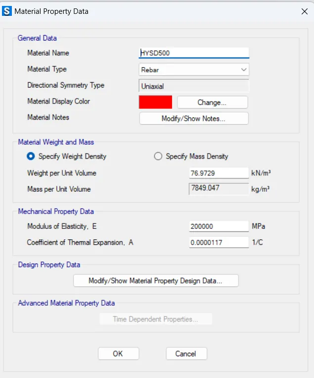
Click on Add New Material
Add New Material Property dialogue box opens
Region: India
Material Type: Rebar
Standard: Indian
Grade: HYSD Grade 500
After entering the data, press OK

Click on the Define Tab
Click on Section Properties and select Slab Sections
Slab Properties dialogue box opens
Click on Add New Property
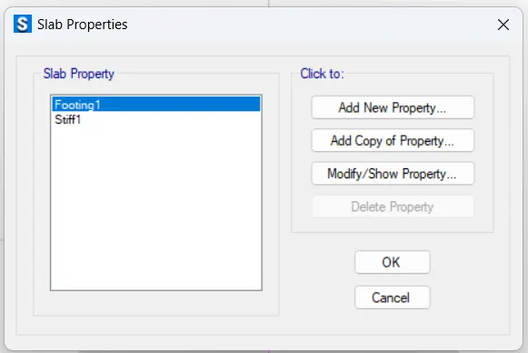
Slab property Data dialogue box opens
Propert name: Pile_cap
Slab material: M25
Type: Mat
Thickness: 1000mm
Press O.K
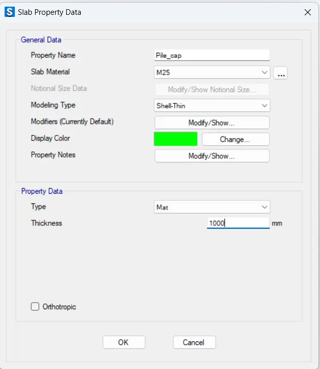
Click on Add New Property
Slab property Data dialogue box opens
Propert name: Stiff1
Slab material: M25
Type: Stiff
Thickness: 1000mm
Press O.K
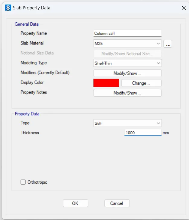
Click on Add New Property
Slab property Data dialogue box opens
Propert name: Pile_500
Slab material: M25
Type: Mat
Thickness: 1000mm
Press O.K
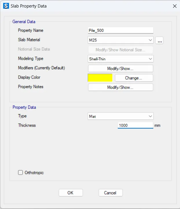
Click on DRAW TAB
Click on Draw Floor/Wall objects
Select Draw Rectangular Floor/wall tool
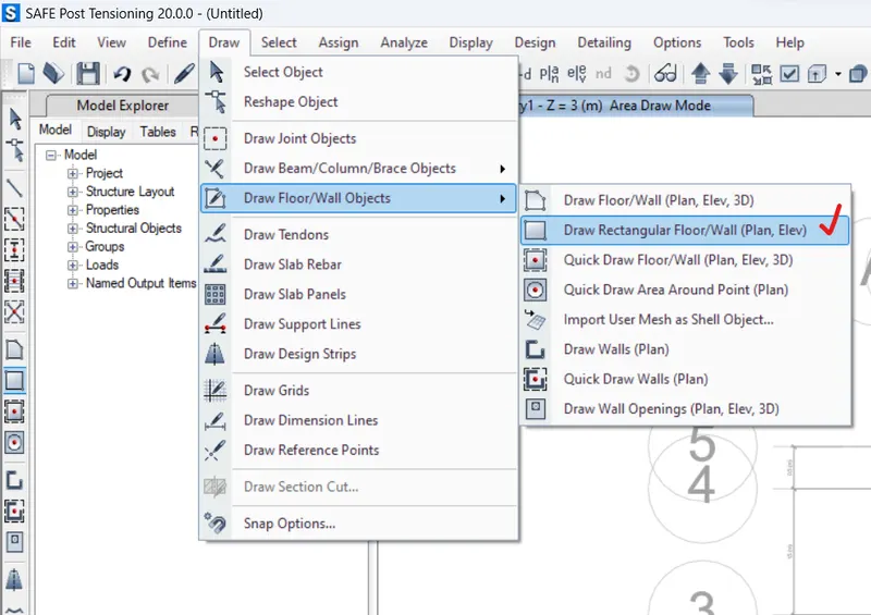
Draw Pile cap in the model screen.
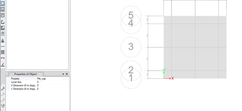
Click on DRAW TAB
Click on Draw Floor/Wall objects
Select Quick Draw Area Around Point
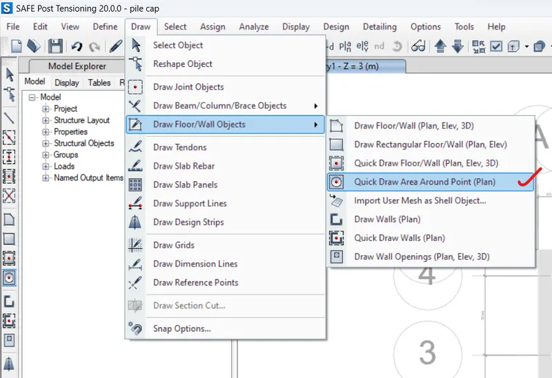
Select the data as per requirement in Properties of Object
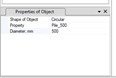
Click on DRAW TAB
Click on Draw Floor/Wall objects
Select Quick Draw Area Around Point
Click on DEFINE TAB
Click on Spring Properties > Point Springs
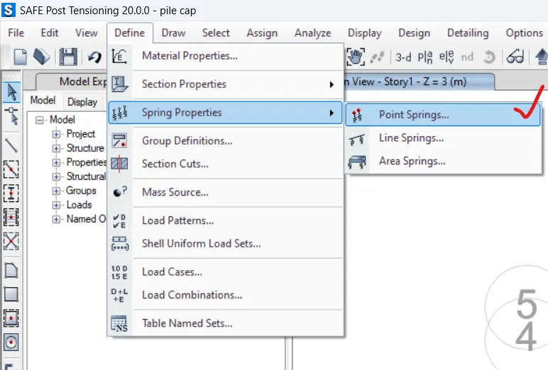
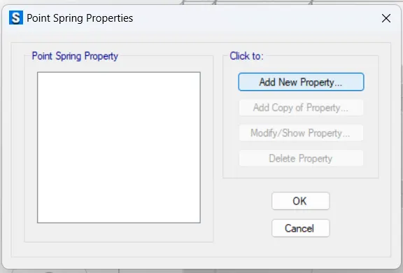
Point Spring Properties Dialogue box opens
Click on Add New Property
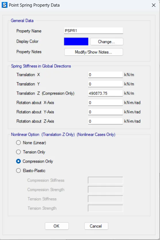
Point Spring Property Data dialogue box opens
Stiffness Spring Z: 490873.75 kN/m
Compression only
Press OK
Click on SELECT TAB
Click on Select > Properties > Slab Section
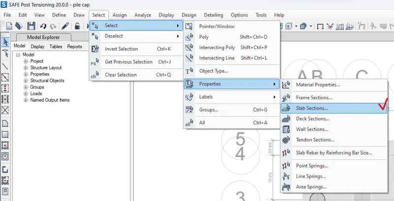
Select by Slab Property dialogue box opens
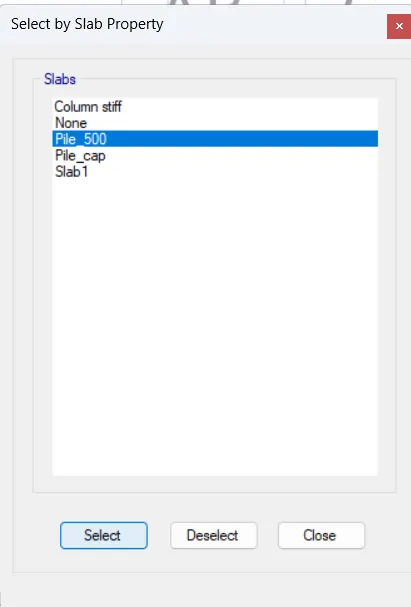
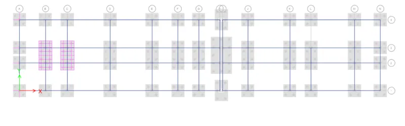
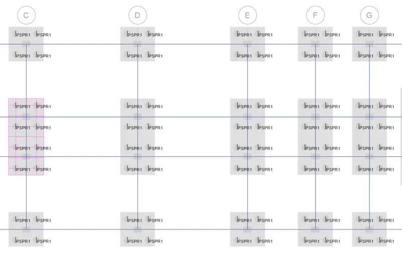
Assign Spring Properties to Piles
Click on ASSIGN TAB
Click on Joint > Springs
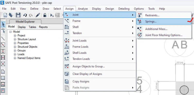
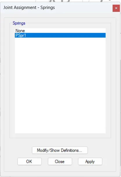
Joint Assignment Spring dialogue box opens
Select the Spring
Click on Apply
Press OK
Click on DEFINE TAB
Click on Load Cases
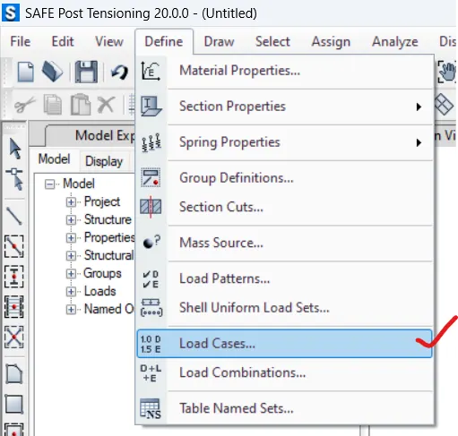
Load Cases dialogue box opens
Check all the loads
Press OK
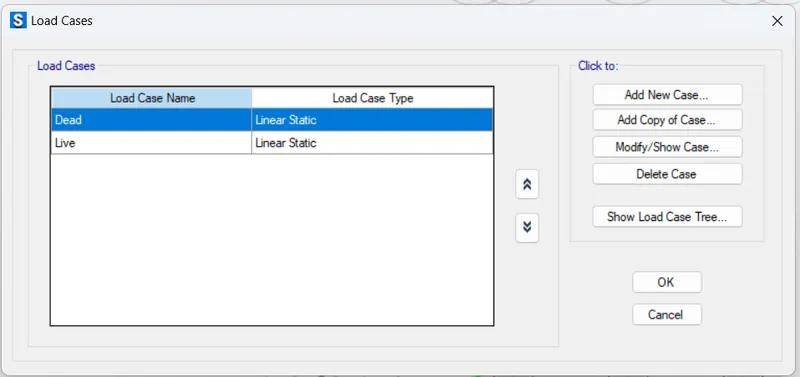
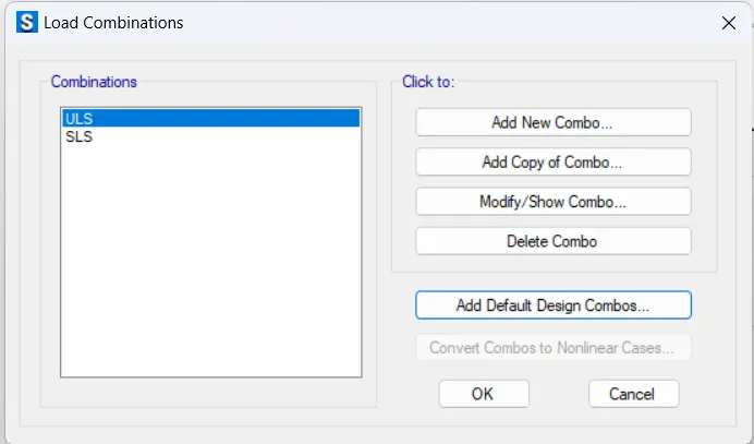
Click on DEFINE TAB
Select Load Combinations
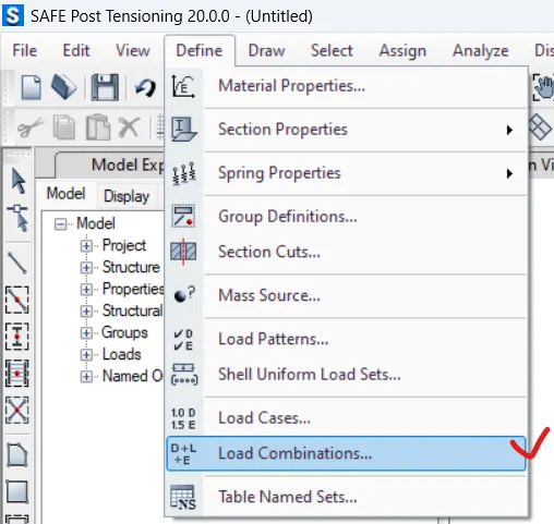
Load Combinations dialogue box opens
Add New Combo
Press OK
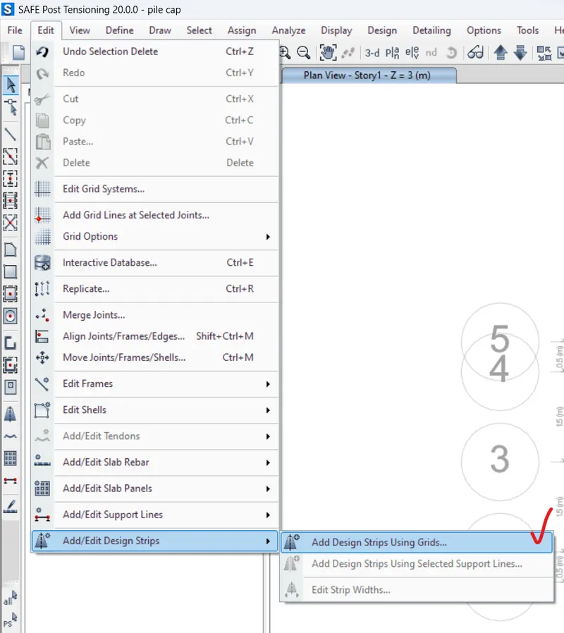
Click on EDIT TAB
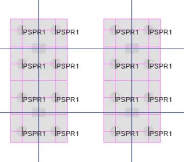
Click on Add/edit Design Strips > Add design Strips using Grids
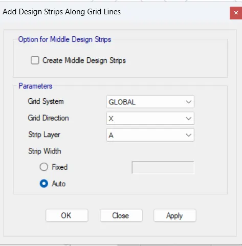
Add Design Strips Along Grid Lines dialgue box opens
Grid direction: X
Strip layer: A
Click on Apply
Press OK
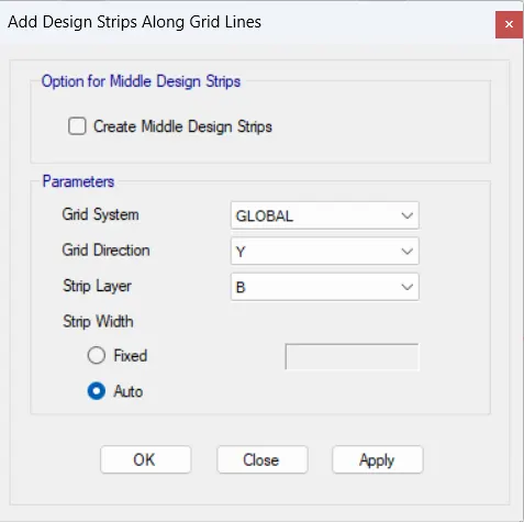
Grid direction: Y
Strip layer: B
Click on Apply
Press OK
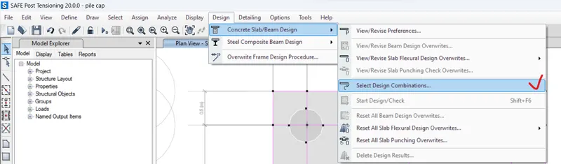
Click on DESIGN TAB
Select Design Combinations
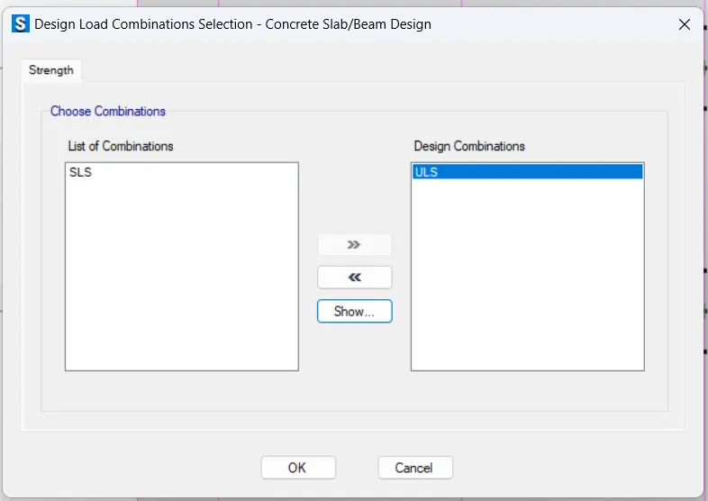
Design Load Combinations Selection dialogue box opens
Select the Design combinations
Press OK
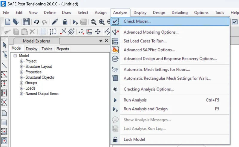
Click on ANALYSE TAB
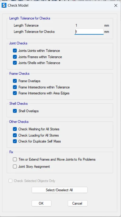
Select Check Model
Check Model dialogue box opens
Select all
Press Ok
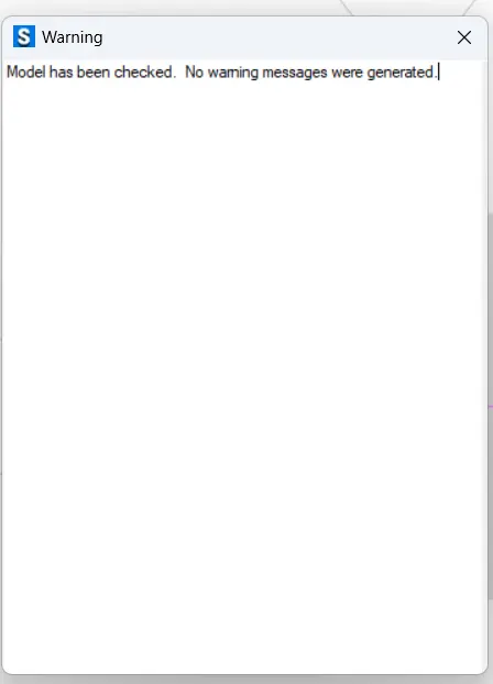
No warnings message were generated.
Click on ANALYSE TAB
Run the Analysis
RESULT: -
1. Modelled, analyzed, designed the given building.
2. Produced the results of the following:
- Tie Beam connecting Pile Caps
Tie beam details connecting the pile caps
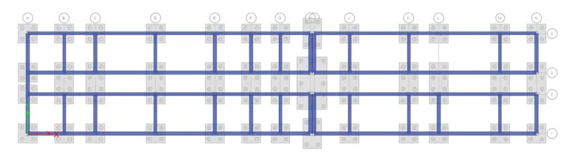
- Foundation details illustrating the pile & pile cap reinforcement
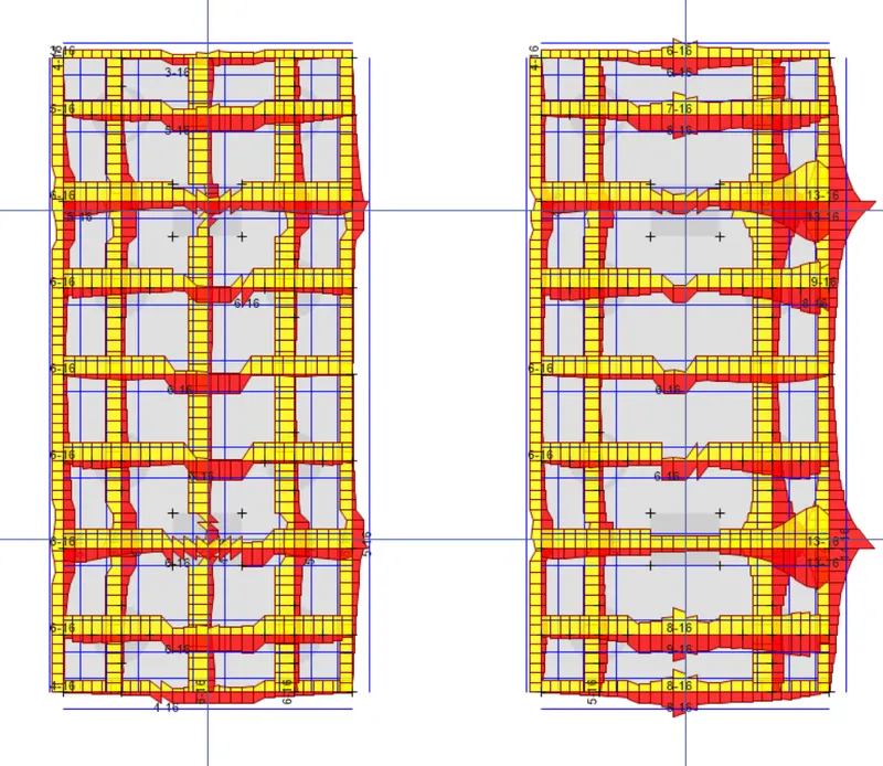
Strip Forces
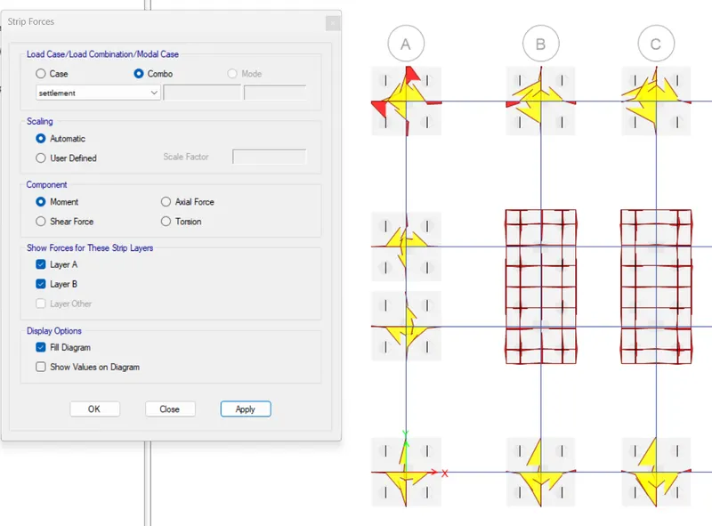
Flexural Reinforcement design of Plie Footing
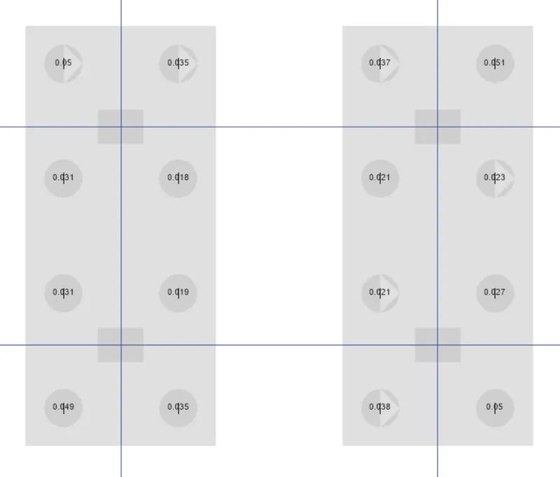
Two Way Shear Ratio
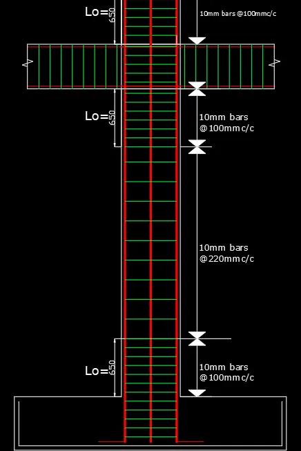
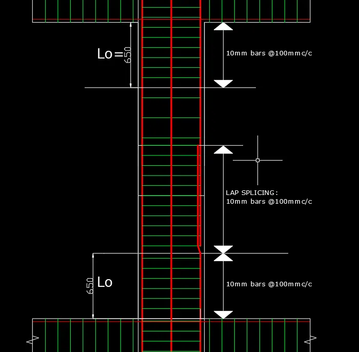
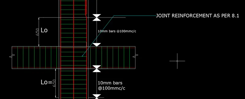
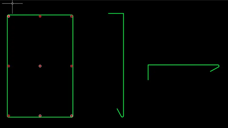
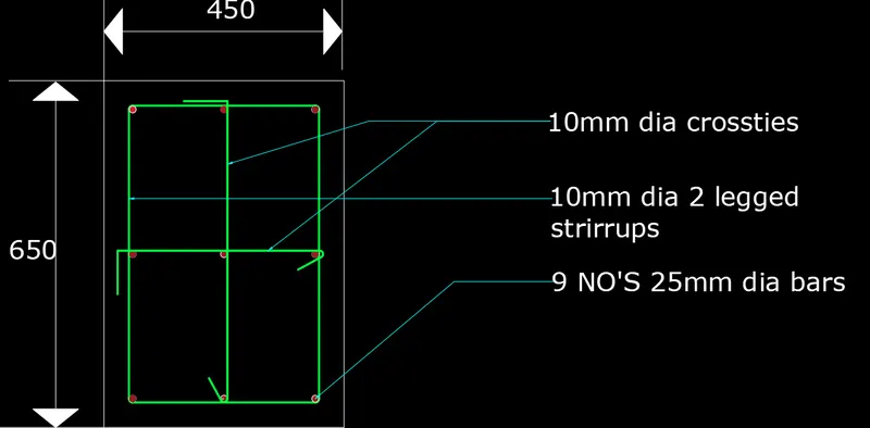
- Reinforcement Details of Column
Column reinforcement
- BEAM REINFORCEMENT DETAILS
Beam reinforcements for ground floor