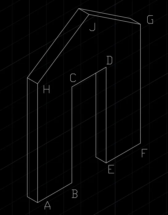
Creating a Floor plan, Footing detail and Isometric view using AutoCad
1Q]
AIM: -
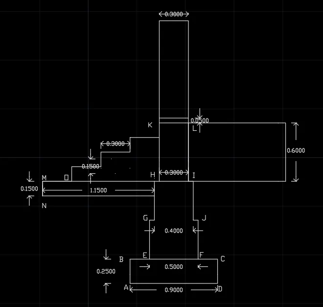
Draw cross section of Load Bearing Wall over spread footing
PROCEDURE: -
Turn on ORTHO command on
Select line tool.
Specify 1st point: A (1,1)
Position the cursor to the up direction (making angle of 90 degrees) from previous point and specify the distance 0.25 units. Mark as B
Position the cursor to the right (making angle of zero degrees) from previous point and specify the distance 0.9 units. Mark as C
Position the cursor to the down direction (making angle of 90 degrees) from previous point and specify the distance 0.25 units. Mark as D
Close to A
Select OFFSET tool
Specify offset distance as 0.2 units.
Select the object line AB and specify point on right side to offset.
AB offset line touches line BC. Mark point as E
Select the object line CD and specify point on left side to offset.
CD offset line touches line BC. Mark point as F
Select line tool
Specify 1st point as E
Position the cursor to the up direction (making angle of 90 degrees) from previous point and specify the distance 0.4 units. Mark point as G
Position the cursor to the right (making angle of zero degrees) from previous point and specify the distance 0.05 units.
Position the cursor to the up direction (making angle of 90 degrees) from previous point and specify the distance 0.4 units. Mark point as H
Position the cursor to the right (making angle of zero degrees) from previous point and specify the distance 0.4 units. Mark point as I
Position the cursor to the down direction (making angle of 90 degrees) from previous point and specify the distance 0.4 units.
Position the cursor to the right (making angle of zero degrees) from previous point and specify the distance 0.05 units. Mark point as J
Position the cursor to the down direction (making angle of 90 degrees) from previous point and specify the distance 0.4 units. This should coincide with point F.
Erase offset lines of AB & CD
Choose Line tool
Select point H and position the cursor to the right (making angle of zero degrees) from previous point and specify the distance 0.05 units.
Position the cursor to the up direction (making angle of 90 degrees) from previous point and specify the distance 0.6 units. Mark point as K
Position the cursor to the right (making angle of zero degrees) from previous point and specify the distance 0.3 units. Mark point as L
Position the cursor to the down direction (making angle of 90 degrees) from previous point and specify the distance 0.6 units. and click exit.
Select RECTANGLE tool and specify the 1st point as L
Select dimensions option and provide length as 1 units and width as 0.6 units
Position the cursor below to the point L. and draw Rectangle.
Select Line tool and specify 1st point as K and
position the cursor to the up direction (making angle of 90 degrees) from previous point and specify the distance 1.05 units.
Position the cursor to the right (making angle of zero degrees) from previous point and specify the distance 0.3 units.
Position the cursor to the down direction (making angle of 90 degrees) from previous point and specify the distance 1.05 units. and click exit.
Select OFFSET tool
Specify offset distance: 0.05 units.
Select object a line KL
Specify point on above the line KL to offset 0.05 units.
Choose line tool and specify 1st point as H
Position the cursor to the left (making angle of zero degrees) from previous point and specify the distance 1.15 units. Mark point as M
position the cursor to the down direction (making angle of 90 degrees) from previous point and specify the distance 0.15 units.
Position the cursor to the right (making angle of zero degrees) from previous point and specify the distance 1.15 units. and click exit.
Choose line tool and specify 1st point as M
Position the cursor to the right (making angle of zero degrees) from previous point and specify the distance 0.3 units. and click exit. Mark point as O
Select COPY tool
Select objects as MN & MO
Select base point as N and place the point N on above the point O
Repeat the process for 3 times such that top end point O has touch the line KH and click exit.
RESULT: -
2Q]
AIM: -
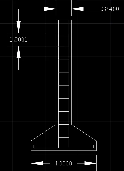
Create cross section of Isolated Footing
PROCEDURE: -
Turn on ORTHO command
Select Line tool
Specify 1st point: A (1,1)
Specify next point: Position the cursor to the up direction (making angle of 90 degrees) from previous point and specify the distance 0.15 units. Mark as B
Specify next point: C (@0.38,0.25)
Specify next point: Position the cursor to the up direction (making angle of 90 degrees) from previous point and specify the distance 1.6 units. Mark as D
Specify next point: Position the cursor to the right (making angle of zero degrees) from previous point and specify the distance 0.24 units. Mark as E
Specify next point: Position the cursor to the down direction (making angle of 90 degrees) from previous point and specify the distance 1.6 units. Mark as F
Specify next point: G (@0.38, -0.25)
Specify next point: Position the cursor to the down direction (making angle of 90 degrees) from previous point and specify the distance 0.15 units. Mark as H
Close to A
To draw main reinforcement
Select OFFSET tool
Specify offset distance as 0.04 units
Select object as line CD and Specify point on right of CD side to offset 0.04 units
Select object as line EF and Specify point on LEFT of EF side to offset 0.04 units
Select object as line AH and Specify point on TOP of AH side to offset 0.04 units
Stretch the newly drawn offset lines CD & EF till they intersect the AH offset line.
Erase the AH offset line.
Select line tool
Specify 1st point as bottom of CD offset line and position the cursor to the left (making angle of zero degrees) from previous point and specify the distance 0.38 units.
Position the cursor to the up direction (making angle of 90 degrees) from previous point and specify the distance 0.05 units. and click exit.
Select line tool
Specify 1st point as bottom of EF offset line and position the cursor to the right (making angle of zero degrees) from previous point and specify the distance 0.38 units.
Position the cursor to the up direction (making angle of 90 degrees) from previous point and specify the distance 0.05 units. and click exit.
To draw distribution steel or ties
Join offset lines of CD and EF at top using Line command.
Select COPY command
Select object as newly drawn line and press enter.
Specify base point and select ARRAY option
Enter no of items to array: 10
Specify 2nd point as 0.2 units.
Click exit
RESULT: -
Cross Section of Isolated Footing
3Q]
AIM: -
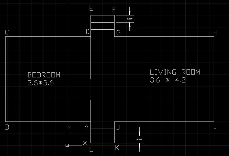
Create a Line Diagram of a Two Bedroom Building
PROCEDURE: -
Turn on the ORTHO command tool.
Select Line tool
Specify 1st point: A (1,1)
Position the cursor to the left direction (making angle of zero degrees) from point A and specify the distance 3.6 units. Mark as point B
Position the cursor to the up direction (making angle of 90 degrees) from previous point and specify the distance 3.6 units. Mark as C
Position the cursor to the right (making angle of zero degrees) from previous point and specify the distance 3.6 units. Mark as D
Position the cursor to the up direction (making angle of 90 degrees) from previous point and specify the distance 0.9 units. Mark as E
Position the cursor to the right (making angle of zero degrees) from previous point and specify the distance 1 units. Mark as F
Position the cursor to the down direction (making angle of 90 degrees) from previous point and specify the distance 0.9 units. Mark as G
Position the cursor to the right (making angle of zero degrees) from previous point and specify the distance 4.2 units. Mark as H
Position the cursor to the down direction (making angle of 90 degrees) from previous point and specify the distance 3.6 units. Mark as I
Position the cursor to the left direction (making angle of zero degrees) from point A and specify the distance 3.6 units. Mark as point J
Position the cursor to the down direction (making angle of 90 degrees) from previous point and specify the distance 0.9 units. Mark as K
Position the cursor to the left (making angle of zero degrees) from previous point and specify the distance 1 units. Mark as L
Close to A
Select Line tool
Select point A and draw line positioning the cursor to the up direction (making angle of 90 degrees) from previous point and specify the distance 0.9 units.
Select point D and draw line positioning the cursor to the down direction (making angle of 90 degrees) from previous point and specify the distance 1.8 units.
Choose OFFSET tool
Specify offset distance 0.3 units
Select object as line EF and select multiple option
Specify point on side to offset (below line EF) and draw 2 lines one below the other with offset of 0.3 units
Choose OFFSET tool
Specify offset distance 0.3 units
Select object as line LK and select multiple option
Specify point on side to offset (above line LK) and draw 2 lines one above the other with offset of 0.3 units
RESULT: -
4Q]
AIM: -
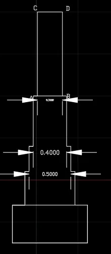
Create cross section of Load Bearing Wall
PROCEDURE: -
Select Rectangle tool
Specify 1st corner point: A (1,1)
Select Dimensions
Specify length of Rectangle: 0.3 units
Specify width of Rectangle: 1.0 units.
Specify other corner point on the display to give direction to Rectangle.
Rectangle “ABCD” is formed.
Turn on the ORTHO command
Choose Polyline tool and select point A.
Position the cursor to the left (making angle of zero degrees) from point A and specify the distance 0.05 units
Position the cursor to the down (making angle of 90 degrees) from previous point and specify the distance 0.6 units
Position the cursor to the left (making angle of zero degrees) from previous point and specify the distance 0.05 units
Position the cursor to the down (making angle of 90 degrees) from previous point and specify the distance 0.3 units
Position the cursor to the left (making angle of zero degrees) from previous point and specify the distance 0.05 units
Position the cursor to the down (making angle of 90 degrees) from previous point and specify the distance 0.4 units
Position the cursor to the left (making angle of zero degrees) from previous point and specify the distance 0.15 units
Position the cursor to the down (making angle of 90 degrees) from previous point and specify the distance 0.45 units
Position the cursor to the Right (making angle of zero degrees) from previous point and specify the distance 0.9 units
Position the cursor to the up (making angle of 90 degrees) from previous point and specify the distance 0.45 units
Position the cursor to the left (making angle of zero degrees) from previous point and specify the distance 0.9 units and select exit..
Choose Polyline tool and select point B
Position the cursor to the Right (making angle of zero degrees) from point B and specify the distance 0.05 units
Position the cursor to the down (making angle of 90 degrees) from previous point and specify the distance 0.6 units
Position the cursor to the right (making angle of zero degrees) from previous point and specify the distance 0.05 units
Position the cursor to the down (making angle of 90 degrees) from previous point and specify the distance 0.3 units
Position the cursor to the right (making angle of zero degrees) from previous point and specify the distance 0.05 units
Position the cursor to the down (making angle of 90 degrees) from previous point and specify the distance 0.4 units and select exit.
RESUILT: -
5Q]
AIM: -
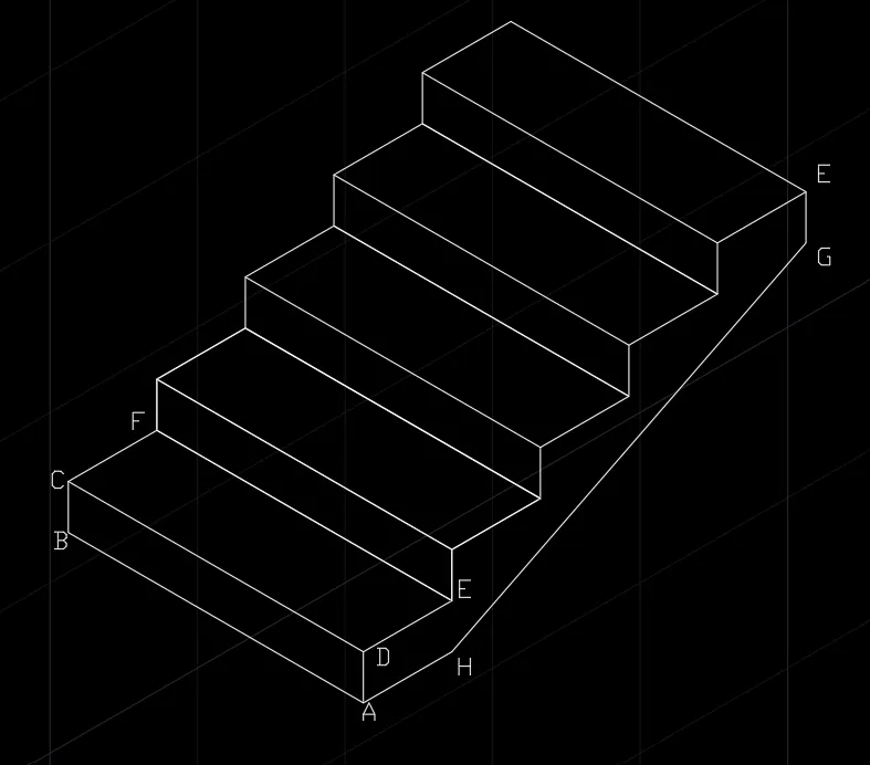
Draw Isometric view of STEPS
PROCEDURE: -
In Isometric snap select Isoplane Left
Choose polyline tool
Specify first point: A (1,1)
Specify next point: B (@1<150)
Specify first point: C (@0.15<90)
Specify next point: D (@1<330)
Specify first point: close to A
Using F5 change to Isoplane Top
Choose polyline tool and select point D
Specify next point: E (@0.3<30)
Specify next point: F (@1<150)
Specify next point: Join to point C and select exit.
1st step is drawn.
Select and copy both boxes ABCD and CDEF
Select base point as A and place the selected boxes at point E
2nd step is drawn
Place the selected boxes one step over the next step to form 3rd, 4th and 5th steps.
Using F5 key change to Isoplane Right
Choose Line tool and select point E at 5th step.
From 5th step at point E draw line by creating point G (@.15<270)
From 1st step at point A draw line by creating point H (@0.3<30)
Join these two points G & H for slab thickness.
Isometric view of steps is ready.
RESULT: -
6Q]
AIM: -
Create Gabble Wall in Isometric view
PROCEDURE: -
Select Draft settings
In draft settings select Isometric snap
Press F5 for ISOPLANE RIGHT
Choose line tool
Line Specify first point: A (0,0)
Specify next point: B (@1<30)
Specify next point: C (@2.42<90)
Specify next point: D (@1<30)
Specify next point: E (@-2.42<90)
Specify next point: F (@1<30)
Specify next point: G (@3<90)
Specify next point: H (@-3<30)
Specify next point: CLOSE
Choose line tool and select point G
Specify next point: I (@-1.5<30)
Specify next point: J (@1<90)
Close to A
Join points G-J and J-H
Erase lines GH, IJ &GI
Using F5 key select ISOPLANE LEFT view
Select point J and draw line of 0.3 units for wall thickness
Copy the 0.3 units line and place at points I, G, A &E
Copy the lines GJ, IJ, IA and ED and at a distance of 0.3 units previously drawn line for wall thickness.
Reduce the line length at point E to the line CD.
RESULT: -