Drafting of various geometries using Chamfer, Fillet tool in AutoCad
1Q]
AIM: -
Draw the figures using AutoCAD tools.
PRODEDURE: -
Select the command: DDPTYPE
Select point style
Select Multiple points command
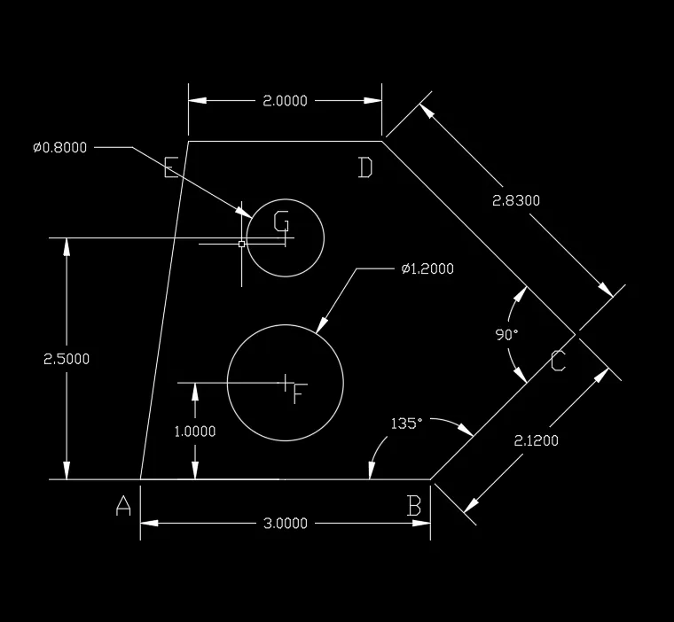
Specify a point: A (1,1)
Specify a point: B (@3,0)
Specify a point: C (@2.12<45)
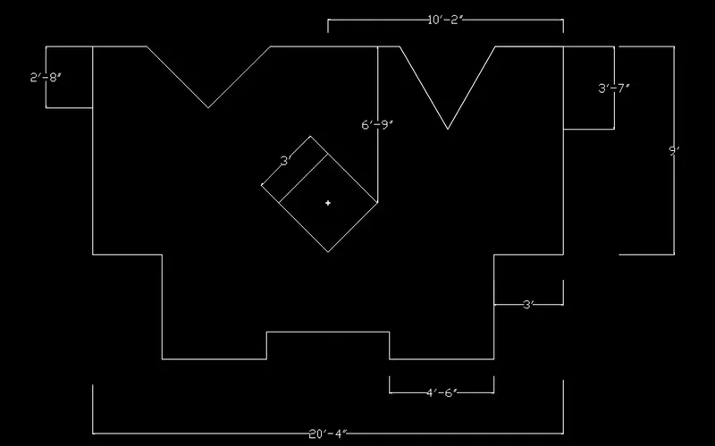
Specify a point: D (@2.83<135)
Specify a point: E (@-2,0)
Select line tool and join the points.
A- B - C- D- E- A
Select Multiple Points tool
Specify a point: A (1,1)
Specify a point: F (@1.5,1)
Specify a point: G (@1,0)
Select CIRCLE command
Draw a circle using F as centre and diameter is 1.2 units.
Draw another circle using G as centre and diameter is 0.8 units.
Now we got the required figure
Now, erase all the points.
RESULT: -
2Q]
AIM: -
Draw the figures using AutoCAD tools.
PROCEURE: -
Open Units command
Change length type to Architectural
Select LINE tool
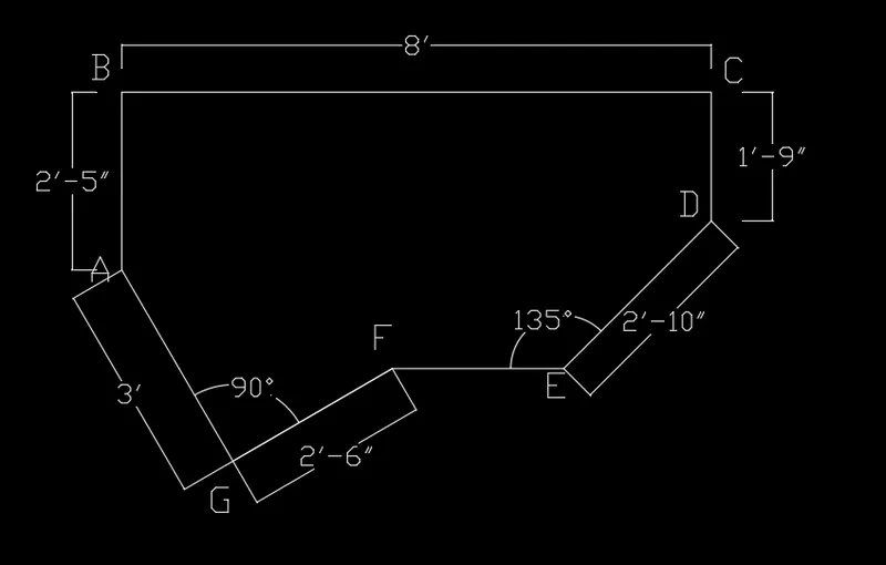
Specify 1st point: A (0,0)
Specify next point: B (@2’5” <90)
Specify next point: C (@8’ <0)
Specify next point: D (@-1’9” <90)
Specify next point: E (@-2’10” <135)
And from point E extend the line horizontally at 0 degrees to certain extent.
Select Line tool
Select 1st point as point A
Specify next point: G (@ -3’ <90)
Specify next point: F (@2’6” < 0)
Select ROTATE command.
Select objects: AG & GF lines
Select base point as Point A
Rotate the lines AG & GF such that GF has to touch the horizontal line from point E
After adjusting the lines use TRIM command to trim the extra lines
RESULT: -
3Q]
AIM: -
Draw the figures using AutoCAD tools.
PROCEURE: -
Select UNITS commands and change length type to Architectural
Set units to Architectural.
Select Multiple points tool
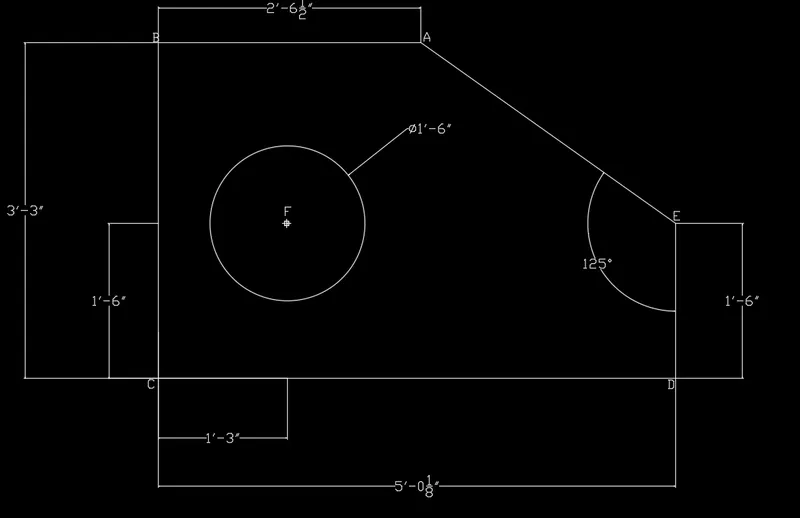
Specify a point: A (1,1)
Specify a point: B (@-2’6.5”,0)
Specify a point: C (@0, -3’3”)
Specify a point: D (@5’0.1”,0)
Specify a point: E (@0,1’6”)
Select LINE tool and join the points.
A- B - C- D- E- A
Select Multiple Points tool
Specify a point: click on point C
Specify a point: F (@1’3”,1’6”)
Select CIRCLE tool
With centre as F and diameter as 1’6” draw a circle.
RESULT: -
4Q]
AIM: -
Draw the figures using AutoCAD tools.
PROCEURE: -
Select UNITS commands and change length type to DECIMAL
Set units to Decimal.
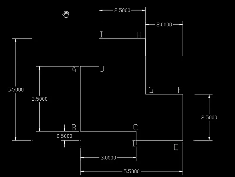
Select Multiple points tool
Specify a point: A (1,1)
Specify a point: B (@0, -3)
Specify a point: C (@3,0)
Specify a point: D (@0,0.5)
Specify a point: E (@2.5,0)
Specify a point: F (@0,2.5)
Specify a point: G (@2,0)
Specify a point: H (@0,3)
Specify a point: I (@-2.5,0)
Specify a point: J (@0,-2)
Select LINE tool and join the points.
A- B - C- D- E- F- G- H- I- J- A
RESULT: -
5Q]
AIM: -
Draw the figures using AutoCAD tools.
PROCEURE: -
Turn on the ORTHO command
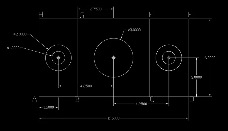
Select Multiple points tool
Specify a point: A (1,1)
Specify a point: B (@3,0)
Specify a point: C (@5.5,0)
Specify a point: D (@3,0)
Specify a point: E (@0,6)
Specify a point: F (@-3,0)
Specify a point: G (@-5.5,0)
Specify a point: H (@-3,0)
Select LINE tool and join the points.
A- B - C- D- E- F- G- H-A
Select Multiple points tool
Specify a point: click on point A
Specify a point: I (@1.5,3)
Specify a point: J (@4.5,0)
Select CIRCLE tool
Draw a circle using centre as point I with diameter 1.00 units
Draw a circle using centre as point I with diameter 2.00 units
Draw a circle using centre as point J with diameter 3.00 units
Select MIRROR tool
Select objects: circles with centre as I and diameter 1 and 2 units.
1st point of mirror: Centre of circle J and
2nd point of mirror: project vertically at 90 degrees from centre J to line GF
Don’t erase the source objects.
RESULT: -
6Q]
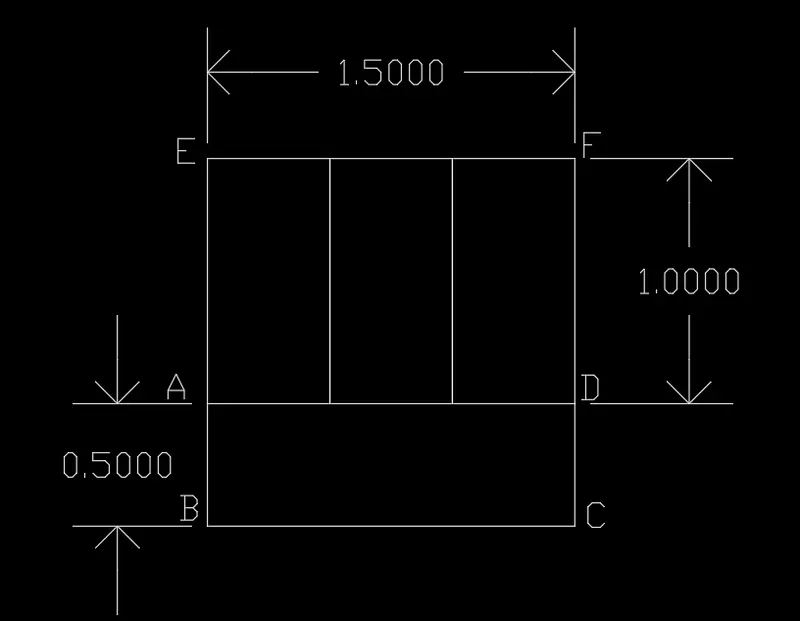
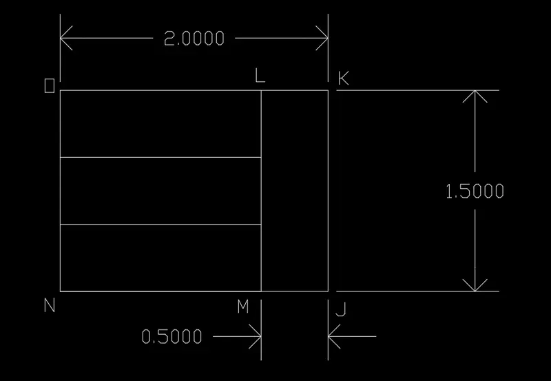
- FRONT VIEW
AIM: - Draw the front view of the given figure.
PROCEDURE: -
Select RECTANGLE command
Draw a rectangle ABCD with dimensions of length 1.5 and width 0.5 units
Select LINE command.
Specify 1st point: click on A
Specify 2nd point: E (@1<90)
Specify 3rd point: F (@1.5<0)
Specify 4Th point: - close to D
Select OFFSET command
Specify offset distance as 0.5 units select multiple option.
Give direction to offset line.
Divide the Rectangle AEFD into 3 small rectangles of size 0.5 * 1.0 units.
RESULT: -
- SIDE VIEW
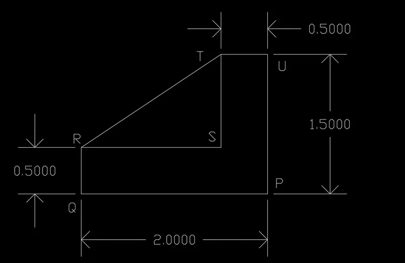
AIM: - Draw the SIDE view of the given figure.
PROCEDURE: -
Select LINE command.
Specify 1st point: P (1,1)
Specify 2nd point: Q (@-2<0)
Specify 3rd point: R (@0.5<90)
Specify 4Th point: S (@1.5<0)
Specify 5TH point: T (@1<90)
Specify 6th point: U (@0.5<0)
Specify 7th point: close to P
Select LINE tool
Join points T and R
RESULT: -
- TOP VIEW
AIM: - Draw the TOP view of the given figure.
PROCEDURE: -
Select RECTANGLE command
Draw a rectangle JKLM with dimensions of length 0.5 and width 1.5 units
Select LINE command.
Specify 1st point: click on point M
Specify 2nd point: N (@-1.5<0)
Specify 3rd point: O (@1.5<90)
Specify 4th point: close to L
Select OFFSET command
Specify offset distance as 0.5 units select multiple option.
Give direction to offset line.
Divide the Rectangle MNOL into 3 small rectangles of size 1.5 * 0.5 units.
RESULT: -
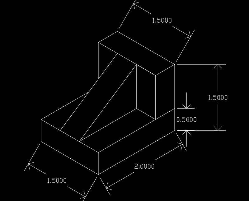
ISOMETRIC VIEW OF GIVEN FIGURE:
7Q]
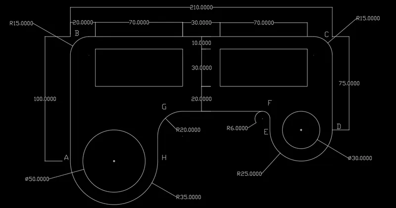
AIM: - Draw the given figure using AutoCAD tools
PROCEDURE: -
Select LINE tool
Specify 1st point: A (1,1)
Specify 2nd point: B (@100<90)
Specify 3rd point: C (@210<0)
Specify a point: D (@-75<90)
Specify a point: E (@-50<0)
Specify a point: F (@15<90)
Specify a point: G (@-90<0)
Specify a point: H (@-40<90)
Specify a point: close to A
Select Multiple Points command
Specify a point: click on B
Specify a point: @20, -10
Select RECTANGLE command
Select 1st point as new point
Draw a rectangle with dimensions of length 70 units and width 30 units.
Open OBJECT SNAP command and Turn on the END POINT snap and MID POINT snap
Select midpoint of line BC and draw perpendicular to line GF.
Select MIRROR command
Select object as Rectangle
Select 1st mirror point as midpoint of line BC
Select 2nd point as perpendicular line touches Line GF
Don’t Erase source object.
Select CIRCLE command
Draw circle using Centre as midpoint of line AH and radius 35 units
Select TRIM command
Select the object as circle to trim and line AH then press ENTER
Click on the circle inside the line AH.
Semicircle is formed with AH as diameter
Select Circle command
Select midpoint of line AH as centre and draw a circle with diameter of 50 units.
Select CIRCLE command
Draw circle using Centre as midpoint of line ED and radius 25 units
Select TRIM command
Select the object as circle to trim and line ED then press ENTER
Click on the circle inside the line ED.
Semicircle is formed with LINE ED as diameter
Select Circle command
Select midpoint of line ED as centre and draw a circle with diameter of 30 units.
Select FILLET command
Select 1st object as line AB
Enter radius value as 15 units
Select 2nd object as line BC
Select FILLET command
Select 1st object as line BC
Enter radius value as 15 units
Select 2nd object as line CD
Select FILLET command
Select 1st object as line EF
Enter radius value as 6 units
Select 2nd object as line GF
Select FILLET command
Select 1st object as line GF
Enter radius value as 20 units
Select 2nd object as line GH
RESULT: -
8Q]
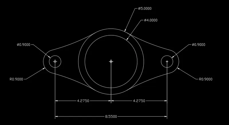
AIM: -
Draw the figures using AutoCAD tools.
PROCEURE: -
Turn on ORTHO command.
Select CIRCLE command
Draw concentric circles using centre point and diameter of 4 units and 5 units.
Select Multiple Points command
Specify a point: click on the centre point of circle with diameter 5 units.
Specify a point: @4.275,0
Using this new point draw concentric circles using centre point and diameter of 0.9 units and radius 0.9 units.
Turn on the CENTRE snap in OBJECT SNAP command
Draw vertical lines passing through centre of circles.
Select TRIM command and Select circle of radius 0.9 units and vertical line passing though this centre.
Trim the inner circle part inside this line.
Select OFFSET command and multiple option
Select 1st object as this half circle and move the cursor to the circle with diameter of 5 units.
An offset line at top is formed connecting these two circles and then repeat the process to form another offset at bottom.
Select MIRROR command Select the objects as these offset lines and circles with diameter 0.9 units and half circle.
Select mirror line as vertical line passing through circle centre of diameter 5 units.
After forming the mirror image don’t erase the source objects.
RESULT: -
9Q]
AIM: -
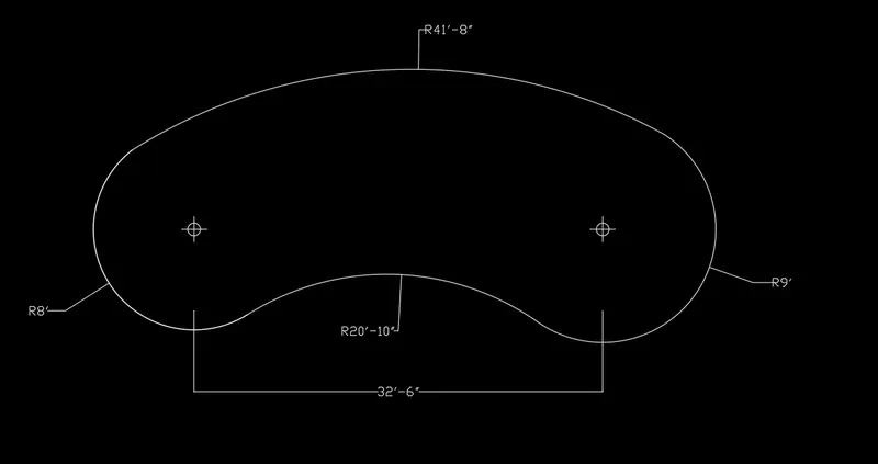
Draw the given figure using AutoCAD tools
PROCEDURE: -
Select CIRCLE command and select centre and radius option
Draw circle with radius = 8’
Select ORTHO command on
Select Multiple points command
Select 1st point as circle centre and specify next point: @32’6” <0
Select CIRCLE command
Draw a circle using centre and Radius method: centre as new point and radius is 9’ units.
Select FILLET command and at bottom of the circles,
Select 1st object as circle with radius 8 units
And enter radius of fillet as 20’10” units.
Select 2nd object as circle with radius 9 units.
Select ARC command and select start end radius option.
Select start point as point on circle with radius 9 units
And end point as point on circle with radius 8 units
Enter the radius as 41’8” units.
Give direction to the ARC
Adjust the ARC and trim the unnecessary objects
Circles in between two arcs should be trimmed according to given figure.
RESULT: -
10Q]
AIM: -
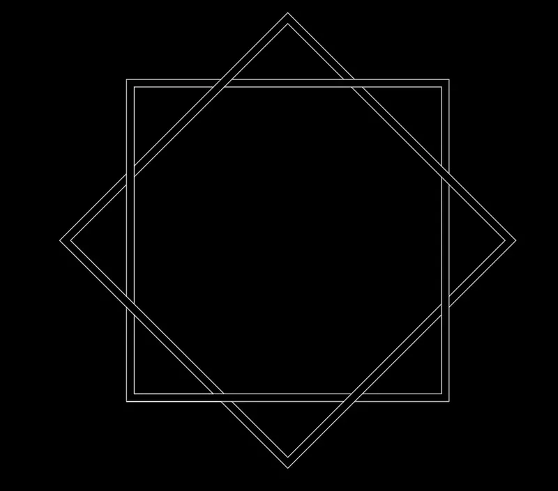
Draw the given figure in AutoCAD
PROCEDURE: -
Select Rectangle command and select dimensions of size 10 * 10 units
Select offset command
Specify offset distance as 0.5 units
Select OBJECT SNAP command and Turn on the Geometric Centre snap
Select the ROTATE command and select the copy option
Select the objects as both squares to rotate.
Specify the base point as Geometric centre of square
Rotate the squares to 45 degrees
Select the TRIM command
According to given figure Trim the Sides of the square
RESULT: -
11Q]
AIM: - Draw the given figure in AutoCAD
PROCEDURE: -
Tun on ORTHO command
Select line tool
Specify 1st point: A (0,0)
Specify 2nd point: B (@-1’2” <90)
Specify 3rd point: C (@4’6” <0)
Specify 4th point: D (@4’6” < 90))
Specify 5th point: E (@3’< 0)
Specify 6th point: F (@9’<90)
Specify 7th point: G (@-10’2” <0)
Specify 8th point: H (@-12’4” <90)
Close to A
Select MIRROR command
Select the object as complete figure and
Select the GH line as mirror line
After the mirror image formed don’t Erase the source object
Select Multiple points command
Specify a point: click on point G
Specify a point: I (@0, -6’9”)
Draw a square of Size 3’ * 3’
Using ROTATE command, rotate this square to 45 degrees
Open the OBJECT SNAP and turn on the Geometric Centre
Click on the Geometric centre of square and place it at point I
Select Multiple point command
Specify a point: click on point G
Specify a point: J (@5’1”, -3’7”)
Draw a line perpendicular from the point J to line GF (Right)
Select CHAMFER command and select the Angle option
Specify the length of Chamfer as 3’7” and d angle as 30 degrees
Select the first line as perpendicular line and second line as GF(Right)
Select CHAMFER and repeat the process for the other side.
Select Multiple point command
Specify a point: click on point G
Specify a point: K (@-5’1”, -2’8”)
Select Line command and draw perpendicular line from point K to line GF (left)
Select CHAMFER command and select the Angle option
Specify the length of Chamfer as 2’8” and d angle as 45 degrees
Select the first line as perpendicular line and second line as GF (left)
Select CHAMFER and repeat the process for the other side.
RESULT: -