Project 2_Design & Analysis of a Hostel building at Guwahati, Assam
AIM
To model, analyze, design, and preparation of construction drawings.
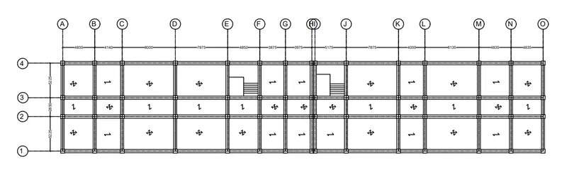
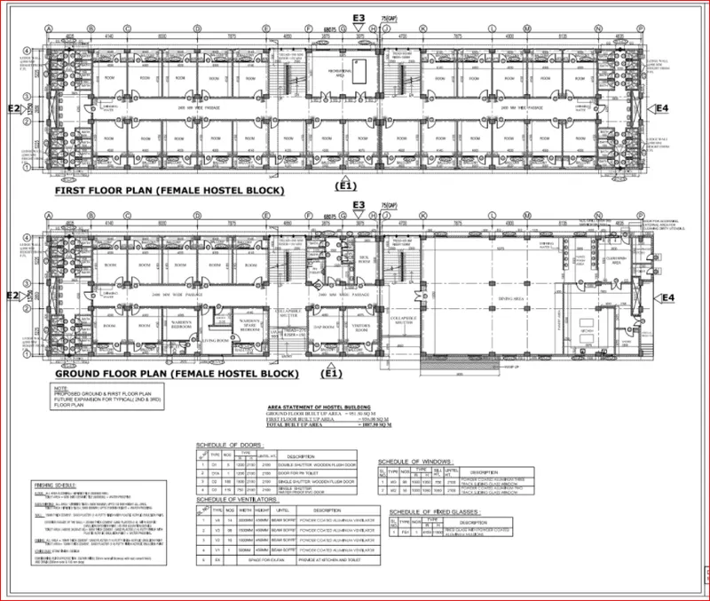
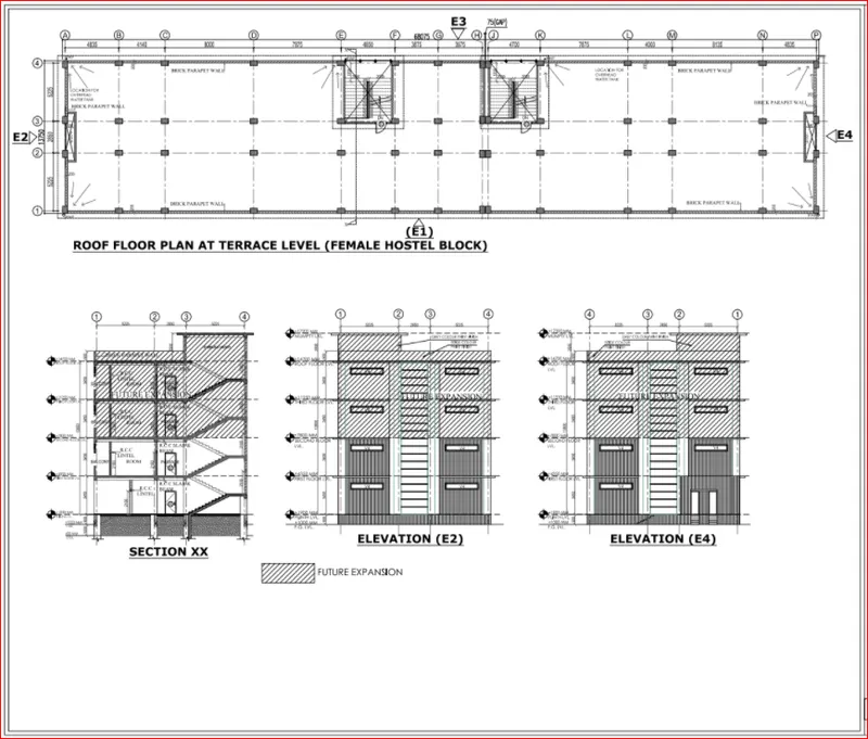
The architectural drawings of a G+3 RCC building is provided. The following information on the building is to be used:
Location – Guwahati, Assam
Function – Hostel block in an academic institute
INTRODUCTION
ETABS is an engineering software that is used for multi-story building analysis and design. Modeling tools and templates, code-based load prescriptions, analysis methods and solution techniques, all coordinate with the grid-like geometry unique to this class of structure.
Here we are modeling and analyze a G+3 building
And we model and analyze the footing using ‘Safe’
CSI SAFE (Slab Analysis by the Finite Element Method) is the best tool for designing concrete slabs and foundations by the Computer and Structures
Codes used
- IS 875 part 1
- IS 875 part 2
- IS 13920
- IS 1893
- IS 2911 part 2
- IS 456
- SP 34
PROCEDURE
Step 1:Open ETABS software
Open a new model
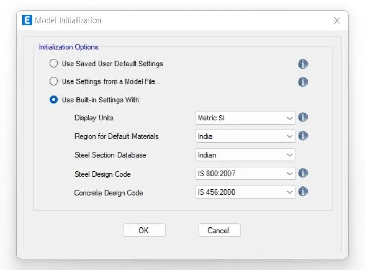
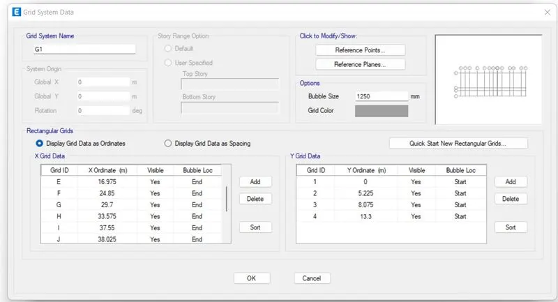
Step 2:Select Custom grid spacing
Select ‘edit grid data’
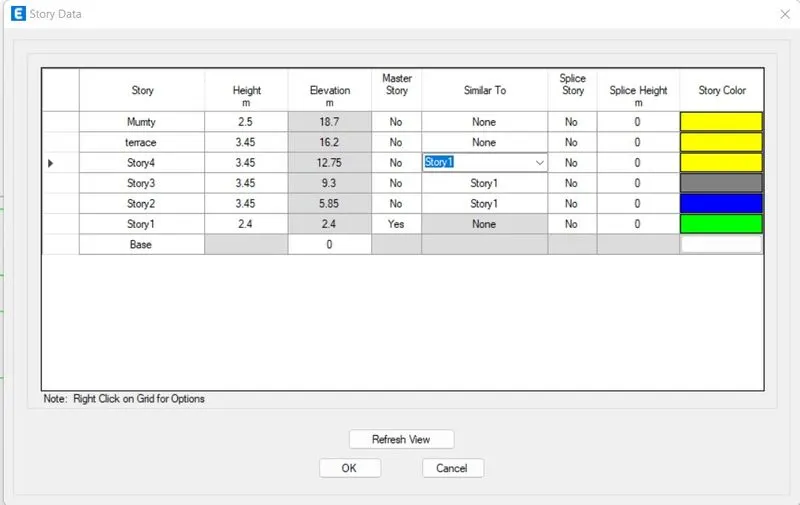
Step 3:Select story data
Select edit story data
Step 4:Select last story -right click -select add story-keep existing story height
Step 5:Select story 1 and make it master story
Make all other stories similar to story 1
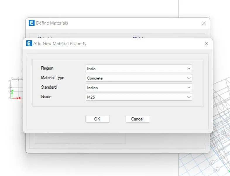
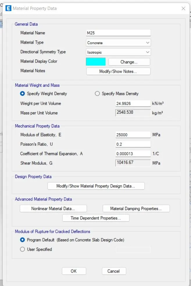
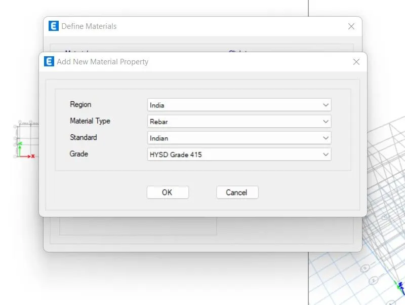
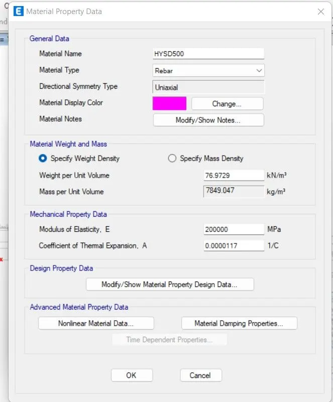
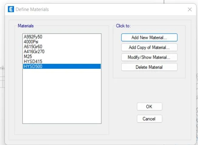
Step 6:From define tab select material property
Add M25 concrete and HYSD415 and HYSD500 rebar
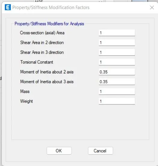
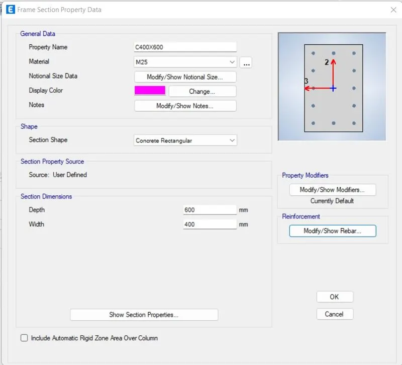
Step 7:From define tab select section properties
Then select Frame sections -Add new sections
Add columns and beam
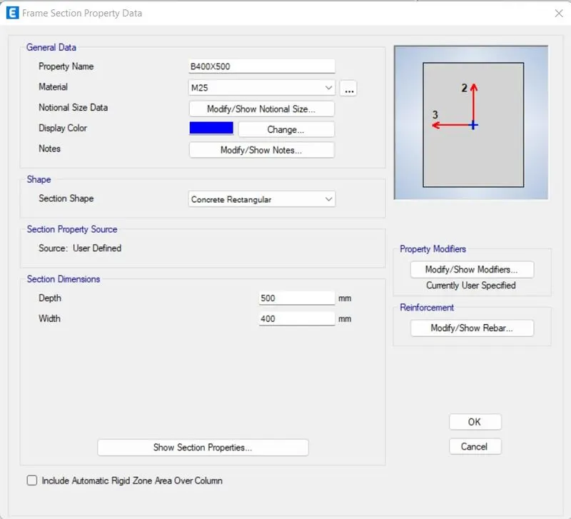
Step 8:From define tab select section properties
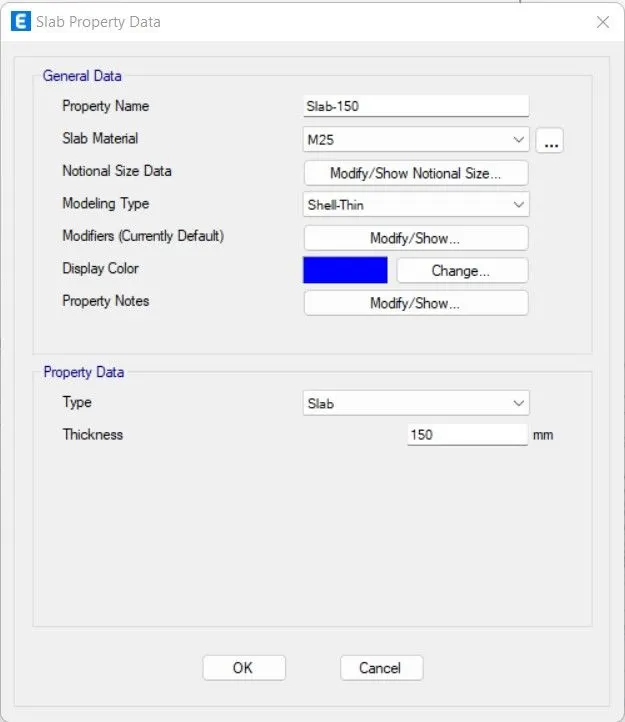
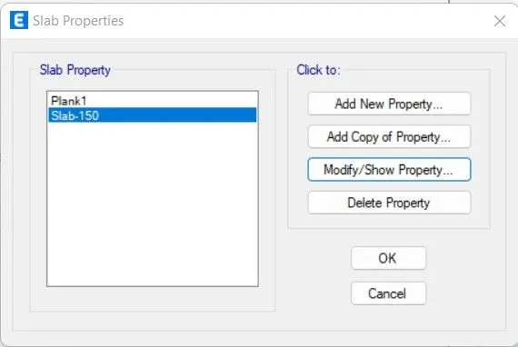
Select slab sections
Add new property
Add slab properties
Step 9:Select quick draw columns
Select all stories
Select the column size
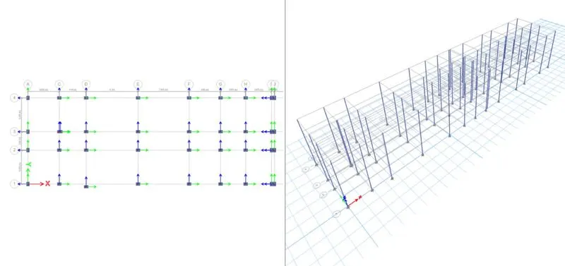
Step 10:Select quick draw beams
Select all stories
Select the beam size
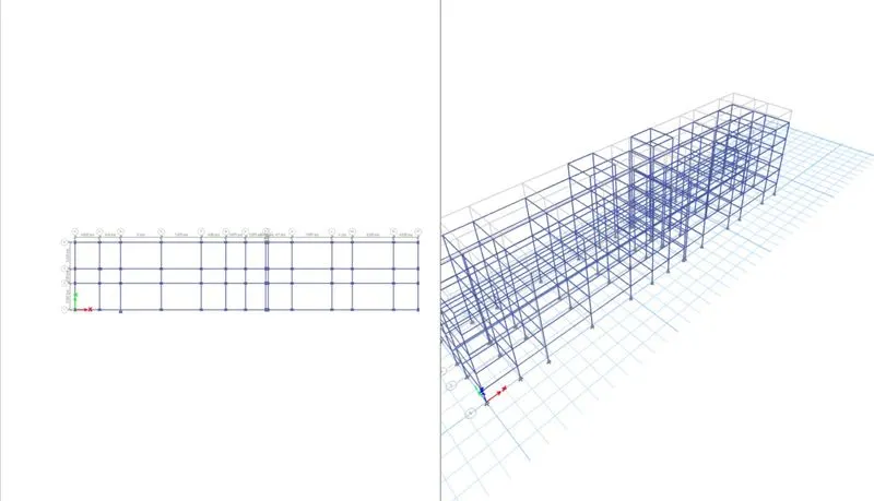
Step 11:Draw floors and cantilever slabs
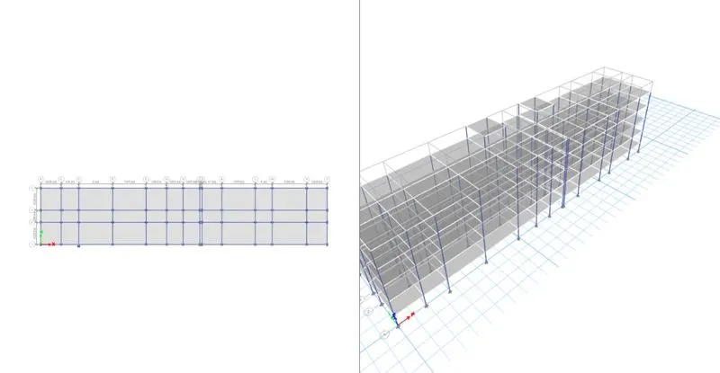
Step 12:Select define
Select load patterns
Add load patterns
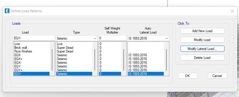
Step 13:Select the beam with brick wall and assign the load
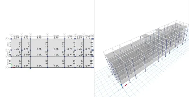
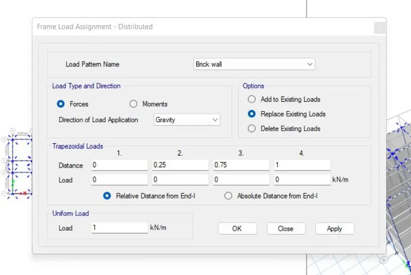
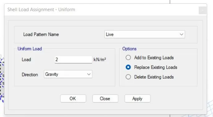
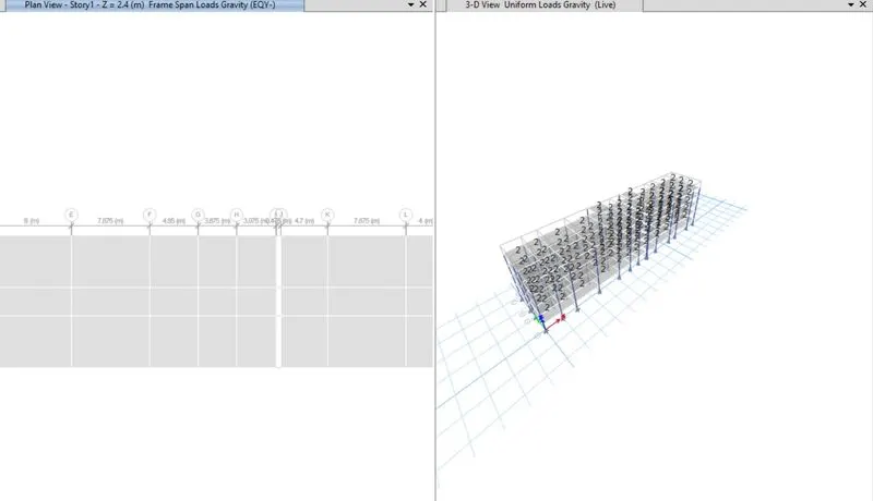
Step 14:Assign live load
Step 15:Select Design
Live load reduction factor
Step 16:Define-Select mass source
Click on modify/Show mass source
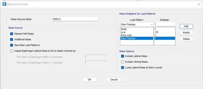
Step17:Define-function-Response spectrum
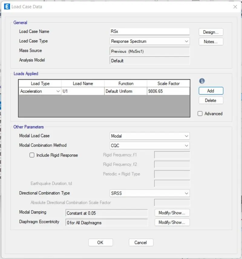
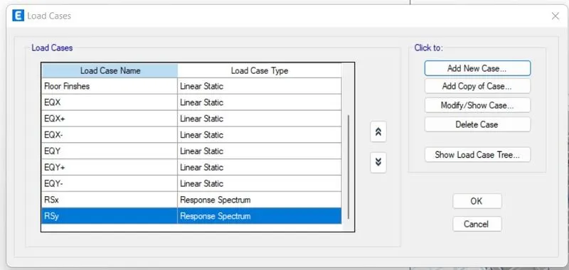
Step 18:Define-load cases-Add new load cases
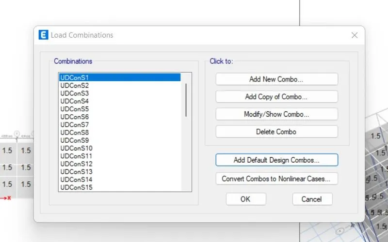
Step 19:Select ‘Run analysis’
Step 20:Display-Show tables
Structure output-model information
Select -modal participating mass ratios
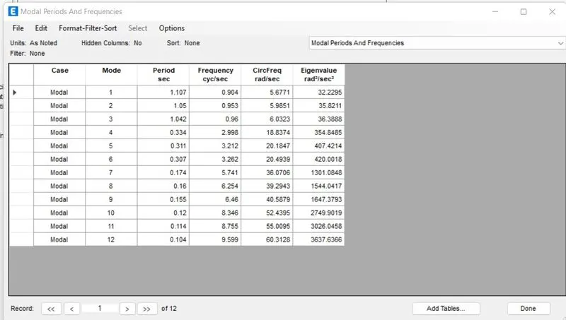
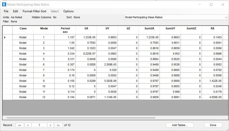
Select -Display-Story response
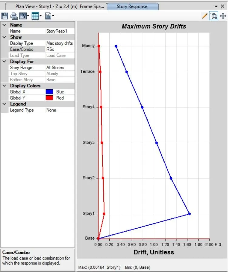
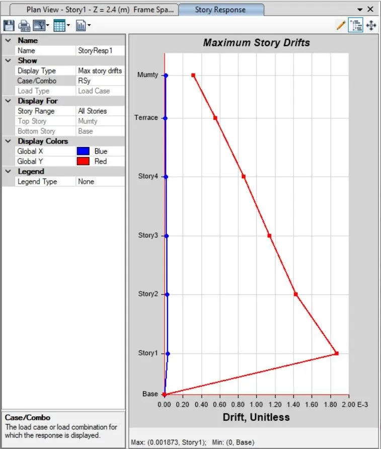
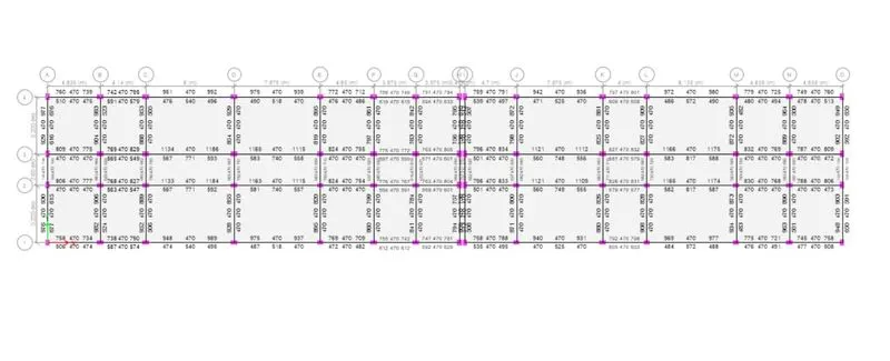
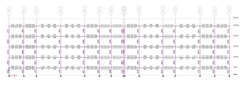
BEAM
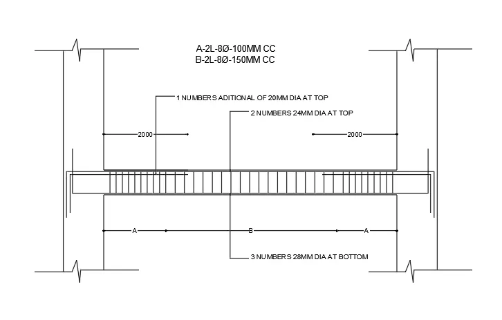
Longitudinal Reinforcement

Ast at top =1186 mm^2
Ast at bottom=771 mm^2
At top provide 2 number of 24 mm diameter bars and one 20 mm diameter bar
Ast=(2 x 452) + (1x314)
=1218 mm^2
At bottom provide 3 number of 20 mm diameter bars
Ast=(2 x 314)
=942 mm^2
Ln/4=8000/4=2000
Anchorage length=Ld+10db
Ld = φ σst/4τ bd
τ bd value from the IS 456:2000 ,we know=2.72
So, Ld for T-24 rebar,
Ld=((24x500)/(4x2.72))
Ld=1100 mm
Anchorage length(24mm bar)=1100+10*24
=1340mm
Anchorage length(20mm bar)=919+10*20
=1119mm
Shear Reinforcement

As per IS 13290,Shear reinforcement length from end support =2d
d=500-25-32
=443
2 d=886
Provide 2 leg 8 mm diameter bars
Maximum shear =1073
1073/100=10.73=10
Spacing
d/4=443/4=110
8db=8*24=192
100mm
So,
Provide 8 mm 2 legged bar at 100 mm c/c spacing at ends
Midspan
768/100=7.68=8
Provide 8 mm dia bars at 150 mm c/c spacing
COLUMN
Longitudinal Reinforcement

Ast max =4489 mm^2
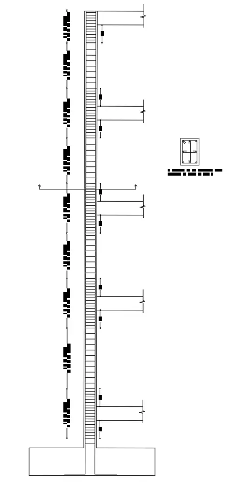
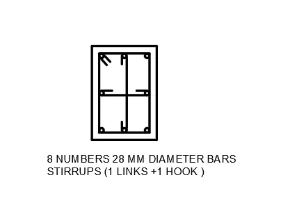
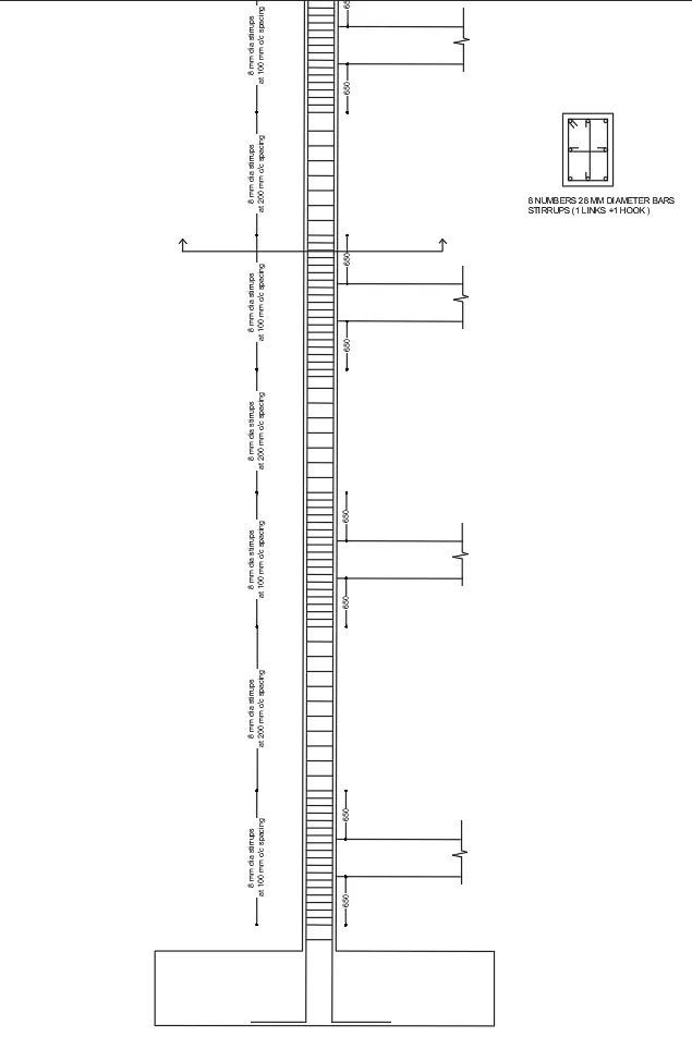
Provide 8 number of 28 mm diameter bars
Ast=(8x 616)
=4928 mm^2
Which is greater than the Ast required
Hence ok
Anchorage length=Ld+10db
Ld = φ σst/4τ bd
τ bd value from the IS 456:2000 ,we know=2.24
So, Ld for T-28 rebar,
Ld=((28x500)/(4x2.24))
Ld=1562 mm
Anchorage length=1562+10*28
=1842mm
Shear Reinforcement

Special confinement from IS13296-2016 Clause 8.1
1)Lo should not less than
a)Larger column dimension 650
b)⅙ of clear span of column
c)450 mm
Lo is taken as 650 mm
2)Confinement spacing should not more than
a)¼ of smaller column dimension -450mm
b)6 times diameter of column main bar -6*28=168mm
c)100 mm
Taken the lower value
The values are similar for all floors ,There is no shear requirement due to loading
The minimum shear reinforcement is required as per ductility standards
Provide 8 mm lateral ties at 200 mm c/c spacing
Provide 8 mm lateral ties at 100 mm c/c spacing in confinement zones
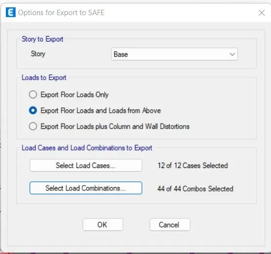
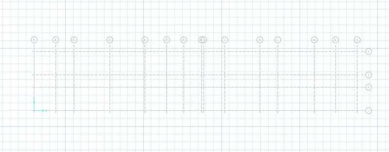
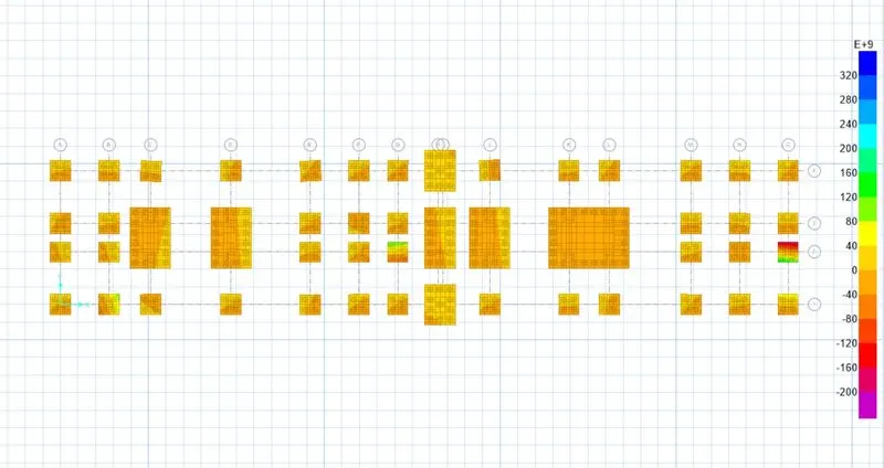
Step 21:Export the model from Etabs to Safe
Step 22:Add materials
M25 and FE500
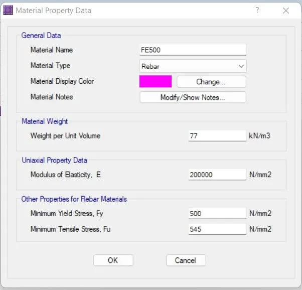
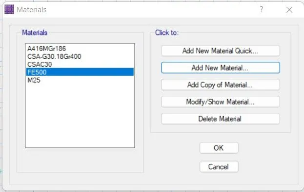
Step 23:Add slab properties
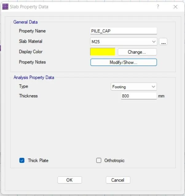
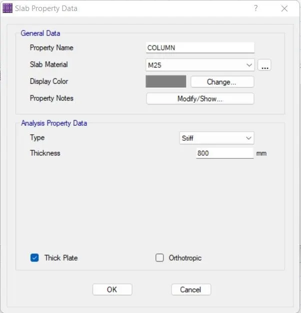
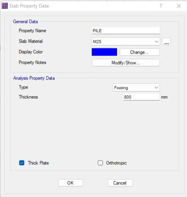
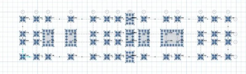
Step 24:Draw the pile cap
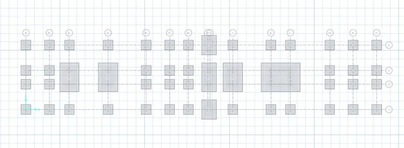
Step 25:Draw the points
Step 26:Draw the pile
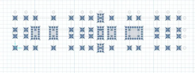
Step 27:Assign load combinations
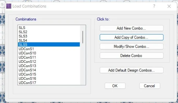
Step 28:Run analysis
RESULTS
Beam Reinforcement detials
Column Reinforcement detials
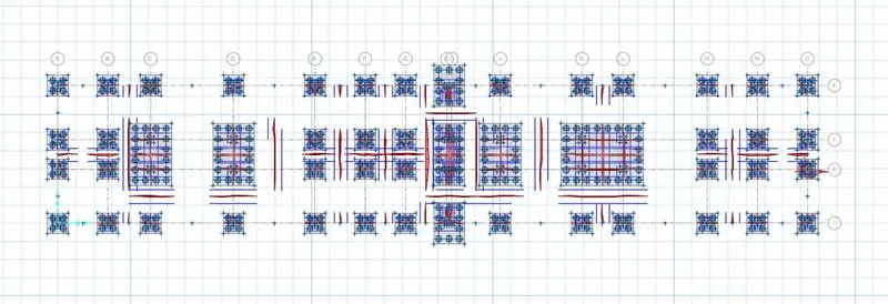
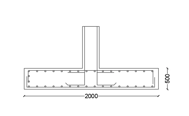
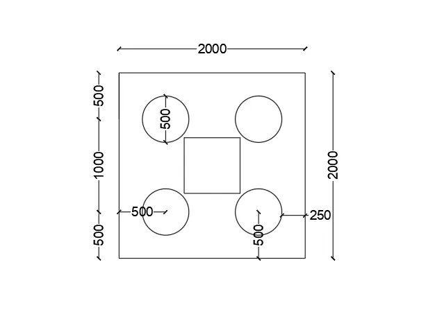
Footing Reinforcement detials
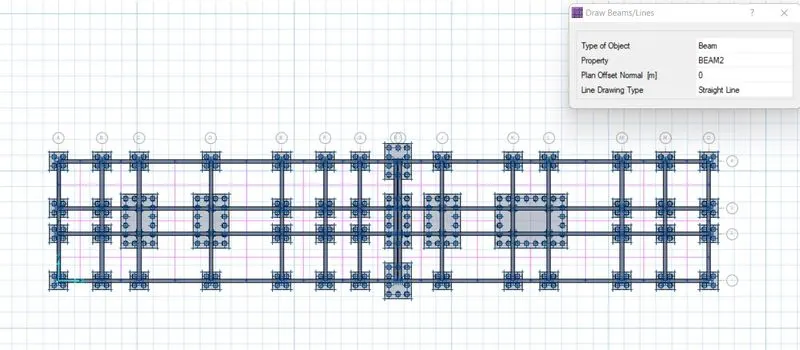
Floor Farming plan