Project 2_Creating a 3D rendered model for a Residential Building in AutoCad
CREATING A 3D-RENDERED MODEL FOR A RESIDENTIAL BUILDING IN AUTOCAD
Aim:
To create a 3-dimensional residential building model with a rendered view in AutoCAD.
Introduction:
Rendering is creating a raster image based on 3D objects in a scene. A renderer is used to calculate the appearance of the material attached to the thing in a scene, and how lighting and shadows are calculated based on the lights placed in a scene.
Environmental and exposure settings can be adjusted to control the final rendered image. The basic rendering workflow is to attach materials to the 3D objects of a model, place user-defined lights, add a background and start the renderer with the RENDER command.
Lights and materials can be added to a 3D model before a photorealistic image is rendered.
Rendering quality can be changed by using the cameras, sunlight different types of lights like point light, spotlight, distant light, etc. Using these commands properly can improve the rendering to a great extent.
Procedure:
- Open AutoCAD and go to 3D modeling.
- Initially set the units of the drawing as decimal (mm).
- Now, set the limits of the drawing:
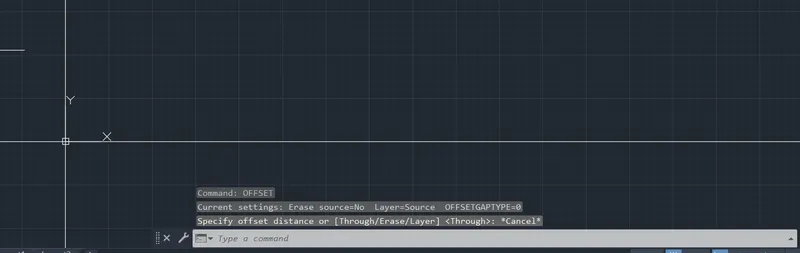
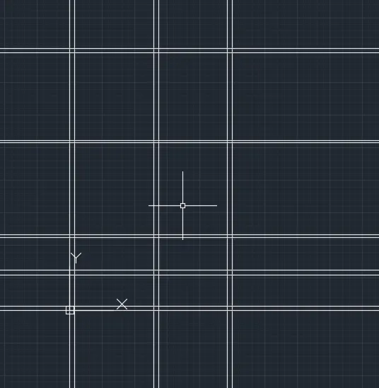
- Using the Xline command take reference from the plan.
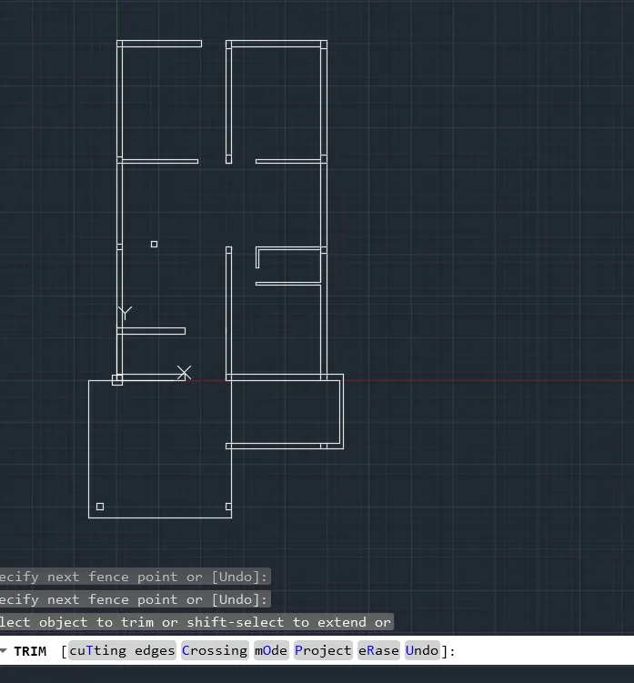
- By using the trim command, trim off the unwanted lines.
- Then provide openings for doors and windows.
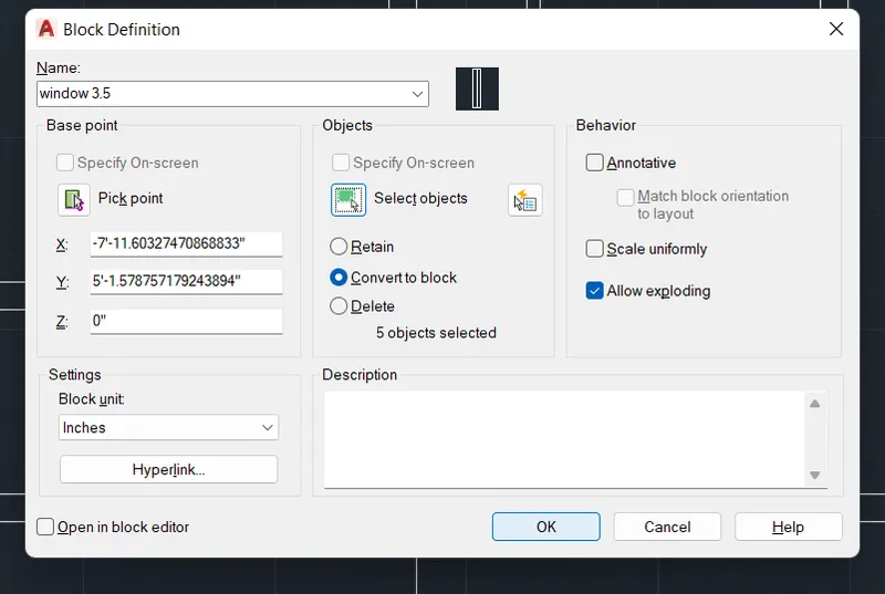
- Block command is used to create blocks of windows and doors that can be placed in plan.
- After completion of the plan, give proper dimensions to the plan using dim linear command.
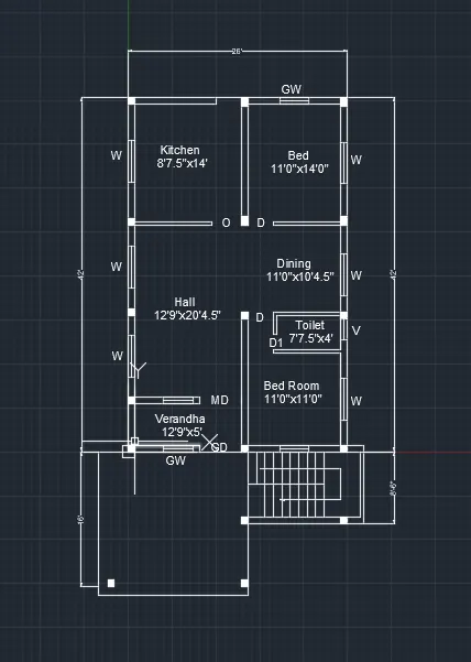
- Create ground floor and first-floor plans and then provide proper texts.
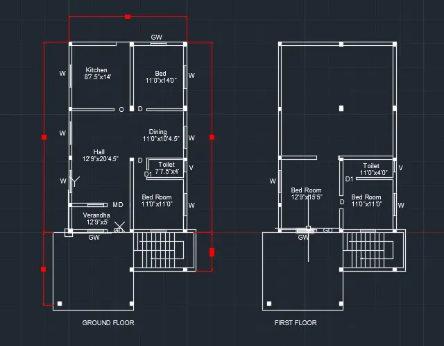
- After that, change the drawing space to 3d modelling to create 3d structure.
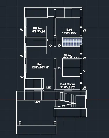
- Using the extrude command and presspull command create 3d wall and windows.
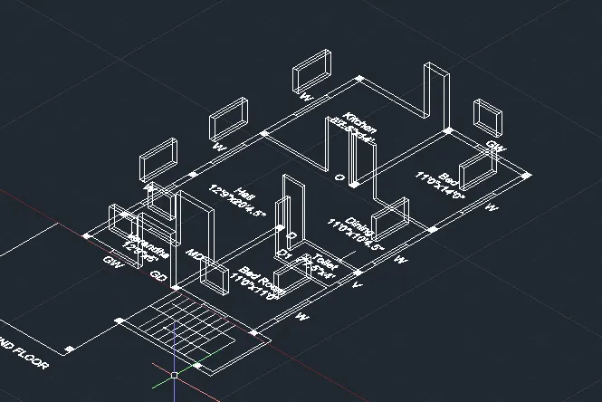
- Layer command is used to create different layers to differentiate different components and give proper colour.
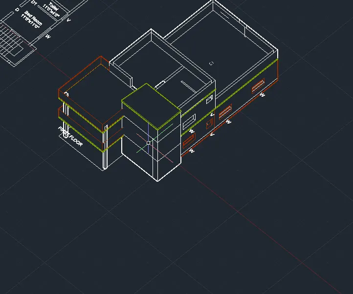
- 3D orbit command is used to view the plan of the building and view different of the building.
- UCS command is used to change the face and use the face for drawing.
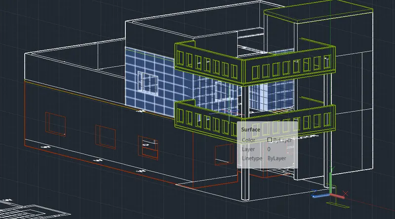
- After completion of all the components, using the render environment command the render components are changed and given as per the required view.
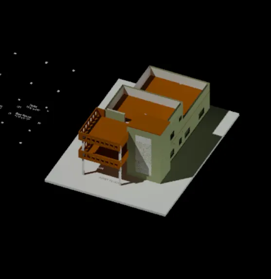
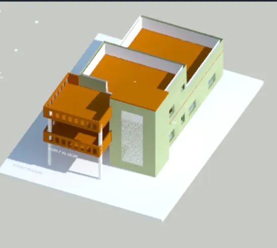
- By using the render command, the 3D image of the building can be created realistic.
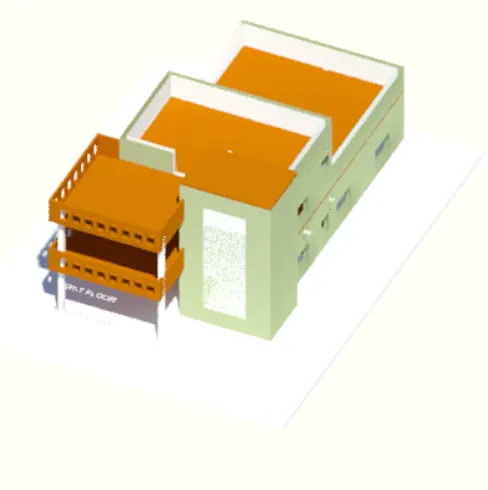

RESULT:
All the drawings are drawn using the proper commands and with the given specifications. Mainly 3Dface, ucs, hatch, sweep, rotate3d, and 3Dorbit are used in this drawing to technically specify the different components in the drawing. By using Render command the house plan is viewed architecturally.