Project 2_Creating a 3D rendered model for a Residential Building in AutoCad
Aim : To Create a 3 dimensional model of the residential building with a rendered view.
Introduction : The main aim of this project is to create the plan in 2d and convert it into 3D using AutoCAD 3Dimensional and Rendering tools.The 3d tools are as folllows.
- Revolve
- Extrude
- Sweep
- Union
- Subtract
- Render
- Rotate3d
- Boundary
- Solidedit
Commands Used:
- Offset
- Xline
- Layer
- Text
- Dimlinear
- Fillet
- Circle
- Line
- Rec
- Trim
- Solidedit
- Revolve
- Extrude
- Sweep
- Union
- Subtract
- Render
- Rotate3d
- Boundary
- Solidedit
Procedure:
Step 1:
- Create a new AutoCAD file with imperial settings.
- Command D - units type as "Decimal" and set the precision also
- Set the limits with command "LIMITS" and enter zoom all.
- Command - UNITS to change the unit option as "Decimal" and set the precision.
- Command - Xline
- Specify the 1st point and draw the horizontal and vertical lines to form a rectangle
- Command - Offset
- Select the through option and object and specify the offset distance for the Wall thickness.
- Selct the object and repaet the same process to form a layout of ground floor plan.
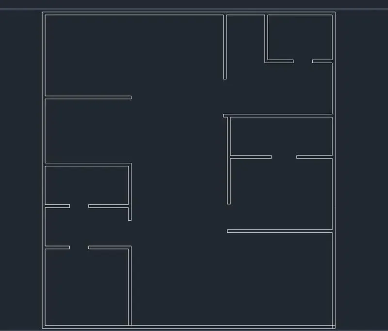
Step 2:
- Command - line
- Specify the 1st point and draw a line along y axis for the window1 and window2 wherever required.
- Create the door openings using the trim option.
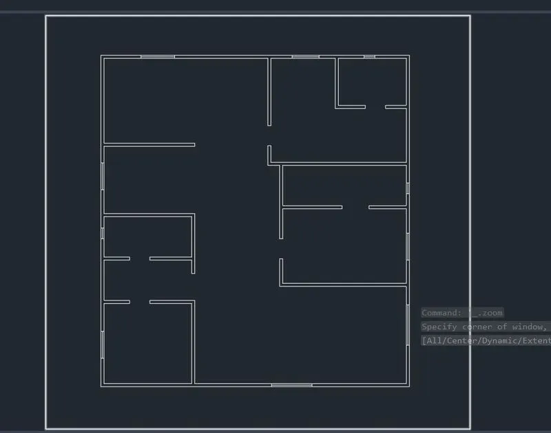
Step 3:
- Command - Text
- Specify the 1st point and enter the text required for the plan, use layer option to mention the layers
- Command - Dimlinear
- Specify the starting and end point and mark the dimensions for the plan.

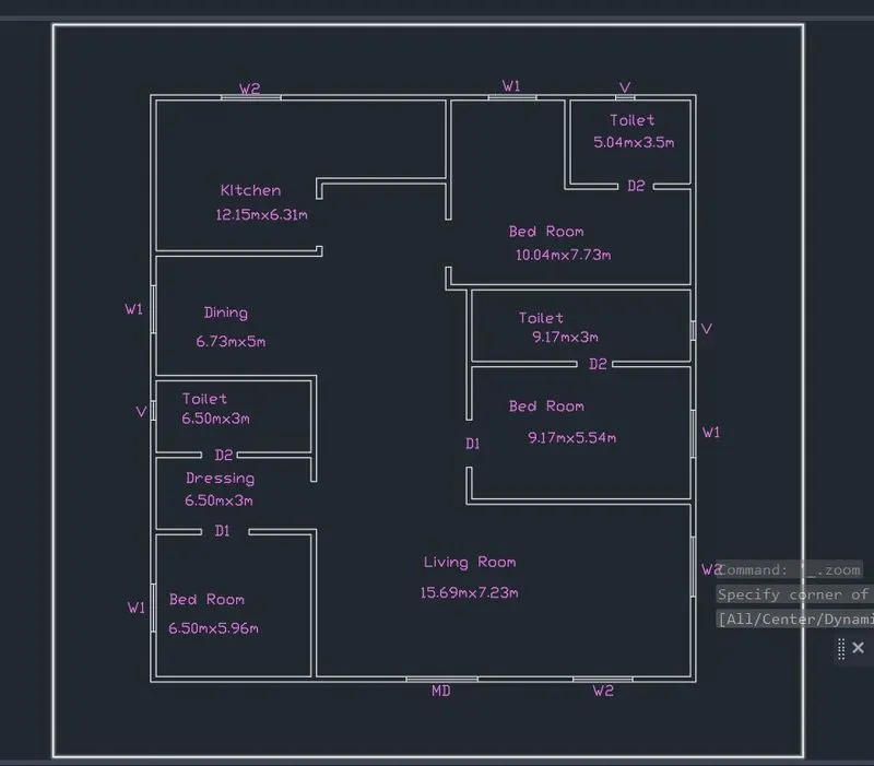
Step 4:
- Command - Boundary
- Select the region option and pick the objects and press enter and mark the regions wherever required, Command - shade to view the regions created.
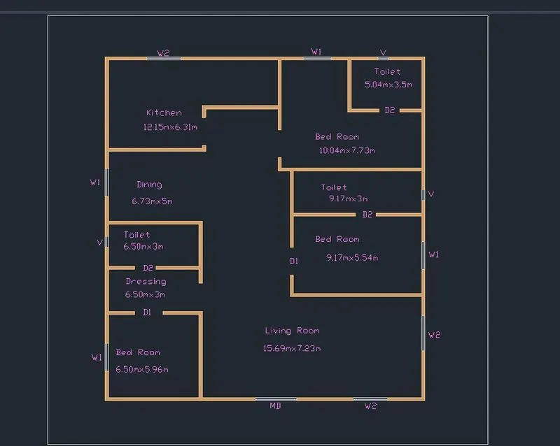
Step 5:
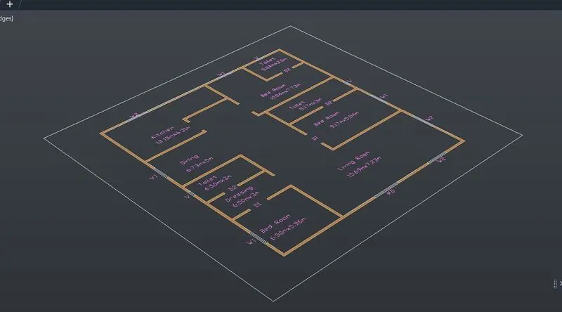
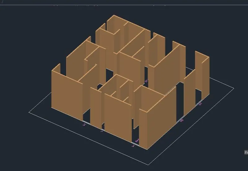
- To project walls to convert the plan from 2d to AutoCAD 3D.
- Now in settings select 3D Modelling and visual style control to 2D wireframe to move to AutoCAD 3D.
- Select the south west isometric view.
- Turn off all layers except the wall layer.
- Command - Extrude ,press enter, move mouse in upward direction and specify height and press enter. Now the 3D wall is created.
Step 6:
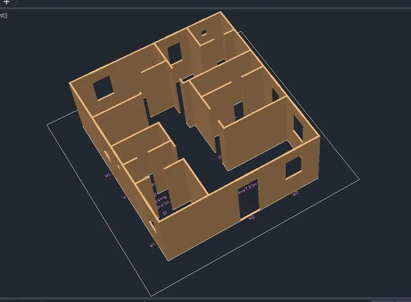
- Command - REC, draw a rectangle connecting the top of all door openings.
- Command - Extrude and press enter, move mouse in downward direction and specify height and press enter. the door cut-outs is created
- Command - REC, rectangle was drawn across all the window portion at the plinth level.
- All the windows, doors and ventilator has been created.
Step 7:
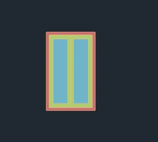
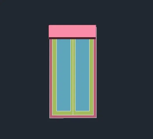
- Designing of 3d doors
- Go to Top view and create a rectangle for window size
- Clicking on the home button to get the 3d view
- And draw the slab for the window using the line command
- Use region and subtract option and shade to get the region
Step 8:
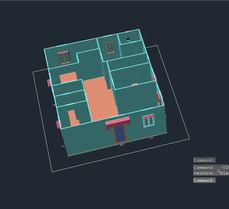
- The materials is copied wherever it is required, using th 3D rotate command it was rotated in the direction and placed at their respective positions
- Apply lights outside the plan using the line command.
- In visualization tab select the create light option ,turn off the default lighting and then place the lights at the centre of diagonal, click on intensity factor click on 20 and click enter
Step 8 :
- Turn off the wall layer and draw the rec in the top view and extrude it to height of 1m to form the floor level
- Turning on the wall layer draw a rectangle on the top portion
- Command - Extrude and enter and extrude the roof level using the layer option to differentiate it.
- Command copy, select the whole plan and copy it place it on the top portion of the ground floor
- Command solidedit, select the face option and select the top portion of the extruded part and copy and place it to left portion
- Using the subtract option, subtract the inner and outer wall
- Extrude the wall to an specific height and to form a top portion
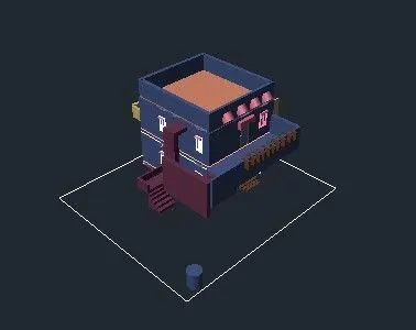
- Draw the stairs using the presspull option and extrude it and rotate it as required
- Change the layers to form perfect plan.
Step 9:
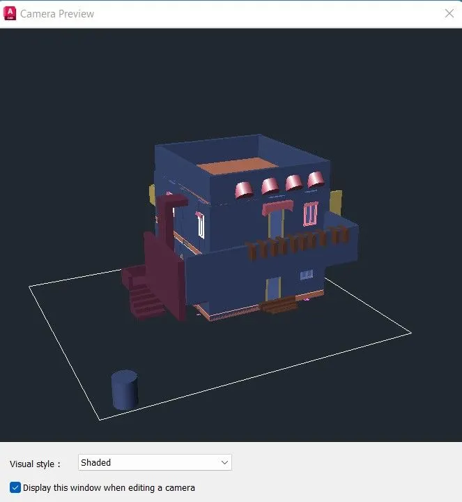
- Command - Camera, place the camera and create a face mention the height of the view and the lens
- To focus the view as required, place it as required to view the plan
- Click on the camera option so that the projected view has been shown.
Step 10:
- From the visualization tab, select the render option and select the environment and exposure option
- Select the environment on and image based lightings as "Grid Lights"
- Select the Render to size option and the image will be downloaded and save it
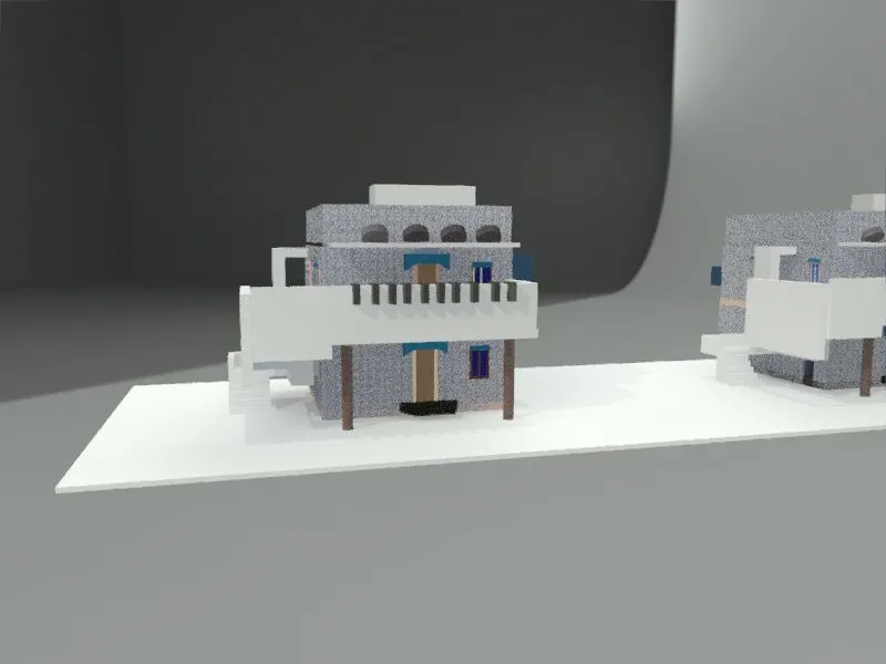
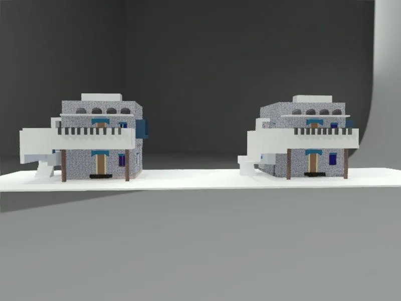
- Rendering has been done and the resultant images from different camera position is as shown.
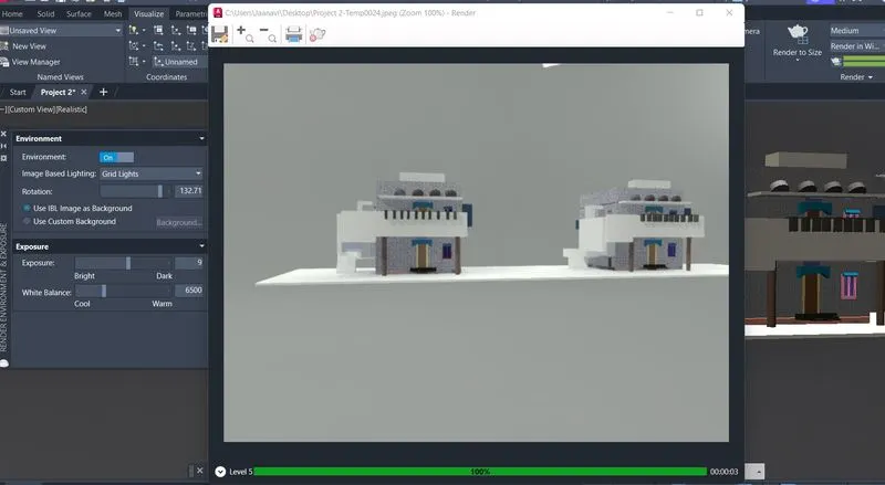
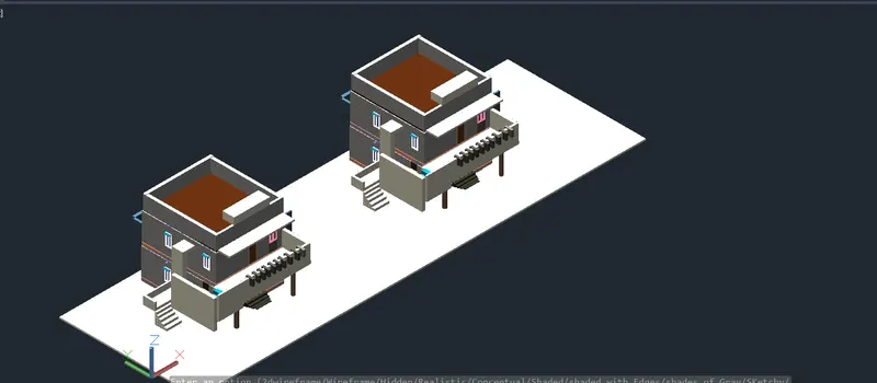
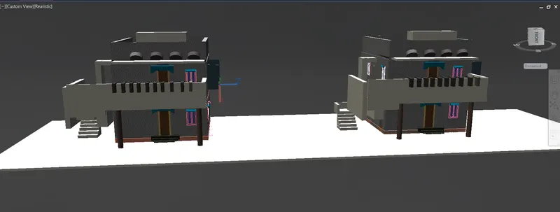
The final view of the plan is below:
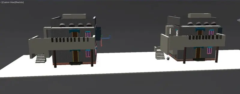
Result : A 3 dimensional model of the residential building with a rendered view has been created and shown below