Project 2_Creating a 3D rendered model for a Residential Building in AutoCad
CREATING A 3D RENDERED MODEL FOR A RESIDENTIAL BUILDING IN AUTOCAD
Aim:To create a 3 dimensional model of the residential building with a rendered view in AutoCAD.
Introduction:
Rendering is a process of creating a raster image based on 3D objects in a scene. A renderer is used to calculate the appearance of the material attached to the object in a scene.Environmental and exposure settings can be adjusted to control the final rendered image. The basic rendering workflow is to attach materials to the 3D objects of a model, place user defined lights, add a background and start the renderer with the RENDER command.
Procedure:
- Open the AutoCAD and go to 3D modelling.
- Initially set the units of the drawing as decimal (mm).
- Now, set the limits of the drawing:
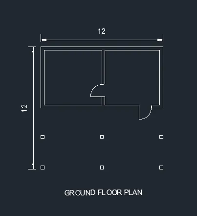
- Now create a 2D plan for a residential building with the help of commands like line, offset, trim etc.
- Also region all the walls and other areas to be extruded , because only closed area can be extruded or presspull
- Now, create the elevation of the same by using lines, offset, trim and other necessary tools in AutoCAD.
-
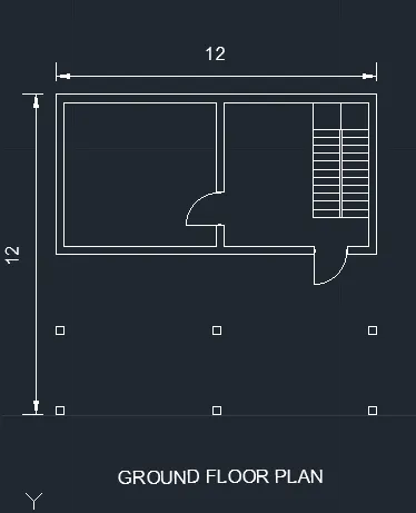
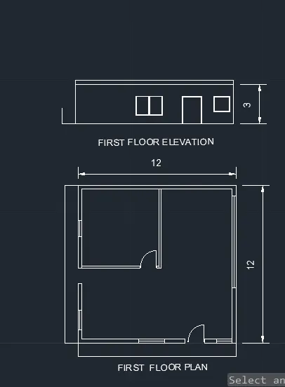
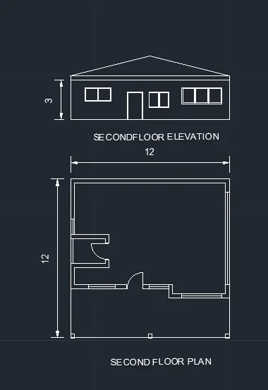
- Now, we have to create the 3D model of the same.
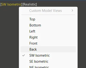
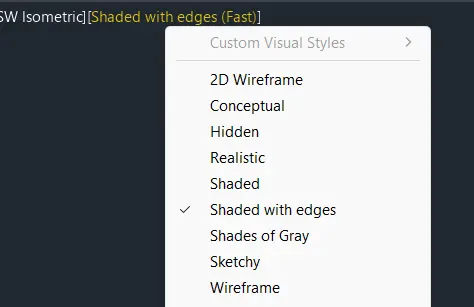
- For this move to 3D modelling workspace in the settings. Choose the SW Isometric view, and select the SHADES OF GREY instead of 2d wireframe from the status bar
- Now, copy the plan separately.
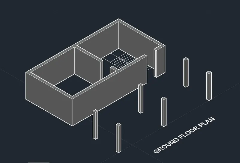
- Now use the extrude or presspull command to draw walls. Drag the cursor in the direction of wall height
- Then create different necessary layers like 3D walls, 3D windows etc.
- Now, copy the first-floor plan and create the boundary region.
- Then extrude the 3D wall leaving the space for the windows.
- Now, create the floor for ground floor by drawing a rectangle and then create a region and extrude it downwards at depth of 600mm.
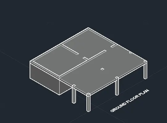
- Now, we have to create the floor for the first floor i.e the roof for the ground floor by using BOX command by providing dimension as per requirement.
- Or roof /slab can be provided by extruding a plane rectangular entity with the provided floor thickness
- For this go to the plan and choose the 3D floor layer and create a rectangle as per the inner dimension of the wall.
- Now using UNION command union all the walls and window/doors areas to make the single entity.
-
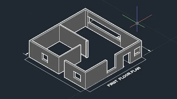
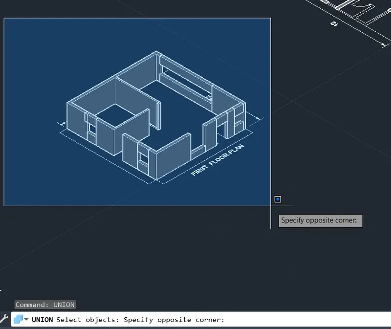
- Now, place the first floor above this by using MOVE/COPY command. ( Match the end points )
- Now, place the roof above the first floor.
- This is done in the same way as the one created for ground floor from the plan.
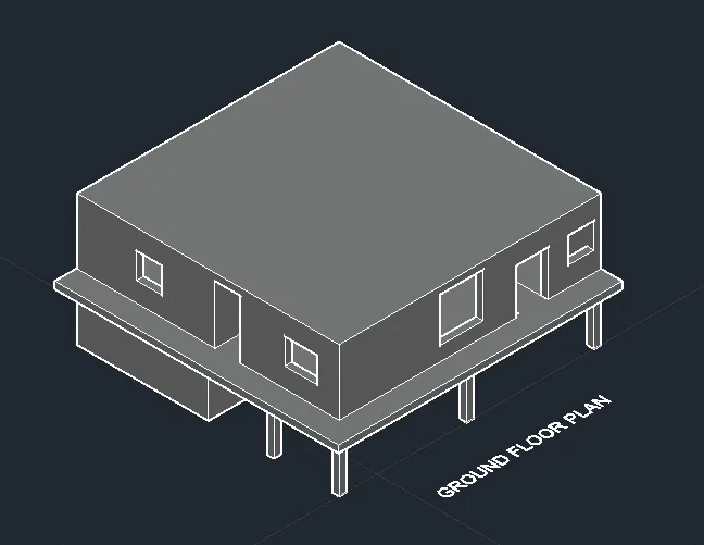
- This is done in the same way as the one created for ground floor from the plan.
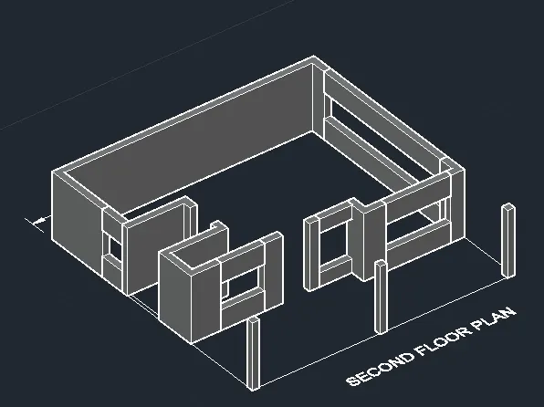
- Follow the same process for the Second Floor and alline all the floors
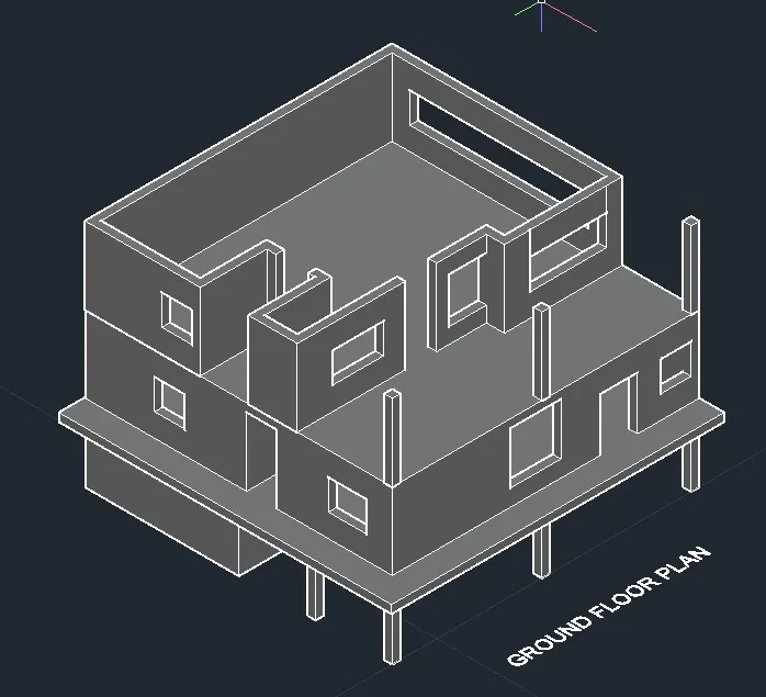
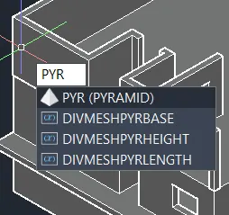
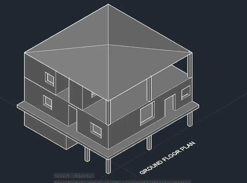
- The next we have to create the roof, here in this case Pyramid shape roof is provided by using PYRAMID command.
- This is also created from the plan or the slab provided in the previous plans can be copied.
- Now, create the windows and doors.
- For that go to elevation and copy the entire elevation beside it.
- Then in the copied elevation retain the doors and windows.
- Then change the layer to window frame and create a boundary region for the window frame.
- Then subtract the inner portion of the window.
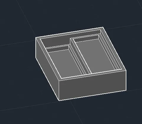
- Hence, windows and doors of the gound floor has been created.
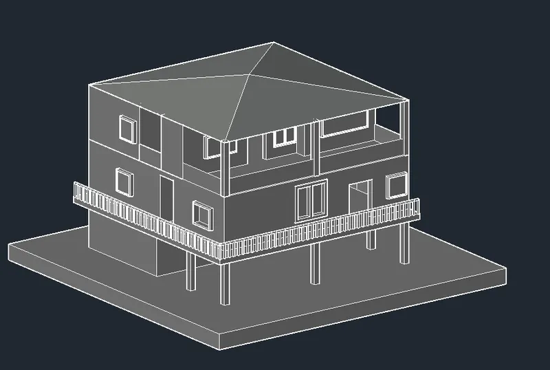
- Similarly, windows and doors of the first floor is also created which given below:
- The next step is to do the rendering, for this we have to position the camera so that better view is obtained and the view is named as camera1 and make it as realistic view.
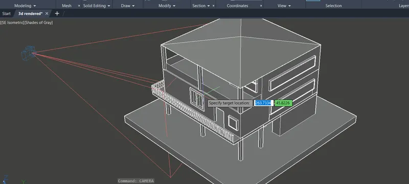
- Then change the view to the realistic, Now provide the MATERIAL for the liberary to the all parts of the 3D rendered House.
- Now Choose the Glass: Glazed to the windows and wood material to the window frames
- Now change the walls and floors material as per requirements.
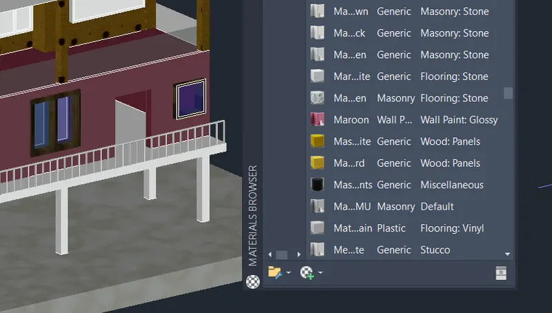
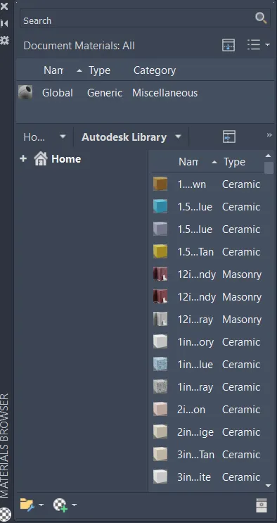
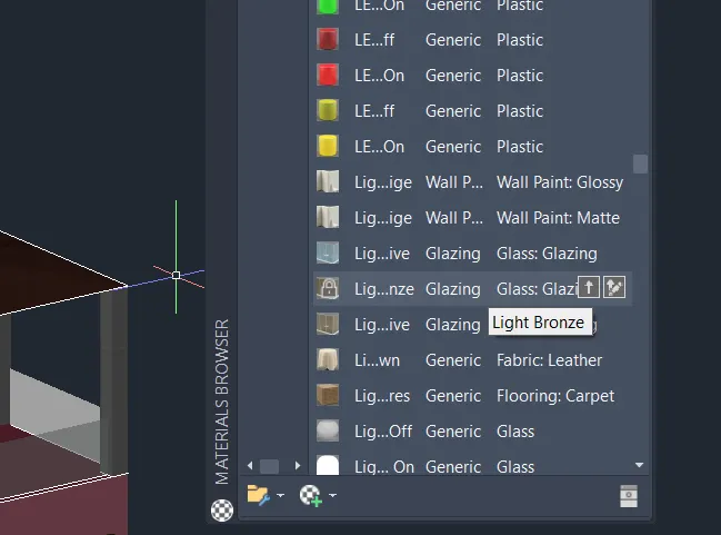
- After this, rendering process begins.
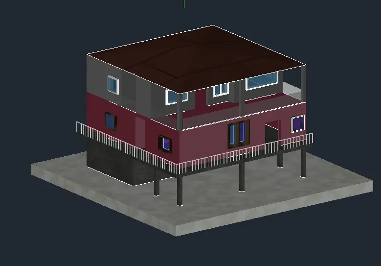
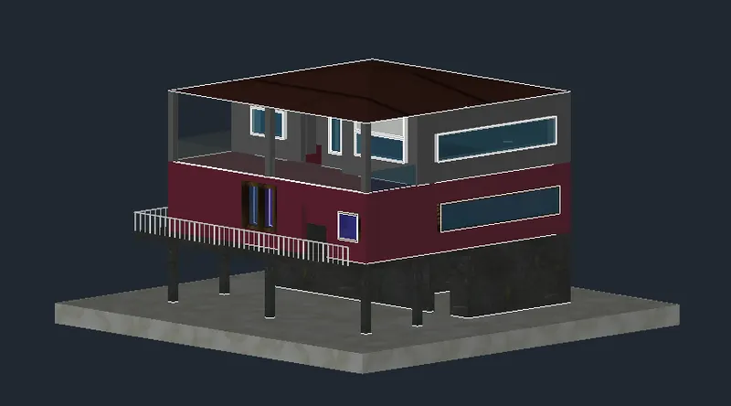
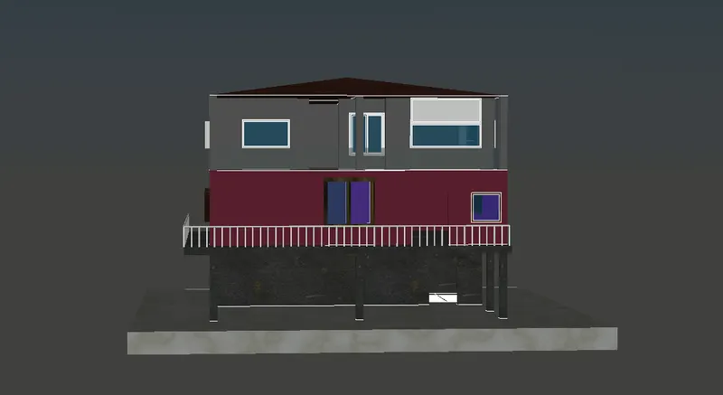
- The rendered image is obtained as given below:
RESULT :