Project 2_Creating a 3D rendered model for a Residential Building in AutoCad
AIM:
To create a 3 dimensional model of the residential building with a rendered view.
PROCEDURE:
Here,we create a 3 dimensional model of the residential building with a rendered view where we use AutoCAD Software to create it and here we use various Commands of AutoCAD while creating it.
The Commands we use are:
- RECTANGLE
- REGION
- EXTRUDE
- COPY
- UCS
And a few more when and where required.
- RECTANGLE:It is the Command to draw the rectangle.
- REGION:It is the Command used to create a region.
- EXTRUDE:It is the Command used to extrude a surface.
- COPY:It is the Command used to copy the objects.
- UCS:It is the Command used to adjust the coordinates.
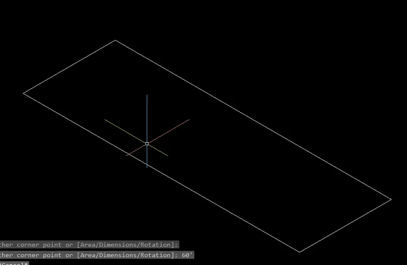
- Initially,we draw a rectangle using the RECTANGLE Command of the size 20' x 60'.
- Now,we create a surface using the REGION Command which is applied to the rectangle.
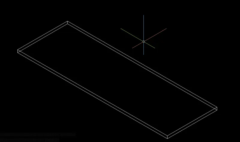
- After forming a surface,using the EXTRUDE Command we extrude the surface to a height of 6" such that it forms the base of the building as well as flooring too.
- Now,we copy the plan using the COPY Command above the base of the building.
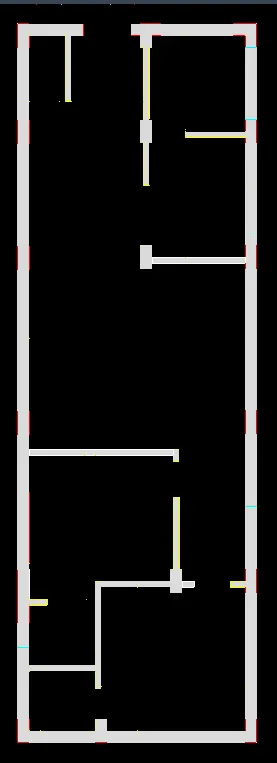
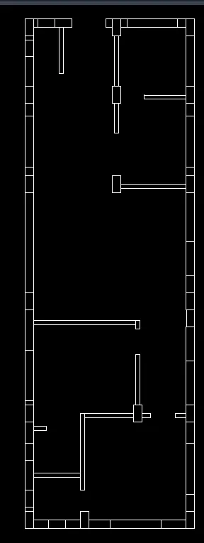
- Now,we create various regions such as for Windows,Walls,Columns,etc.
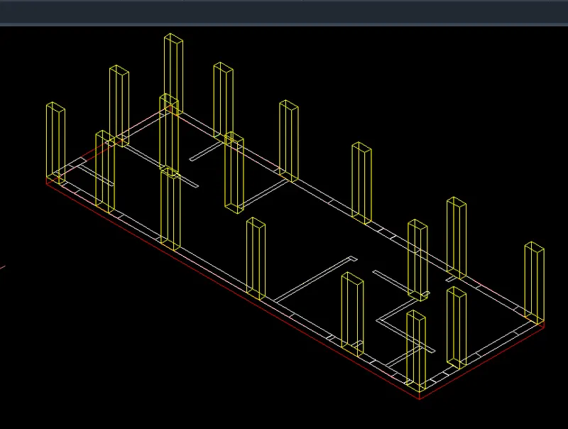
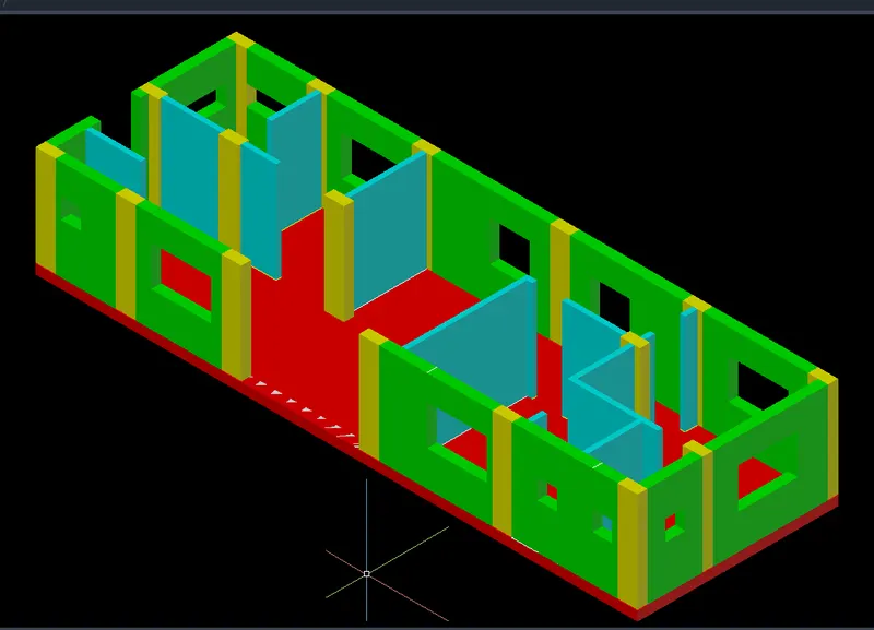
- After forming the various regions as specified,initially,we start creating the 3 dimensional view of the building by forming the Columns.
- Here,we raise the Column surfaces to a height of 10',such the Columns are formed.
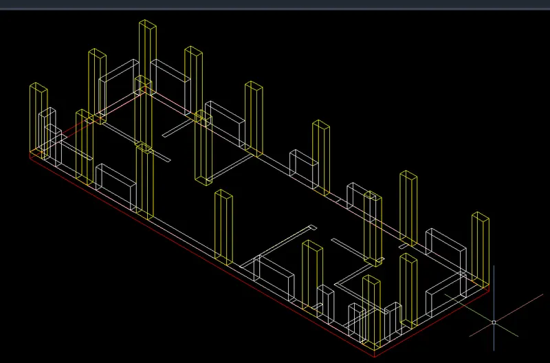
- After forming the Columns,we raise the wall below the Windows the sill level.
- For us to the raise the required surfaces to the required level,initially,we select the regions and then using the EXTRUDE Command to raise the surfaces to the required height.
- So,in this manner,when ever we raise the surfaces,we just select the regions created and then using the EXTRUDE Command,we raise to the required level.
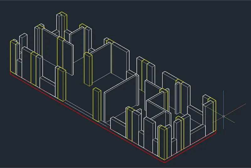
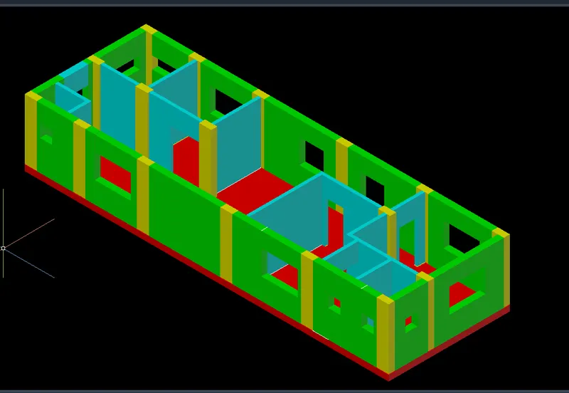
- After raising,the Walls below the Windows,we now raise the remaining part of the External and Internal Walls to the Slab level i.e.,10'.
- In this way,we get the Walls beside the Windows,so,basing upon these wall portions,we form the rectangles of the Window opening dimensions.
- After drawing these rectangles,we then form those as surfaces using the REGION Command.
- Which are then extruded downwards leaving the gaps for the Windows.
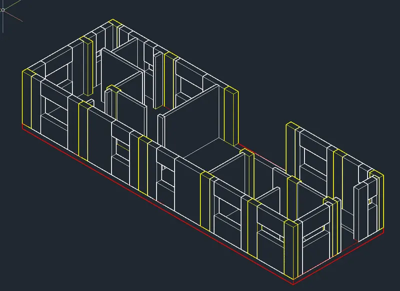
- In the similar manner,the rectangles are drawn using the RECTANGLE Command and the formed as surfaces using the REGION Command and then extruded downwards using the EXTRUDE Command to a depth of 3' such as form the gaps for the Doors.
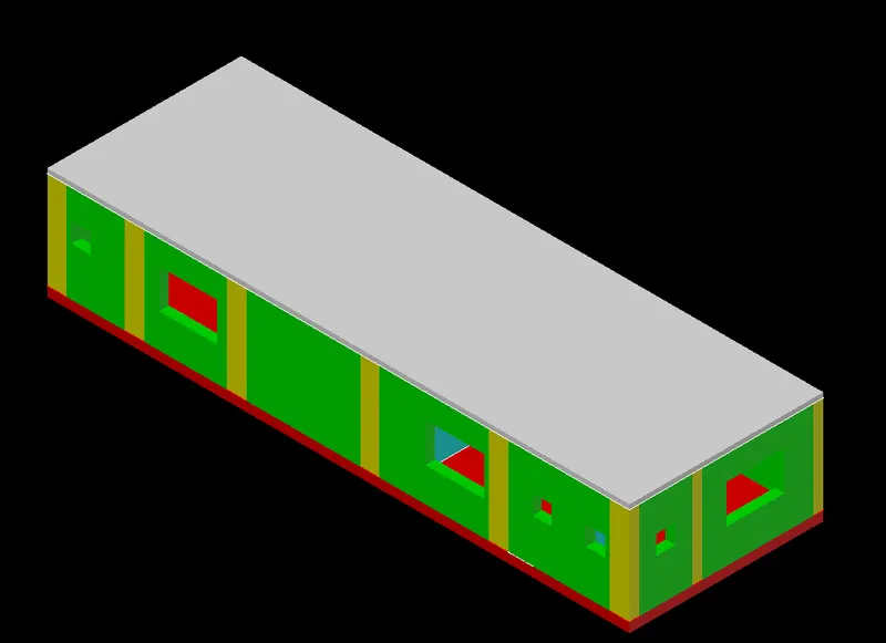
- Hence,after the required gaps for the Doors and Windows are formed,we draw a rectangle using the RECTANGLE Command above the Walls.
- Using the REGION Command,we form it as a surface.
- Using the EXTRUDE Command,we raise to a height of 6" such as forming the Slab.
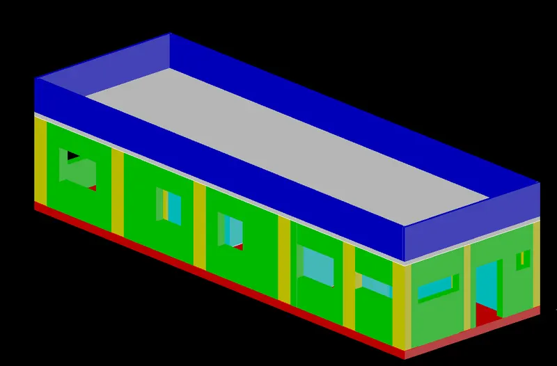
- In the similar manner,we even create the Parapet Walls,just using the UCS,RECTANGLE,REGION,EXTRUDE Commands.
- Here,using the UCS Command we select a proper face for drawing a rectangle using the RECTANGLE Command.
- And then,as known using the REGION Command we form the surface and then we extrude it using the EXTRUDE Command to the inner side to a thickness of 4".
- In this manner,we create the Parapet Walls on the remaining 3 sides.
RESULT:
Hence,the required 3 dimensional model of a residential building is formed.