Project 2_Creating a 3D rendered model for a Residential Building in AutoCad
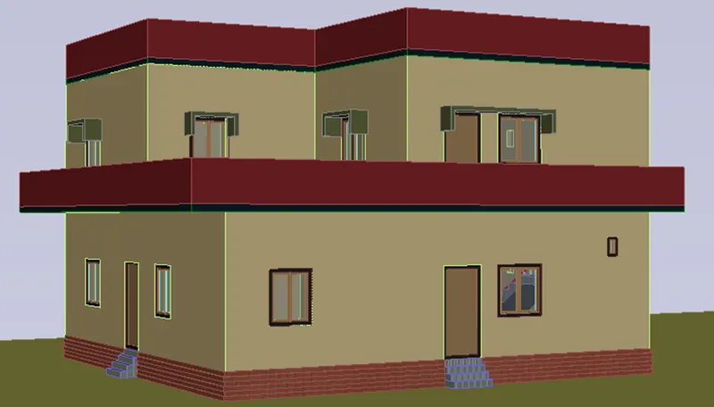
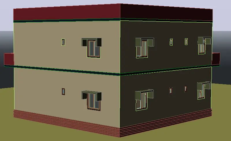
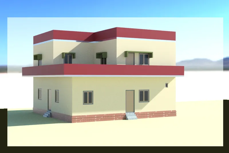
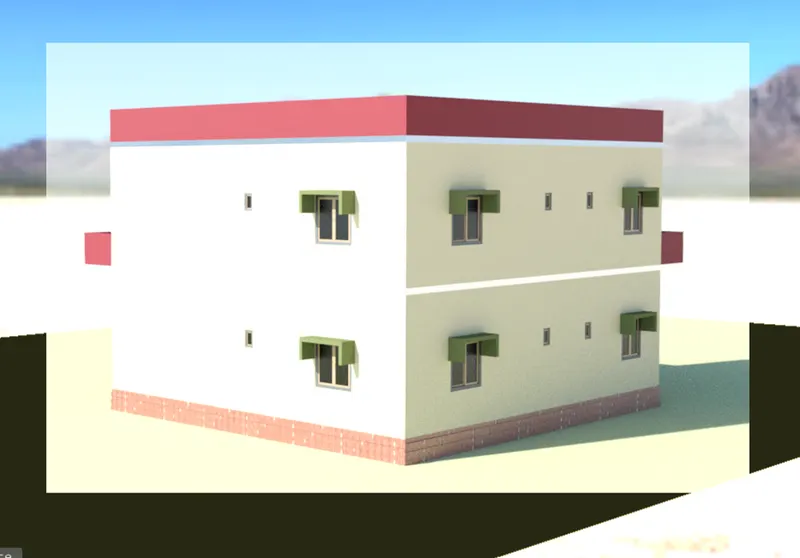
Create a 3-dimensional model of the residential building with a rendered view.
AIM:
To create a 3D model of the residential building with a render view.
Introduction:
The basic needs of human existences are food, clothing & shelter. From times immemorial man has been making efforts in improving their standard of living. The point of his effort has been to provide an economic and efficient shelter. The possession of shelter besides being a basic, used, gives a feeling of security, responsibility and shown the social status of man.
Every human being has an inherent liking foe a peaceful environment needed for his pleasant living, this object is achieved by having a place of living situated at the safe and convenient location, such a place for comfortable and pleasant living requires considered and kept in view.
- A peaceful environment
- Safety from all natural sources & climate conditions
- General facilities for community of his residential area
The engineer has to keep in mind the municipal condition, building bye law, environment, financial capacity, water supply, sewage provision of future, aeration, ventilation etc., in suggestion a particular type of plan to any client.
Dimensions of the residential building:
- Living room ground floor = 5600* 4500
- Living room first floor = 3900*4500
- Master bedroom ground floor & first floor = 4000*4000
- Bed room = 2500*4000
- Kitchen = 2500*4000
- Pooja room = 2500*1800
- Store room = 2500*1500
- Bathroom ground floor & first floor = 2000*2400
- Bathroom ground floor & first floor= 1500*2400
- Main door D = 1000*2000
- Other doors D1 = 900*2000
- Window W = 1200*1200
- Window W1 = 1000*1200
- Ventilator V = 450*300
- Thickness of waist slab & landing slab = 150mm
- Tread = 300mm
- Raiser = 180mm
- All columns are 230mm x 230mm
- All beams are 230mm x 300mm
- Slab thickness if 150mm
- The height of the wall is 3.3m
- The height of first floor wall is 3.3m
- Height of parapet wall is 0.9m
- Thickness of wall 230mm
- Thickness of partition wall is 150mm
PROCEDURE:
Step-1:
- First, we have to draw the plan of the residential building.
- To draw the ground floor plan, select the command RECTANG to draw the area of the building.
- Select the command OFFSET to draw the thickness of the external wall.
- Select the command EXPLODE to separate the rectangles.
- Take the command LINE and by using the direct distance entry method and draw the rooms.
- Select the command OFFSET to draw the thickness of the wall for every room.
- Select the command TRIM to give the openings for every room and also to eliminate the unwanted lines.
- Select the command LINE to draw the windows, ventilators and staircase for the building.
- Select the command OFFSET to draw the step for the staircase.
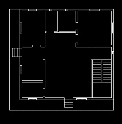
- After completing the ground floor plan, now we have to draw first floor plan by following the same procedure followed to draw the ground floor plan.
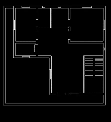
Step-2:
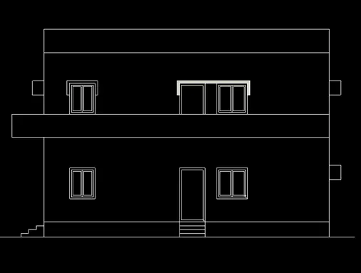
- After completing the plan of ground and first floor now we have to draw the elevation of the building.
- Select the command XLINE and draw the vertical and horizontal projection lines to draw the elevation.
- Select the command TRIM to eliminate the unwanted lines at lintel level, near windows and doors, at parapet wall and at sill level.
- Use the command OFFSET to complete the sketch of windows, sunshades and doors.
- Select the command LINE and command OFFSET to complete the drawing of steps.
Step-3:
- After completing the sketch of plan and elevation, now we have to draw the sketch of residential building in 3D.
- Now we have to create the layers for the doors, windows, sunshades, staircase, walls, parapet walls, floor etc.
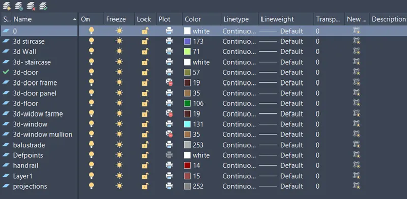
- Select the command COPY to copy the ground floor plan in another place.
- Select the command VIEWMAN to save the view for easy drawing
- Select the command BOUNDARY to create the plan as a region.
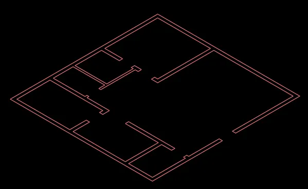
- Select the command EXTRUDE to raise the walls of the building to slab height.
- Select the command RECTANG to draw the rectangles at every window and at ventilator.
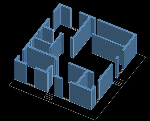
- Select the command BOUNDARY to create the windows and ventilator as region.
- Select the command EXTRUDE to raise the wall height at windows to sill level.
- Select the command UCS and place the UCS on the top of the wall for easy drawing.
- Select the command RECTANG to draw the rectangles at every window, door and at ventilator.
- Select the command BOUNDARY to create the windows, doors and ventilator as region.
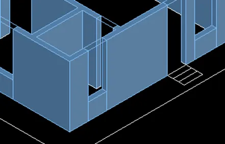
- Select the command EXTRUDE to raise the wall height at windows to lintel level.
- Select the command UNION to combine the external wall as single wall.
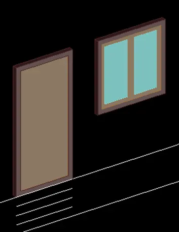
- Select the command COPY to copy the elevation in another place and use the command 3DROTATE to rotate the elevation in 90 degrees.
- Use the command BOUNDARY to create the region for window frame, window glass, door frame, door etc.
- Select the command EXTRUDE to draw the thickness for door frame, window frame, door and for window glass.
- Use the command MOVE to move the glass and door inside for complete the sketch of door and window.
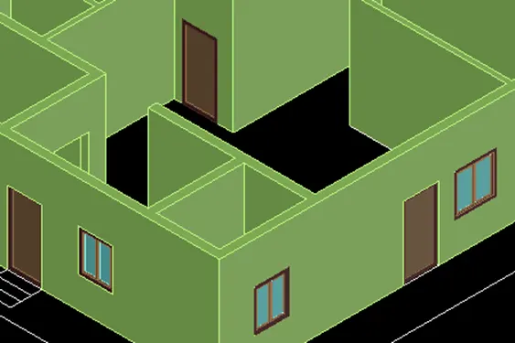
- After completing the sketch of door and window now we have to place the doors and windows in the building by select the command COPY.
- Select the command 3DROTATE to rotate the door and window for place them in outside and inside of the building by using the command
- After placing the doors and windows, now we have to draw the floor for the building.
- Use the command LAYOFF to hide the visibility of wall layer.
- Take the command RECTANG to draw the rectangle for entire plan.
- Select the command BOUNDARY to create the rectangle as region.
- Select the command EXTRUDE to raise the height from plinth level to ground level.
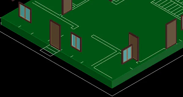
- Select the command SOLIDEDIT and select the face and copy the top face of the floor to another place and explode the face.
- Select the command ERASE to erase the region, then select the command UCS to place the UCS on required face for easy working.
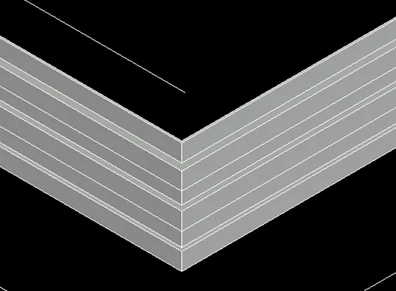
- Select the command RECTANG to draw the rectangle and also draw the small rectangles in it.
- Select the command BOUNDRY to create the region for design purpose for flooring.
- Select the command EXTRUDE and select the path for completing the design.
- Use the command MOVE to place it below the plinth level.
Step-4:
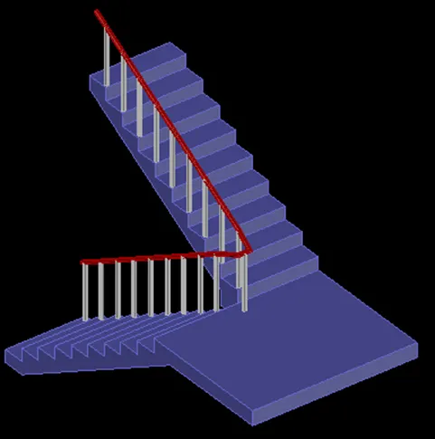
- After completing sketch of ground floor, now we have to draw the staircase.
- Select the command UCS to place the UCS on required face for easy working.
- Select the command PLINE to draw the steps having raiser and tread up to landing.
- Again, use the command UCS to place it on the last step to draw the landing.
- Select the command RECTANG to draw the rectangle for landing and use the command BOUNDARY to create it as a region.
- Use the command EXTRUDE to raise the height up to the thickness of landing.
- Again, use the command UCS place it on the top face f landing, to draw the continuation of steps.
- Select the command PLINE to draw the steps up to slab level or landing.
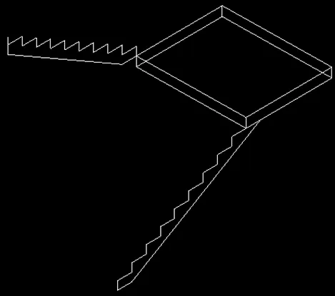
- Select the command EXTRUDE to extend the step up to required length in horizontal direction by creating them as region by using the command BOUNDARY.
- Pace the on the first step and draw the circle for balustrade and use the command COPY and place it every step and also on landing.
- Select the command PLINE to draw the line on the top of balustrade by connecting every balustrade.
- Use the command SWEEP to draw the handrail by using the circle and path as polyline on the top of balustrade.
- Apply the layers for the steps, balustrade and handrail.
- Use the command MOVE and place the staircase on required place on the ground floor.
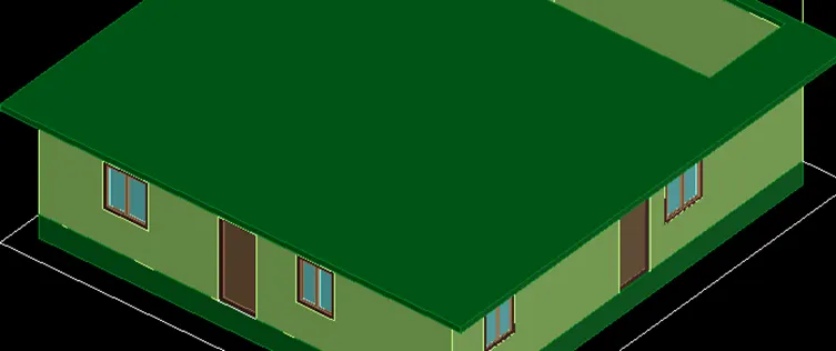
- Use the command RECTANG to draw the rectangle on the ground floor plan and create it as a region by using the command BOUNDARY.
- Use the command EXTRUDE to raise the slab level to height equal to thickness of slab.
Step-5:
- After completing the sketch of ground floor, now we have to draw the sketch of first floor.
- Select the command COPY to copy the first-floor plan in another place.
- Select the command BOUNDARY to create the plan as a region.
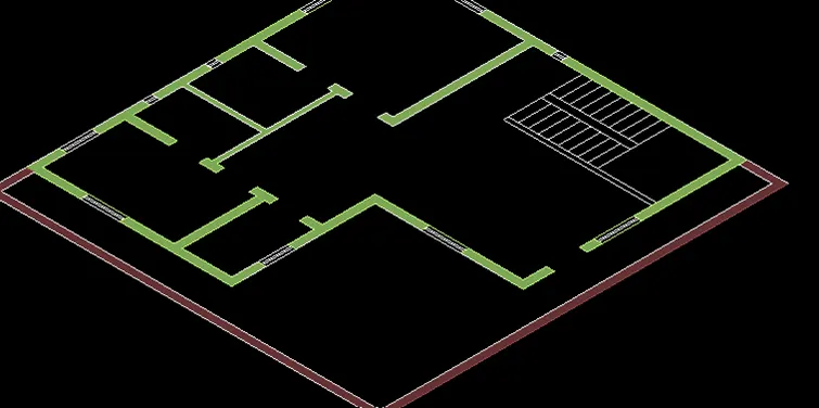
- Select the command EXTRUDE to raise the walls of the building to slab height.
- Select the command RECTANG to draw the rectangles at every window and at ventilator.
- Select the command BOUNDARY to create the windows and ventilator as region.
- Select the command EXTRUDE to raise the wall height at windows to sill level.
- Select the command UCS and place the UCS on the top of the wall for easy drawing.
- Select the command RECTANG to draw the rectangles at every window, door and at ventilator.
- Select the command BOUNDARY to create the windows, doors and ventilator as region.
- Select the command EXTRUDE to raise the wall height at windows to lintel level.
- Select the command UNION to combine the external wall as single wall.
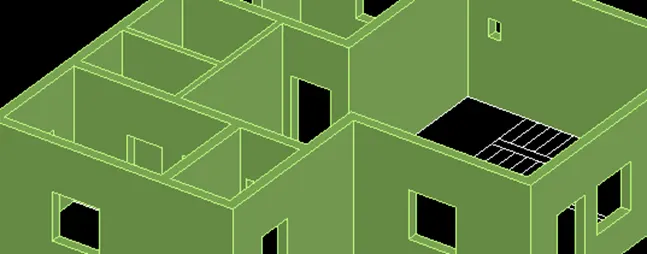
- After completing the placing of first floor sketch on the top of building, now we have to place the doors, windows, ventilators and sunshades in the building by select the command COPY.
- Select the command 3DROTATE to rotate the door, window, sunshades and ventilator for place them in outside and inside of the building by using the command
- Select the command EXTRUDE to extend the height of parapet wall up to required height.
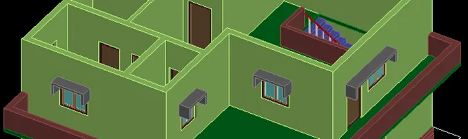
- Use the command UCS and place the UCS on the top of the building to draw the closed boundary by using the command PLINE.
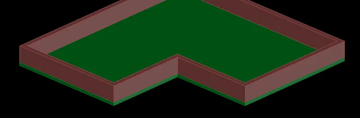
- Select the command BOUNDARY to create it as a region.
- Select the command EXTRUDE the slab and parapet wall up to the required height.
Step-6:
- After completing the sketch of isometric view of the residential building, now we have to create a render view for the sketch.
- Firstly, we have to create random views for the sketch and then we have to place the camera and distant light for lighting.
- Place the UCS on the floor and select the command CIRCLE and select the command EXTRUDE to elevate the circles at a specified height for camera and distant light.
- Select the command CAMERA and command DISTANTLIGHT place them on the required elevated circles.
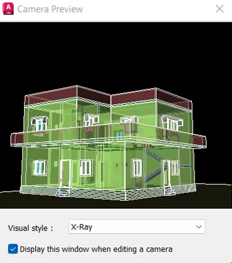
- After placing the camera and distant light over the sketch, now we have to give the materials for the sketch.
- Use the command MAT and select the AutoCAD library and select the wall painting and flooring etc, for complete the selection of materials for the sketch.
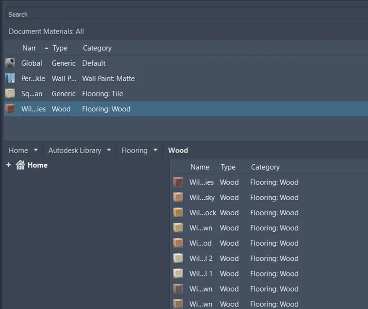
- After completing the selection of materials, we have to insert the paintings for decoration.
- For adjust the materials we can use the command MATERIAL MAPING to adjust them.
- In the RIBBON there is an option visualize and select the option render to modify the view as per the requirements.
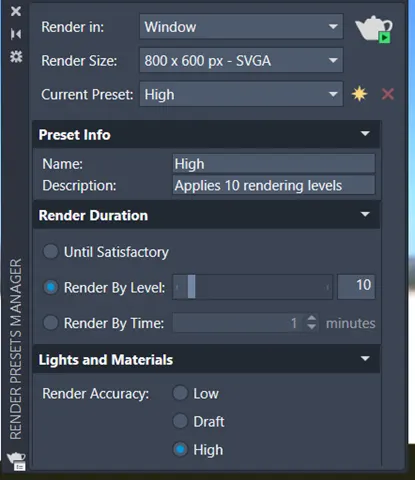
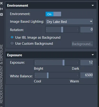
- Select the command RR to create a render view.
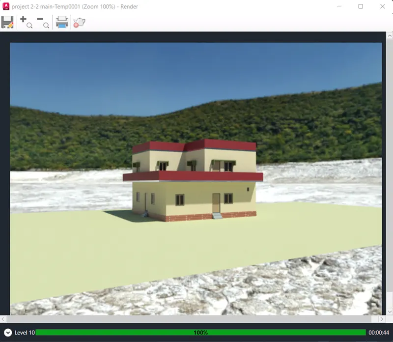
RESULT: