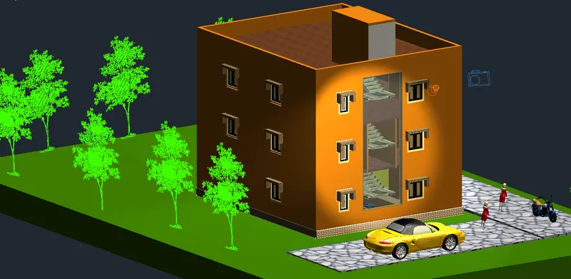
Project 2_Creating a 3D rendered model for a Residential Building in AutoCad
AIM:
To Create a 3D Isometric View RESIDENTIAL of the building with plan given.
INTRODUCTION:
Isometric drawing is a method of presenting the designs in three dimensional form. In order for
a design to appear threee dimensional, a 30 degree angle is applied to its sides.
Isometric drawings are helpful to show the design in 3D form during early stage of design development.
OBJECTIVE:
Draw the given isometric drawing in AUTOCAD using the iso-planes and isosnap. Apply
the hatch properties to distinguish the different surfaces and cross sections.
DRAFTING PROCEDURE:
1. Begin a new drawing file with imperial template.
2. Create standard border with the title block.
3. Create the necessary layers and text styles with different properties.
4. Create the iso-line referrences.
5. Create the isometric model using iso-lines in exploded form.
6. Apply different hatch patterns to distinguish the surfaces and cross sections.
7. Organize the various entities in the respectives layers.
8. Save the drawing file as Isometric_Drawing.dwg.
INTRODUCTION:
Autodesk's digital prototyping tools help engineers and designers experience their 3D
CAD desings virtually, before building the model. AutoCAD software provides advanced
3D modelling and design visulization tools that enable you to get a better understanding
of how a project will work before you build it.
AUTOCAD allow you to create the 3D models as a solid, a surface, or a mesh. The following
segment will explain you the GUI of 3D Modelling environment, various tools and technics used in 3D
Modelling using AutoCAD Software.
TYPES OF 3D MODELLING METHOD:
In AutoCAD VARIOUS TYPES OF 3D modelling technologies offer a different set of capabilities.
Wireframe modeling - is useful for initial design iterations and as reference geometry serving as a
3D framework for subsequent modelling.
Solid modelling - is efficient to use, easy to combine primitives and extruded profiles.
This offers mass properties and sectioning capabilities also.
Surface modelling - is useful in creating surface models, offers fine control over curved surface
for precise manipulation and analysis.
Mesh modelling - provides freeform sculpting, creasing, and smothing capabilities.
3D NAVIGATION TOOLS:
3D navigation tools allow you to view object in a drawing from different angles,
height, and distances. use the following 3D TOOLS to orbit, swivel, adjust distance zoom, and pan in a
3D view.
3D orbit - moves around a target. The target of the view stays stationary while the camera location,
or point of view, moves. The target point displays temporarily as a small, dark sphere. The method used
for location the target point is determined by the ORBITAUTOTARGET system variable.
CONSTRAINED ORBIT - Constrain 3D orbit along the XY Plane or the Z Axis.
FREE ORBIT - orbits in any directions without reference to the planes.
The point of view is not constrained along the XY plane of the z axis.
CONTINUOUS ORBIT - Orbits continuosly. Click and drag in the direction you want
the continuous orbit to move, and then release the mouse button. The orbit continues
to move in that direction.
ADJUST DISTANCE - Changes the distance of objects as you move the cursor vertically.
you can make objects appear larger or smaller, and you can adjust the distance.
SWIVEL - Simulates panning with a camera in the direction that you drag.
The target of the view changes.
you can make the objects the appears larger or smaller, and you can adjust the distance.
ZOOM - simulates moving the camera closer to an object or farther away. Zooming
in magnifies the image.
PAN - Starts the interactive 3D view and enables you to drag the view horizontally
and vertically.
USER coordinate system(USC):
The User COordinate System(USC) is a movable coordinate system, which is a fundamental tool
both for 2D drawing and 3D modelling.
The USC DEFINES:
- The XY plane also called the work plane, on which object are created and modified
- The horizontal and veritcal directions used for features like ORTHO mode, polar tracking, and object snap tracking
- The alignment and angle of the grid, hatch patterns, text, and dimension objects.
- The orgin and orientation for coordinate entry and absolute reference angles.
- For 3D operations, the orientation of work planes, projections planes, and the Z axis for for vertical direction and axis of rotation.
Ypu can change the location and orientation of the current USC by clicking
the USC icon and using its grips, or with the USC command. Display options for the USCICON
are available with the command.
UNDERSTAND the UCS IN 3D.
When you create or modify object in a 3D Environment, you can move and reorient the UCS anywhere in 3D Space to
simplify your work. The USC IS USEFUL for entering coordinates, creating 3D objects on 2D Work planes, and otating object
in 3D.
The UCS IN PAPER SPACE:
you can move and rotate the UCS IN paper space on a layout. However the UCS in paper space is restricted to 2D
Operations.
UNDERSTAND the world Coordinates System (WCS)
All objects in a drawing are defined by their coordinates in the World Coordinate System(WCS),
which cannot be moved or rotated. The WCS and the UCS are initially coincidient in new drawings.
UCS command
UCS command in used to set the orgin and orientation of the current user coordinate system(UCS).
The USC is a moveable CARTESIAN coordinate system that establishesthe XY work plane, horizontal and vertical
directions axes of rotation, and other useful geometric references. You can change the UCS origin and orientation for conveniences as you
specify points, enter coordinates, and work with drawing aids, such as ORTHO mode and the grid.
PROCEDURE TO ACCESS:
COMMAND: UCS and press enter.
options
Specify origin of USC - Defines a new UCS to a face on a 3D object. MOVE the cursor over a
face to preview how the UCS will be aligned
NAMED - Saves or restores named UCS definitions.
OBJECT - Aligns the UCS to a selected 2D OR 3D object. The UCS can be aligned
with any object type, including point clouds, expect xlines and 3D polylines.
PREVIOUS - Restores the previous UCS. You can steps back through the last 10 UCS Setting in the
current session.
VIEW - Aligns the XY plane of the UCS TO A PLANE PERPENDICULAR to your viewing direction.
The orgin point remains unchanged, but the X and Y axes become horizontal and vertical .
WORLD - Aligns the UCS with world coordinate system (WCS)
X,Y,Z - Rotates the current UCS about a specified axis.
you can define any UCS by specifying an origin and one or more rotations around the X,Y, and z axis.
Z Axis - Aligns the UCS to a specified positive Z Axis
SOLID MODELLING - USING NON PRIMITIVE FEATURES:
EXTRUDE COMMAND :
Extrude comand is used to create a 3D solid from an enclosed sketch, or a 3Dsurface from an
object. objects can be extruded orthogonally from the plane of the source object, in a specified direction,
or along a selected path. While using extrude command you can also specify a taper angle.
PROCEDURE TO ACCESS:
1. Command : EXTRUDE and press enter.
2. Ribbon menu : Home > Modelling > Extrude
options
objects to extrude - specifies the objects to extrude .
Mode - controls whether the extruded object is a solid or a surface.
Height of extrusion - Extrudes selected objects along the positive or negatives Z AXIS.
Direction - Specifies the length and direction of the extrusion with two specified points.
Path - Specifies the extrusion path based on the selected object.
Taper angle - specifies the taper angler for the extrusion.
Expression - Enter a formula or equations to specify the extrusion height.
LOFT COMMAND:
LOFT Command is used to create a 3d solid or surface feature by blending two different sections.
Creates a 3D solid or surface by specifies a series of cross sections.
The cross sections define the shape of the resulting solid or surface.
Procedure to access:
1. Command: LOFT and press
2. Ribbon menu: HOME> MODELLING > LOFT.
REVOLVE COMMAND:
REVLOVE command is used to create a 3D solid surface by sweeping a longitutinal section object
around an axis.
Open profiles creates surfaces and closed profiles can create either a solid or a surface.
SWEEP COMMAND:
SWEEP command is used to create a 3D solid or 3D surface by sweeping a 2D object
or sub object along an open or closed path. Open - ended objects create 3D surfaces, while objects that
enclose an area can be set to create either 3D solids or 3D surfaces.
Procedure to access:
1. Command : SWEEP and press enter.
2. Ribbon menu : HOME> MODELLING> SWEEP.
UNION COMMAND :
UNION command is used to combine two or more 3D solids, surfaces, or 2D regions into a single, composite 3D
solid, surface, or region
Procedure to access:
1. command : UNION AND PRESS ENTER
2. Ribbon menu: HOME> SOLID EDITING> UNION.
SUBTRACT command:
SUBSTRACT command is used to remove the portion of existing object using another interesting object.
procedure to access:
1. command : subtract and press enter.
2. Ribbon menu : HOME> SOLID EDITING> UNION.
3DORBIT COMMAND:
3DORBIT command is used to provide interactive viewing in 3D with the mouse.
Right click the mouse to display viewing options. 3DORBIT activates a 3D Orbit view in the
current viewport, and the 3DOrbit cursor icon appears.
You cannot edit objects while 3DORBIT is active. If you drag the cursor horizontally, the
camera moves parallel to the XY plane of the world coordinate system(WCS). If you drag
the cursor vertically, the camera moves along the Z axis. A small dark sphere displays temporarily,
representing the target point about which your view rotates.
PROCEDURE TO ACCESS:
Command: 3DORBIT and press enter.
options:
Constrained Orbit (press 1) - Constrains orbiting to the XY plane or the Z directions.
Free Orbit (press 2) - Allows orbiting in any direction, without being constrained to the XY plane or the z direction.
Continuous Orbit (Press 3) - changes the cursor to a sphere with two continuous lines enriching it and enables you to see
the objects into continuous motions.
Adjust Distance (press enter) - Simultates moving the camera closer to the object or father away.
Swivel - changes the cursor to an arched arrow and simulates the effect of swivelling the camera.
WALK
FLY
ZOOM
PAN.
3DROTATE COMMAND
In a 3D view, 3DROTATE command is used to display the 3D Rotate GIZMO to aid
in revolving 3D OBJECT around a base point.
With the 3D Rotate gizmo, you can drag to rotate selected object and sub objects freely or constrain
the rotation to an axis.
Procedure to access:
1. Command: 3DROTATE and press enter
2. Ribbon menu: Home> Modify>3DROTATE
3DMOVE COMMAND:
In a 3D VIEW, 3DMOVE command is used to display the 3D Move gizmo to aid in moving
3D OBJECTS a specfied directions. With the 3D Move gizmo, you can move selected objects
freely or constrains the movement to an axis or plane.
Procedure to access:
1. Command: 3D and press enter
2. Ribbon menu: Home> Modify> 3DMOVE.
Options:
Move along an axis - click an axis to constrain the movement to that axis.
Move along a plane - click the area between the axes to constrain the movement to that plane.
Stretch point - when you are specifying the move using gizmo, sets the new locations of the selected objects.
Drag and click to move yhe objects dynamically.
Copy - when you are specifying the move using the gizmo, creates a copy of the selected objects
instead of moving them. you can make multiple copies.
Base point: Specifies the base point of the 3D objects you want to move.
Displacement: Specifies a relative distance and direction for the placement of the selected 3D
objects using coordinated values that you enter at the command prompt.
CREATING THE NEW OBJECTS: IN 3D BASICS
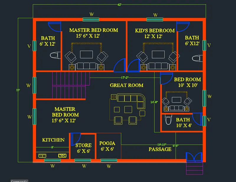
G+1 FLOOR PLAN :
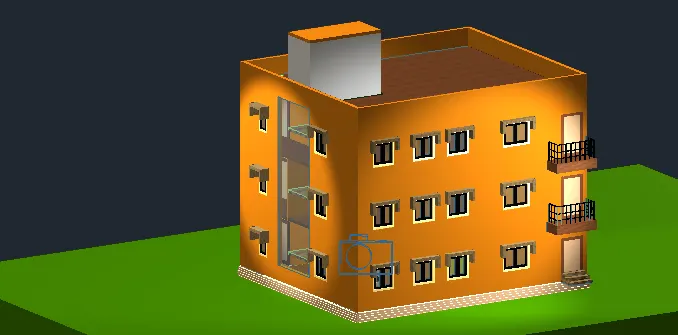
CAMERA FRONT VIEW:
CAMERA BACK VIEW:
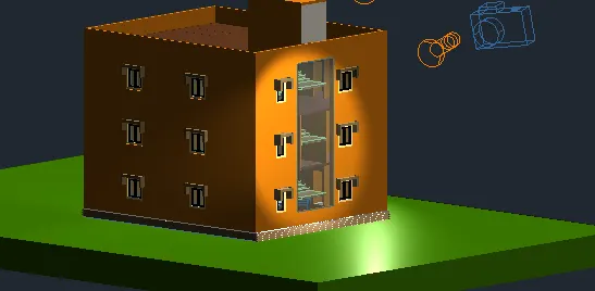
FULL FRONT RENDER VIEW :
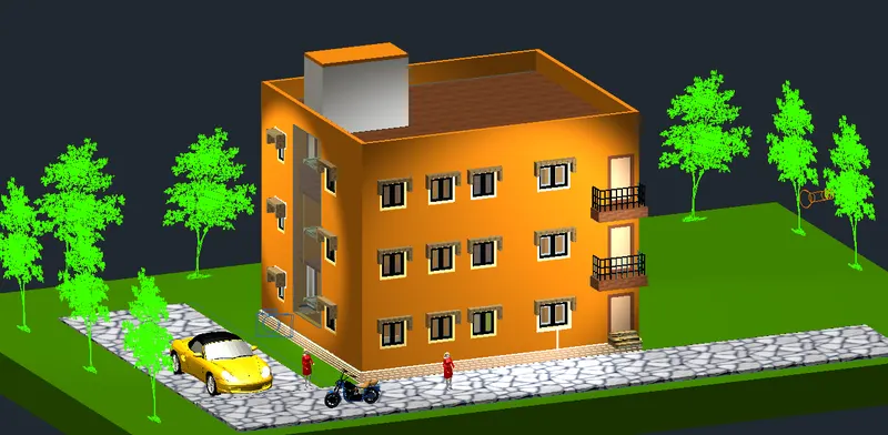
FULL BACK RENDER VIEW :