Creating a Floor plan, Footing detail and Isometric view using AutoCad
AIM : To create the given footing plan, footing detail and isometric view using AutoCAD.
Introduction: The main objective of this assignment is to get in touch with various tools in Auto Cad like rectangle, polylines, modification tools like copy, move etc. These tools will be understood by creating footing detail, two-bedroom building, cross section of 2-bedroom building showing foundation details and isometric view of steps and gable wall.
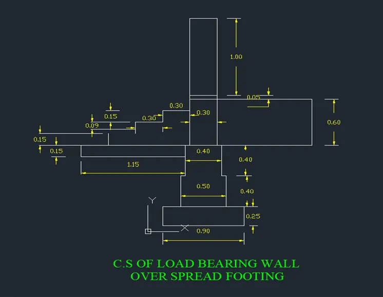
C1. Cross section of load bearing wall over spread footing:
Aim: To draw cross section of load bearing wall over spread footing using AutoCAD software.
Procedure:
- Open AutoCAD
- In the command box type QNEW
- Click on imperial, advance setup, decimal
- In the command box type units
- Select decimal, precision set to 0.00, angle set to decimal degree
- Type ds in the command box
- Snap spacing (x and y spacing) =0.5
- Grid spacing (x and y spacing) =0.5
- Create a rectangle by typing "REC" in the command box.
- Specify the first corner point.
- Click on dimension in the command box.
- Specify the length of rectangle=0.9 units in command box.
- Specify the width of rectangle=0.25 units in command box.
- Create another rectangle "REC" in the command box.
- Specify the first corner point which is 0.2 units from the starting point of first rectangle.
- Click on dimensions in command box.
- Specify the length of rectangle as 0.5 units.
- Specify the width of rectangle as 0.4 units.
- Create the third rectangle command "REC"
- Specify the first corner point 0.05 units from the corner of the second rectangle.
- Click on dimension in command box.
- Specify the length of rectangle as 0.4 units.
- Specify the width of rectangle as 0.4 units.
- Draw the line from the corner of third rectangle using command "L"
- Give the length as 1.15 units then move downwards and give value 0.15 units and then right and give length as 1.15 units.
- Create the fourth rectangle using command "REC"
- Specify the first corner point at a distance of 0.05 from the third rectangle
- Click on dimensions and give the length as 0.3 and width as 0.6 units.
- Now go to the point where we drew the line and at a distance of 0.3 draw another line giving distance of 0.15 units vertically and 0.3 units horizontally. Repeat till 3 steps are created.
- Draw another rectangle above fourth rectangle using command "REC"
- Specify the corner point as the corner point of fourth rectangle.
- Click on dimensions giving length as 0.3 units and width as 0.05 units.
- Draw the fifth rectangle using command -"REC"
- Specify the corner point as the corner of fourth rectangle.
- Click on dimension and give length as 0.3 units and width as 1units.
Result:
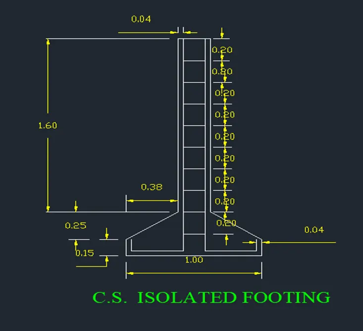
C2. Cross section of isolated footing
Aim: To draw Cross section of isolated footing using AutoCAD software.
Procedure:
- Open AutoCAD
- In the command box type QNEW
- Click on imperial, advance setup, decimal
- In the command box type units
- Select decimal, precision set to 0.00, angle set to decimal degree
- Type ds in the command box
- Snap spacing (x and y spacing) =0.5
- Grid spacing (x and y spacing) =0.5
- Draw line with command "l" and give 1units.
- L command and give the relative coordinates as @0,0.15
- Give the next coordinate as @0.38,0.25
- Next coordinate is @0,1.6
- Next coordinate @0.24,0
- Next coordinate @0, -1.6
- Next coordinate @0.38, -0.25
- Next coordinate @0, -0.15 or close.
- Now draw a line at a distance of 0.04 units from the top with line command
- Give value 0.04, then give the length of 1st line as 1.96.
- Next coordinate @-0.38,0 for the 2nd line
- Draw the third line, bend by giving the coordinate @0,0.06
- Copy the first line by command "co' click displacement and give value of 0.16 units.
- Copy the 2nd horizontal line by "co " specify base point and drag to the desired position.
- Copy the 3rd line by giving command "co" and select the base point and drag it.
- Give offset from top line with an offset distance of 0.2 units
- give command "o" and select the object giving offset distance as 0.2 and select multiple option for 9 such lines.
- trim the excess lines.
Result:
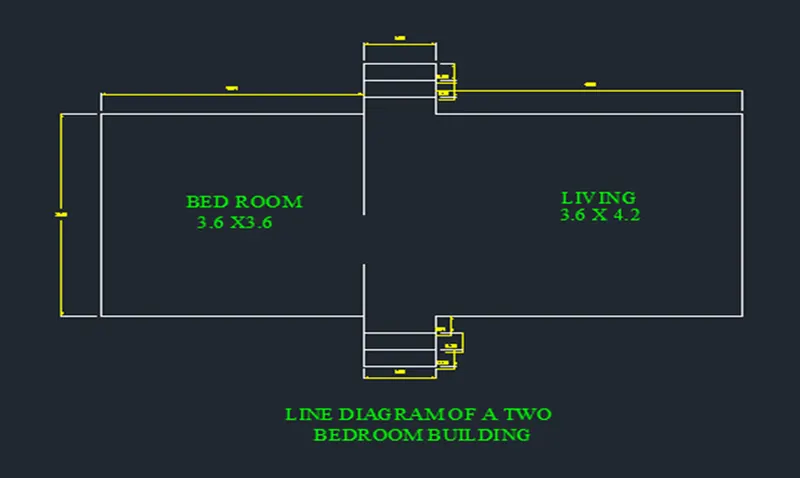
C3. Line diagram of a two-bedroom building
Aim: To draw line diagram of two-bedroom building using AutoCAD software.
Procedure:
- Open Auto Cad and type QNEW
- Click on imperial
- Set precision to 0.00, angle to decimal degree
- Type ds in command box
- Snap spacing (x and y spacing) =0.5
- Grid spacing (x and y spacing) =0.5
- Select polyline from ribbon and create bedroom of 3.6*3.6
- Command POLY and click a point then move the cursor towards south and give 0.9 units
- Now move the cursor to west and give 3.6 units
- Move to north and give distance of 3.6 units and then move to east and give 3.6 units and finally to south with 1.8 units
- The step outline is created using LINE tool
- Now from the corner point of 1.8 units draw a vertical line at a distance of 0.9 units
- Move the cursor to east and give distance of 1 unit
- Move to south with 0.9 unit
- Now draw living room is drawing using polyline also
- Give command POLY from the last point and then start the polyline
- Give 4.2 units in east
- Now move to south and go 3.6 units
- Move to west and go 3.6 units
- Create outline step again
- Specify command LINE select the last point drawn
- Move to south and go 0.9 units
- Move to west and go 1units
- Move to north and go 0.9 units
- Create the steps using offset with using command OFFSET and give 0.3 units distance by selecting object
- Click on multiple and move the cursor to the direction where it is to be drawn
- Repeat for other side also.
Result:
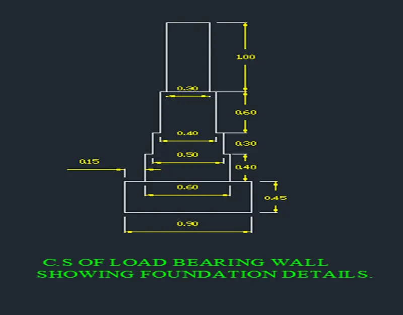
C4: Cross section of a load bearing wall showing foundation details
Aim: to draw cross section of a load bearing wall showing foundation details using AutoCAD software.
Procedure:
- Open Auto Cad and type QNEW
- Click on imperial
- Set precision to 0.00, angle to decimal degree
- Type ds in command box
- Snap spacing (x and y spacing) =0.5
- Grid spacing (x and y spacing) =0.5
- Create a rectangle by choosing RECTANGLE from ribbon
- Specify the dimensions- length= 0.9, width =0.45
- Select polyline from ribbon and specify first point 0.15unit from the corner of rectangle.
- With the cursor pointing north go 0.4 units
- Move east by going 0.05 units
- Move north by distance 0.3 units
- Move east by distance 0.05 units
- Move north by 0.6 units
- Move east by 0.4 units
- Move south by 0.6 units
- Move east by 0.05 units
- Move south by 0.3 units
- Move east by 0.05 units
- Move south by 0.4 units
- The top portion is drawn by polyline by select POLY from ribbon and give distance b0.05 units from the last point
- Move north by 1units
- Move east by 0.3 units
- Move south by 1units
Result:
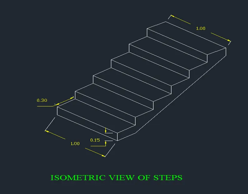
C5. Isometric view of steps
Aim: To draw the isometric view of steps using AutoCAD software.
Procedure:
- Open Auto Cad and type QNEW
- Click on imperial
- Set precision to 0.00, angle to decimal degree
- Type ds in command box
- Activate the isometric view from the toggle bar then snap off
- From isometric drafting select iso plane left
- Select line tool from ribbon and move towards west by 1units
- Move towards north by 0.15 units
- Move towards east and go 1 unit and south by 0.15 unit
- Change the isometric drafting to isoplane top
- Move the cursor to back and give 0.3 unit from the last drawn point
- Move to front and go 0.3 unit
- Change the isometric drafting to isoplane right
- Copy the object with ortho off
- Command 'co' and specify the base point and place it to new point and repeat for 4 steps
- With isoplane right draw a horizontal distance of 0.3 unit from starting point of stair
- Draw a vertical distance of 0.15 unit from the last stair.
- Join the two-point with ortho off and the stair is drawn.
Result:
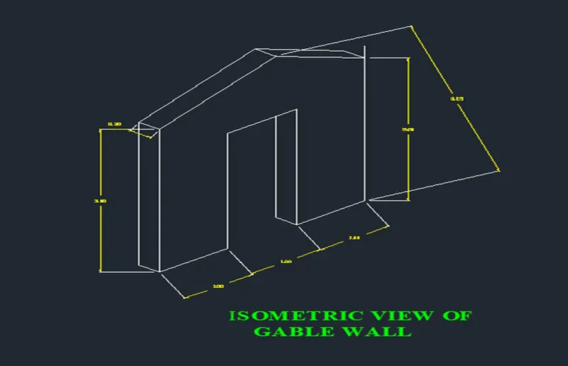
C6. Isometric view of Gable wall
Aim: To draw the isometric view of gable wall using AutoCAD software.
Procedure :
- Open Auto Cad and type QNEW
- Click on imperial
- Set precision to 0.00, angle to decimal degree
- Type ds in command box
- Activate the isometric view from the toggle bar then snap off
- Select line tool from ribbon and move cursor to left by 1 unit
- With cursor pointing upwards give 3 unit
- Draw 3 units to right and 3 units downward
- Select isoplane right then take line from ribbon and draw a line upwards 2.42 units from the starting point
- Draw 1 unit towards the right and 2.42 unit downwards
- Click on end point and close the figure
- Change to isoplane left and draw 0.3 unit as thickness on the left side
- Give the thickness of opening with isoplane left 0.3 units towards left and 2.12 units upwards
- Extend the thickness line of opening 1.13 units upward and 3.25 units from bottom
- With ortho off, draw the line between the corner of left side and the projected line done just before this step
- Draw it to other side also till it meets the right corner
- Draw the vertical line with ortho on to join the centre portion and erase the projected and horizontal lines
- Copy both the inclined lines and join the right end.
Result: