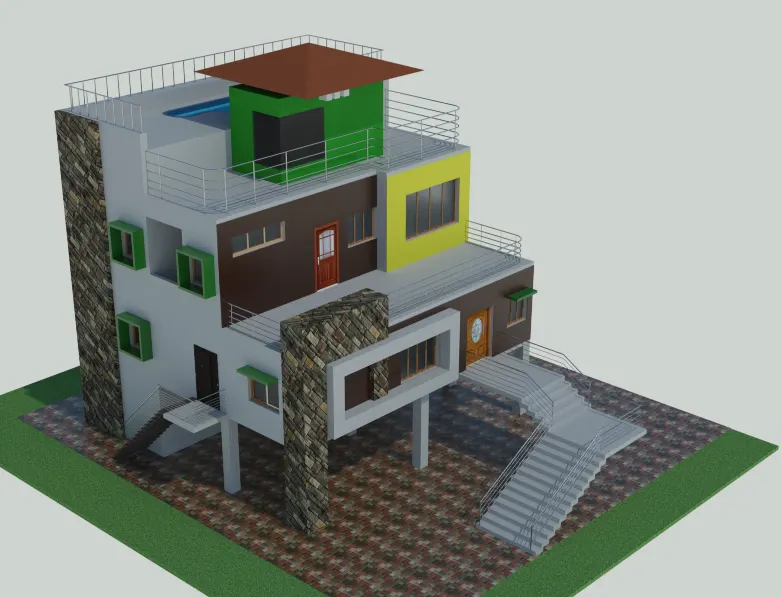
Project 2_Creating a 3D rendered model for a Residential Building in AutoCad
1):
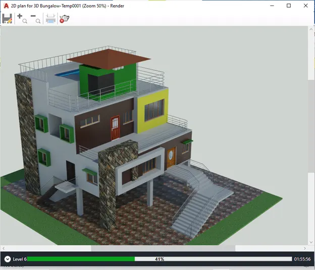
Aim: To create a 3 dimensional model of the residential building with a rendered view.
Introduction: To create a 3 dimensional model of the residential building with a rendered view
Procedure:
Step1:
- First set the units by using the command UN next set the limits as per the requirement of the drawing
- First we need to outer section a plan layout in 2d then we can go for 3d modeling
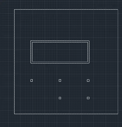
GROUND FLOOR PLAN:
- Take the rectangle command REC and draw a rectangle of 12mx4.6m
- Offset the rectangle to outer side give the offset unit as 0.4m
- To create the columns take the rectangle and draw the columns 0.4mx0.4m as shown
Step2:
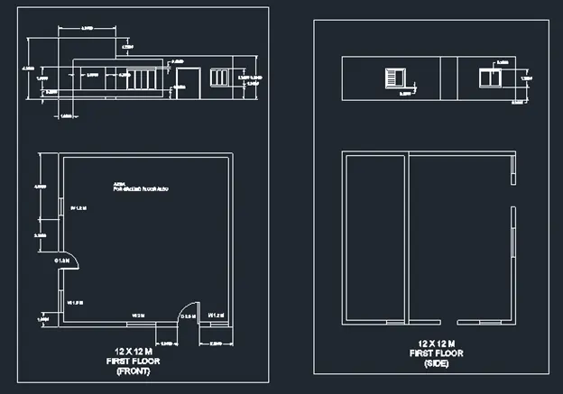
FRIST FLOOR PLAN:
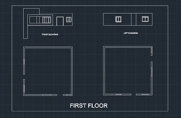
- Take the rec command and create a rectangle of 12mx12m including the area of ground floor and take the offset command and give the offset of 0.42m
- Creating of windows all the windows is taken of 3.6mx3.6m
- Opining for the main door is taken as 1.5m and opining for the side door is taken as 1.2m
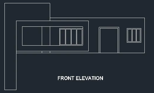
CREATING OF ELEVATION:
- Take the reference lines from the plan for the opining of windows and doors
- Take the height of the floor as 3m and sill height for the windows is taken as 0.9m and windows size is 1.2mx1.2m and give height of the door is 2.2m
- Providing the dimensions the command DIML select the first point and last point and place the position.
Step3:
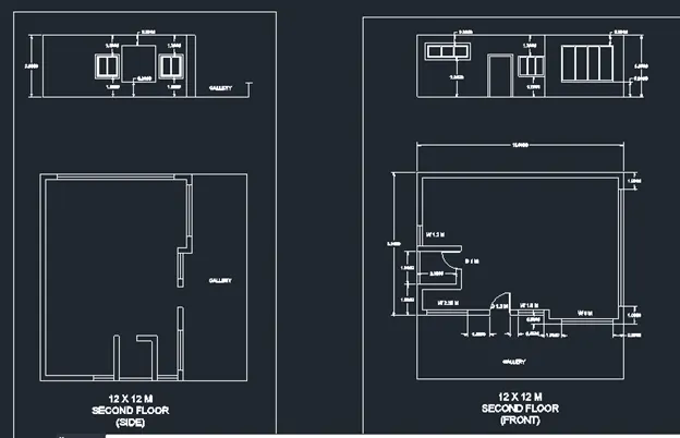
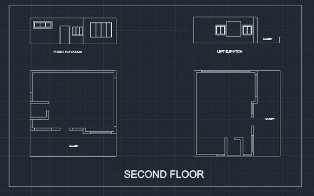
SECOND FLOOR PLAN:
- Take the rec command and create a rectangle of 12mx12m including and take the offset command and give the offset of 0.42m
- Creating of windows all the windows is taken of 3.6mx3.6m
- Opining for the main door is taken as 1m and opining for the side door is taken as 1m
CREATING OF ELEVATION:
- Take the reference lines from the plan for the opining of windows and doors
- Take the height of the floor as 3m and sill height for the windows is taken as 0.9m and windows size is 1.2mx1.2m and give height of the door is 2.2m
- Providing the dimensions the command DIML select the first point and last point and place the position.
Step4:
- Now change the work space to 3D modeling and set the view as SW isometric
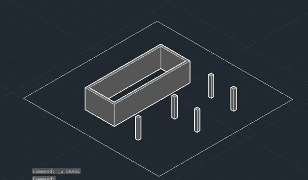
- Take the copy of ground floor plan and create the 3D object
- Take the command presspull and keep the cursor in close boundary region and give the height as 3m for ground floor wall and columns
Step5:
CREATION OF SLAB
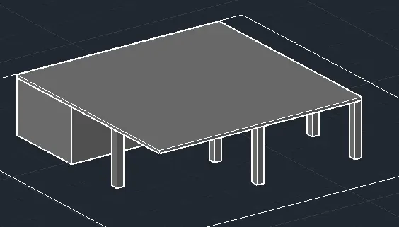
- From the ribbon take the box and draw a rectangle from the select the first point and second point and give the height as 1.5m
Step6:
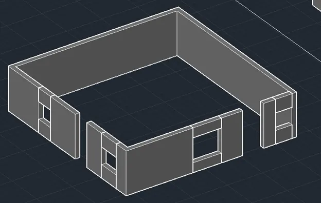
- Creating the walls for the first floor plan
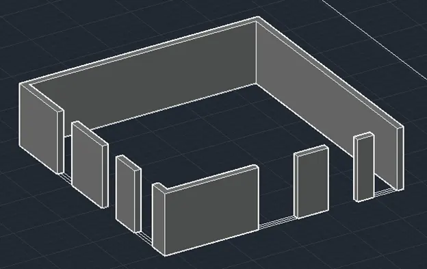
- Take the copy of first floor plan and create the 3D object
- Take the command presspull and keep the cursor in close boundary region and give the height as 3m for all the walls
Step7:
CREATING THE OPINING FOR THE WINDOWS AND DOORS
- Take the command presspull keep the cursor in close boundary region and give the window sill height as 1.2m
- Next copy the select the base point and place it at the end point of the wall
Step8:
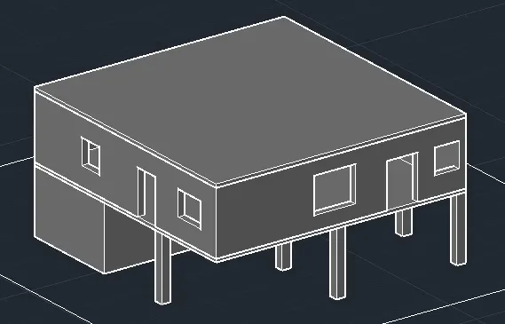
- Select the union from the from the ribbon > solid editing > union select the object enter
- Now take the copy command select the object give the base point and place at the top of ground floor
- Copy the slab of ground floor and place it at top of first floor
Step9:
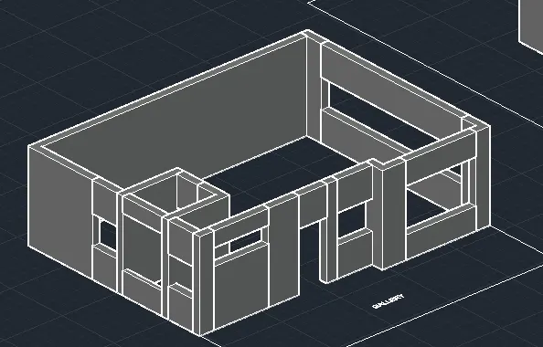
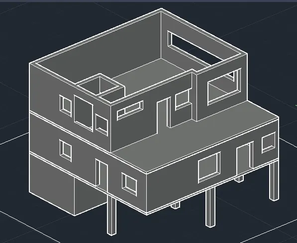
- Creating the walls for the second floor plan
- Take the copy of first floor plan and create the 3D object
- Take the command presspull and keep the cursor in close boundary region and give the height as 3m for all the walls
Step10:
CREATING THE OPINING FOR THE WINDOWS AND DOORS
- Take the command presspull keep the cursor in close boundary region and give the window sill height as 1.2m
- Next copy the select the base point and place it at the end point of the wall
Step11:
- Select the union from the from the ribbon > solid editing > union select the object enter
- Now take the copy command select the object give the base point and place at the top of first floor
Step12:
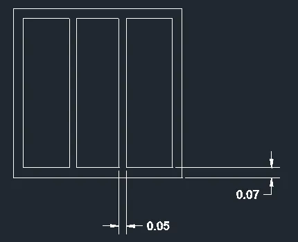
CREATING ALL THE WINDOWS FRAME AND GLASS:
- First create the window in 2D with frame and we can easily develop in 3D
Step13:
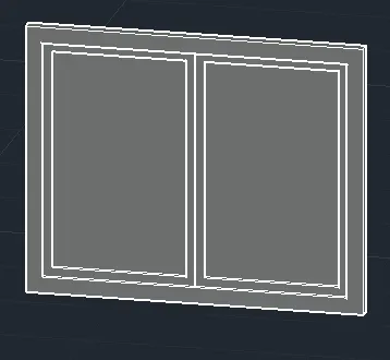
- Take the command presspull keep the cursor in close boundary region and give the window frame give height 0.03 and glass height 0.01
Step14:
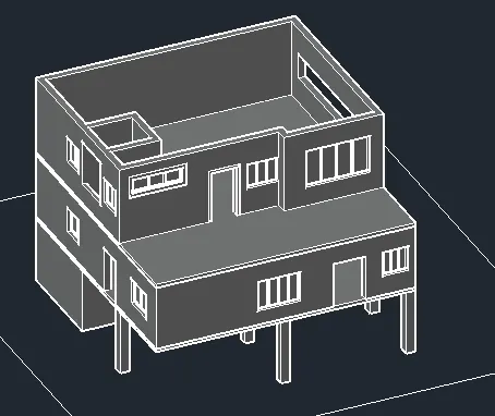
- Now take the 3D rotated command and rotated the window at 90 degree
- Take the copy command give the base point as mid point of the window and place it at midpoint of window wall
Step15:
CREATION OF ELEVATIONS:
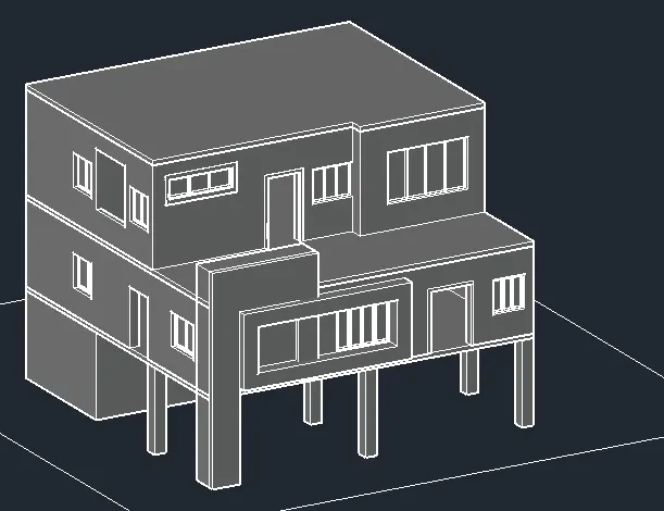
- Copy the 2D elevation and take the presspull command give the height for the elevation and take the rotated command and rotated at 90 degree now take the move command give the base point and place the object as position as shown
Step16:
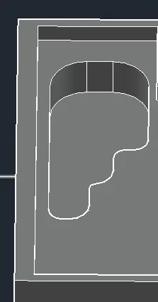
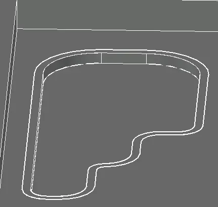
CREATING SWIMMING POOL AND HEAD ROOM AT TOP OF THE BUILDING:
- Take the PL and create a parapet wall of height at 0.6m for the swimming pool
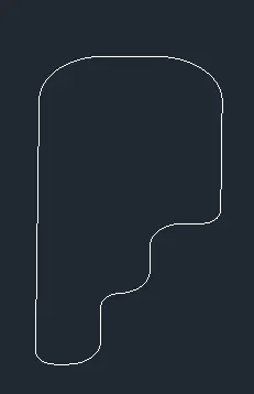
- Take the command PL for the poly line and create the shape of the swimming pool as shown
- Next the fillet command give the radius as 1m for the end point and 0.3m for edges as shown
- now take the offset command and offset the 0.15M
- Next the presspull command at the bottom side take the 1.3m as shown
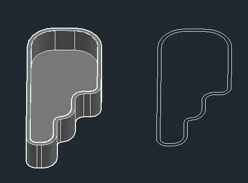
- now take the move command select the midpoint and place the above of the 2nd floor slab the depth for the swimming pool is created as shown
Step17:
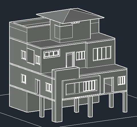
- Creating a headroom at top of building
- Draw a rectangle at the face of solid and take the presspull command and give the height of the wall as 3m
- For the roof take the pyramid from the home modeling select the midpoint and give the height as 0.05m as shown
Step18:
CREATING OF RAILINGS:
- Take the PL and create a line and take the move command and move at an height of 0.9m
- Now take the filter command and give the radius of 0.05
- Now draw a circle of 0.02m at the face of solid surface and take the sweep command and select the object as shown
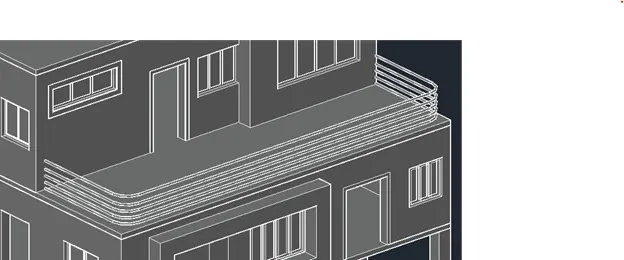
- Similarly create all the railings of the building
Step19:
CREATING OF STAIRECASE:
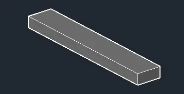
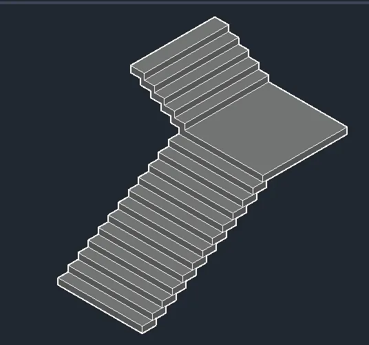
- Take the box give the first point width of the staircase is taken as 0.04m and length is 2.3m riser height is given as 0.175m
- Now take the copy command give the base point and place the staircase ine above the other
- At the last step take the presspull and give the mid landing length as 3m as shown
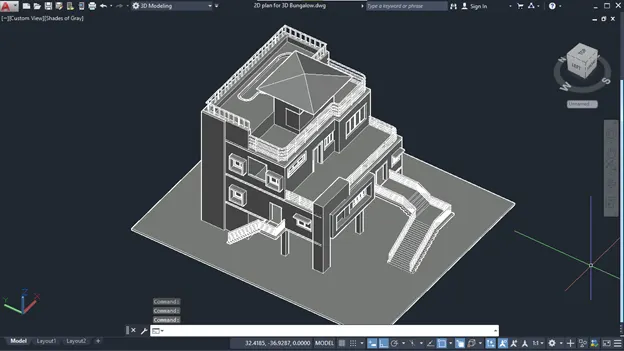
- Next take the move command select the midpoint and place at the door point as shown
Step20:
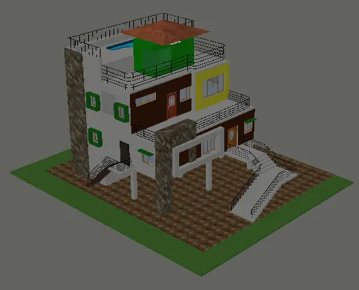
- Now take the command “mat” for assign the property to the objects
- Take the colour for walls and give metallic property for railing
- While assign the property to object keep the view in realistic
Step21:
- CREATING RENDERED VIEW:
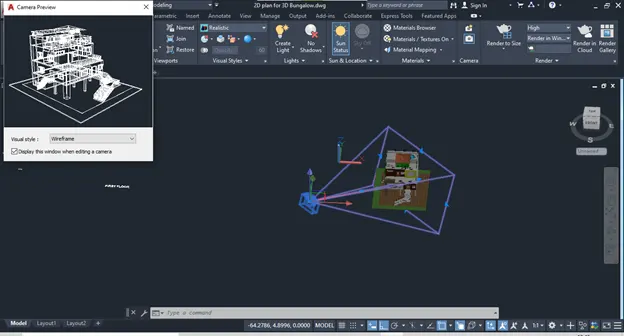
- From the ribbon go visualize > camera > create the camera view
- Take the environment setting keep the sun light on and allow the shadow etc.
- Now do render option give the required quality rendering
Result: