Creating a Floor plan, Footing detail and Isometric view using AutoCad
Aim: To draw the cross section of load bearing wall over spread footing
Introduction: To draw the cross section of load bearing wall over spread footing
by using Autocad .
procedure:
step1:
create a rectangle type REC in command box
- specify the first point
- specify the width of the rectangle 0.9 in the command box
- specify the length of the rectangle 0.25 in the command box
Step2
Create a line type LINE in command
Take the distance of 0.2 from the left side and create line in y axis of length 0.4
Take the distance of 0.2 from the right side and create line in y axis of length 0.4
The distance between the both line is 0.5
Step 3
Take the line command from the command box
Take the distance of 0.05 from left side and 0.05 distance from the right side
Cerate a line of length 0.4 in y axis
Step 4
Take the line command from the command box
Take the distance of 0.05 from left side and 0.05 distance from the right side
Cerate a line of length 0.4 in y axis
Close the line with the distance of 0.3
Step 5
Take the line command from the command box
Take the distance of 0.15 in -ve y axis
Take the distance of 1.15 in -x axis
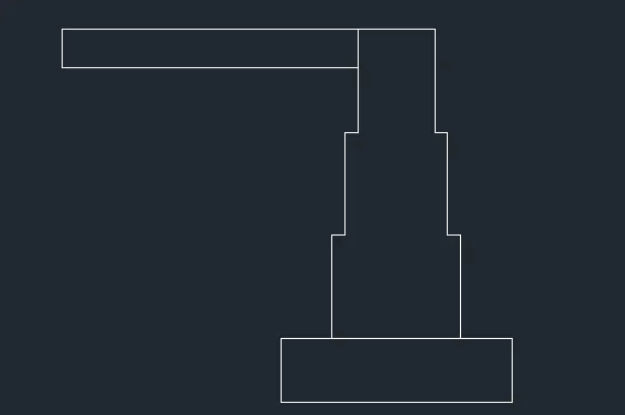
Step 6
Take the line command from the command box
Make the line of length of 0.6 in the y axis from the both side
Join the above line with the distance of 0.3
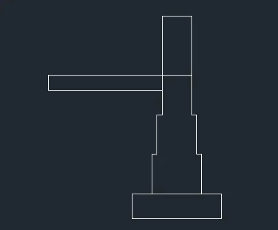
Step 7
Take the line command from the command box
Take the dist of 0.30 in x- axis and 0.15 in y- axis
Similarly make the three steps
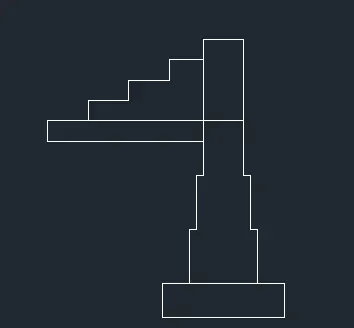
Step 8
Take the line command from the command box
take the distance of 0.05 in y axis
take the distance of 1.0 in y axis
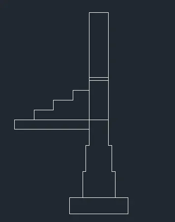
Result:
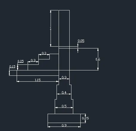
2):
Aim: To draw C.S isolated footing
Introduction: To draw C.S isolated footing by using AutoCad
Procedure:
Step1
- Take the line by typing L in the command box
- Draw a line with the unit 1
- Take the line and make the vertical line in with the unit 0.15 at the both end point of the line
- Take the line command draw a line with unit 0.38,0.25 and -0.38,0.25
- Take the line command draw a line with unit of 1.60 in y direction from both the end point
- Take the line command and join the top points
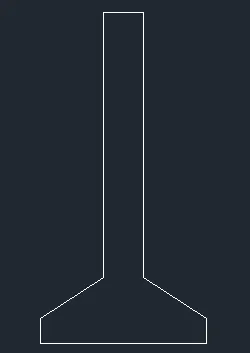
Step2
- Take the offset by typing o in the command box
- Take the offset unit 0.04 and select the object
- Next extend the to bottom
- Take the trim command from the command by typing tr
- Next trim the extra lines
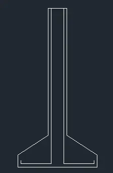
Step3
- Take the offset by typing o in the command box
- Take the offset unit 0.20 and select the object
- Select and draw the multiple line
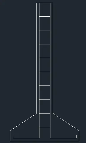
Result:
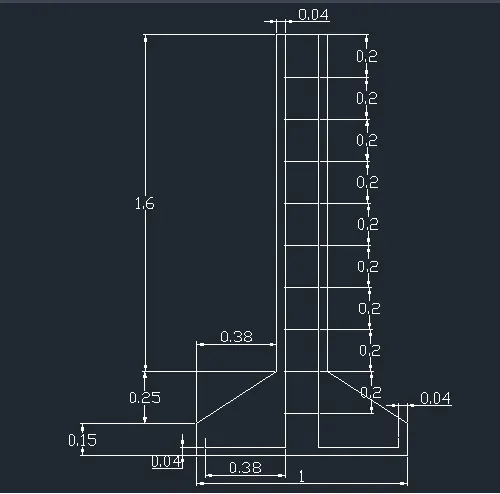
3):
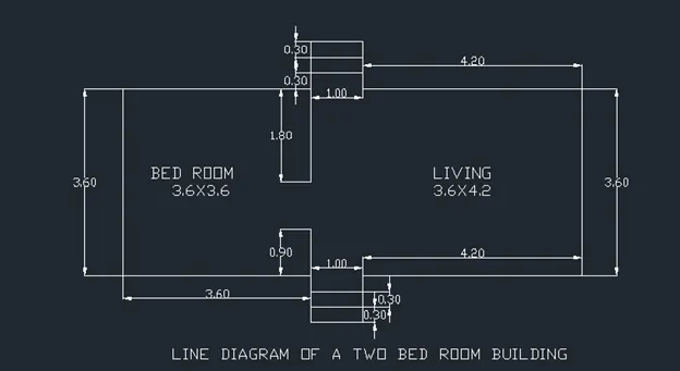
Aim: To create a line diagram of two building
Introduction: To create a line diagram of two building by using autocad
Procedure:
Step1
Take a line by typing L in command box
Create a line in x axis with the unit 3.60 and in y axis 3.60
Take the line command and create line in -y axis with unit 1.80
Take the line command and create line in +y axis with unit 0.90
Step2
Take a line by typing L in command box
Create a line in y axis with the length of 0.90
Next create a line in x axis with the length of 1.0
Take the offset of 0.30 two times
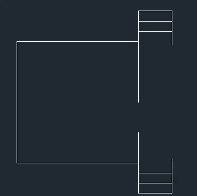
Step3
Take a line by typing L in command box
Create line in x direction with length of 4.20
Next create a line in y direction with the length of 3.60
Next close the line at end point
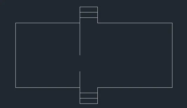
Result:
4):
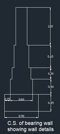
Aim: C.S. of bearing wall showing foundation details
Introduction: C.S. of bearing wall showing foundation details by using AutoCad
Procedure:
Step1:
- create a rectangle by typing REC in command box
- Create a rectangle of 0.90,0.45
Step2:
- Take a line command and mark a distance of 0.15
- Next create a line with unit of 0.40 in y axis on both sides
Step3:
- Take a line command and mark a distance of 0.05
- Next create a line with unit of 0.30 in y axis on both sides
Step4:
- Take a line command and mark a distance of 0.05
- Next create a line with unit of 0.60 in y axis on both sides
Step5:
- Take a line command and mark a distance of 0.05
- Next create a line with unit of 1.0 in y axis on both sides
Result:
5):
Aim: To draw the isometric view of steps
Introduction: To draw the isometric view of steps by using AutoCad
Procedure:
Type a command “DS” in command box
Keep the isometric snap on, and off the grid off, snap off
Make sure that ortho mode is on
Step1
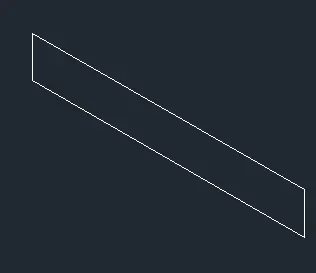
- From the isometric drafting select the left isoplane
- Take the line command and create a line of 1 unit
- Create a vertical of unit 0.15 from the both end point of the line
- Move the cursor to x axis and join the line
Step2:
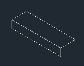
- Change the isoplane to top
- Take the cursor to last point and give the unit 0.3 at the both end point
- Next join the both end points with the unit of 1.0
Step3:
- Change the isoplane to right
- Take the copy command by typing CO in command box
- Select the object specify the base point take to new point
- Repeat the 4 steps
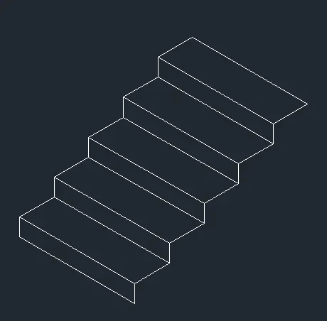
Step5:
- Copy the horizontal distance 0.3 at staring end of the step
- Copy the vertical distance 0.15 at last end of the step
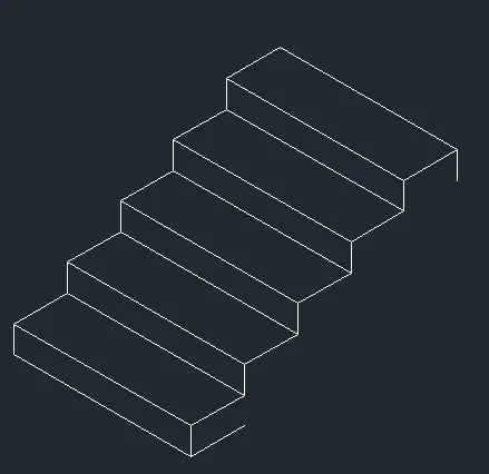
Step6:
- Take the line command by typing L in the command box
- Join the two end points with the help of line
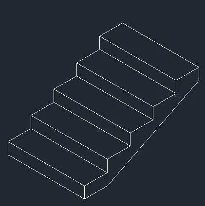
Result:
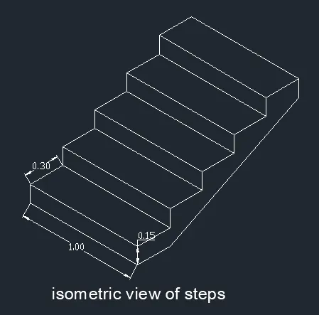
6):
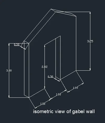
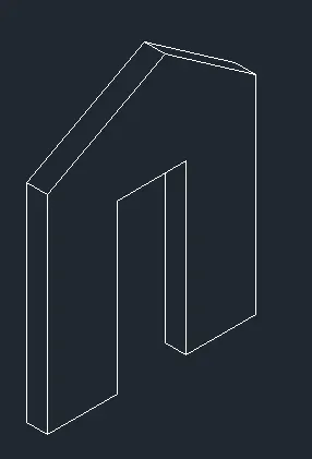
Aim: To draw the isometric view of gabel wall
Introduction: To draw the isometric view of gable wall by using AutoCad
Procedure:
Type a command “DS” in command box
Keep the isometric snap on, and off the grid off, snap off
Make sure that ortho mode is on
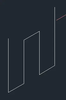
Step1
- From the isometric drafting select the right isoplane
- Take the line command and create a line of 1 unit
- Take the cursor to y axis create a line with 2.42 unit
- Take the cursor to -x axis with the unit 1
- Take the cursor to -y axis create a line with 2.42 unit
- Take the cursor to -x axis with the unit 1
- Next take the cursor to left and create a line unit of 3.0
- Next take the cursor to right and create a line unit of 3.25
Step2:
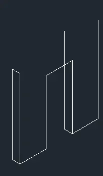
- From the isometric drafting select the top isoplane
- Next create the width of unit 0.30
- From the isometric drafting select the right isoplane
- Next take the cursor to left and create a line unit of 3.0
Step3:
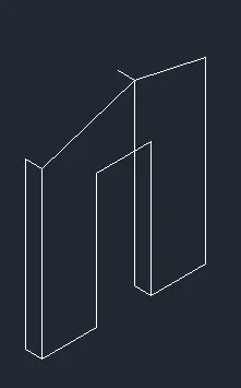
- Next create a inclined line by joining the top end of the mid line
- Next create a width of 0.30
Step4:
- copy the inclined line specify the base point and copy to other side
- next trim the extra line
Result: