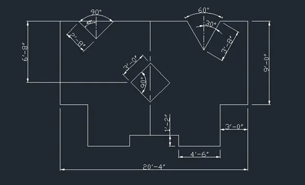
Drafting of various geometries using Chamfer, Fillet tool in AutoCad
1):
Aim: Drafting of given geometries
Introduction: Drafting of given geometries by using Auto Cad
Procedure:
Step1:
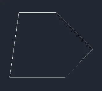
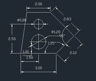
- Take the line by tying l in the command box
- Draw a line of 3 unit in x axis
- Next draw a line with @ 2.12,<45
- Next draw a line with @ 2.83,<135
- Next draw a line with the unit @ -2.0
- Then close.
Step2:
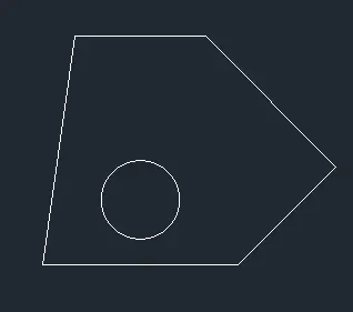
- On the object snap – OSNAP (F3)
- Trak the midpoint enter the unit 1.0
- Take the circle command take the center and diameter draw a circle with dia of 1.20
Step3:
- Trak the midpoint enter the unit 2.50
- Take the circle command take the center and diameter draw a circle with dia of 0.80
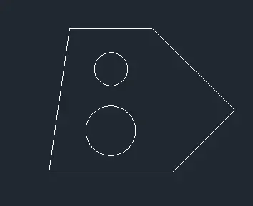
Result:
2):
Aim: Drafting of given geometries
Introduction: Drafting of given geometries by using Auto Cad
Procedure:
Step1:
- Take a line by typing L in the command box
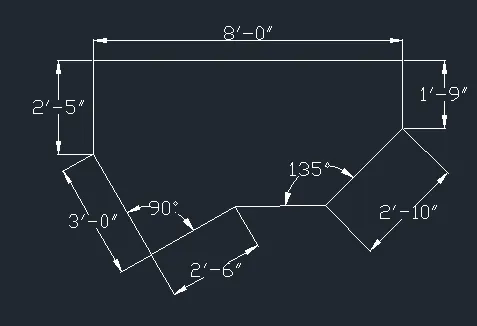
- Draw a line of 8’ in in the x direction
- Next draw a line of unit 1’9” in right sides -y axis
- Next draw a line of unit 2’5” in left sides -y axis
Step2:
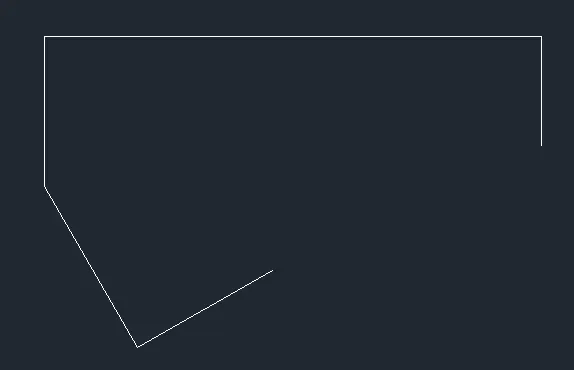
- Next draw a line of unit 3’ with the angle of -60
- Next draw a line of unit 2’6” with the angle of 30
Step3:
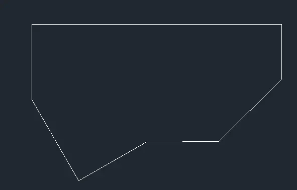
- Next draw a line of unit 2’10” with the angle of -135
- Next join the line.
Result:
3):
Aim: Drafting of given geometries
Introduction: Drafting of given geometries by using Auto Cad
Procedure:
Step1:
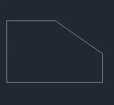
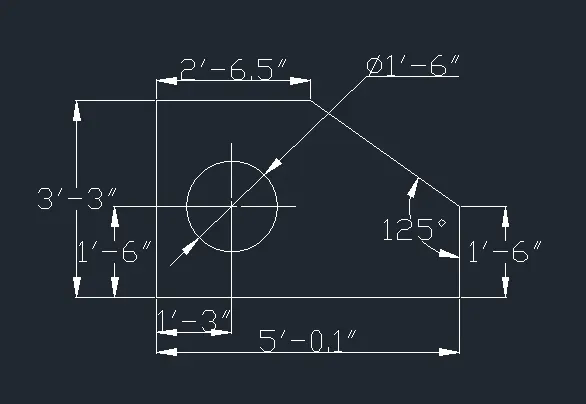
- Take the line command and draw a line of 2’-6.5” in x direction
- Next take the line of 3’-3.0” in y direction
- Next continue line to x direction with the unit 5’-0.1”
- Next continue line in the y direction with unit of 1’-6.0”
- Next close the line
Step2:
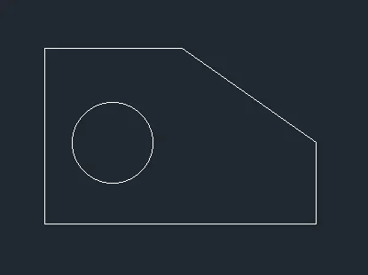
- Take the line command on the object snap tracking
- Mark the distance of 1’3” in the x direction
- Next Mark the distance of 1’6” in the y direction
- Take the circle of center and diameter
- From the center point draw the circle of diameter 1’6”
Result:
4):
Aim: Drafting of given geometries
Introduction: Drafting of given geometries by using Auto Cad
Procedure:
Step1:
- Take the line command by L in the command box
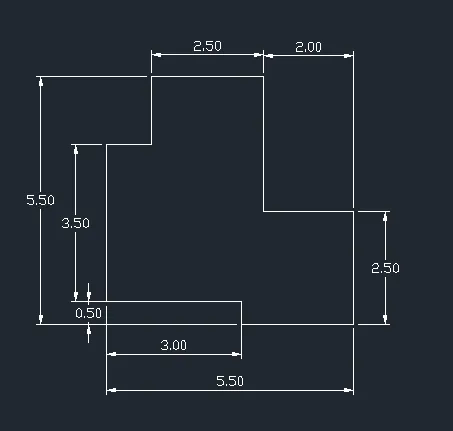
- Draw a line of unit 5.50 in x direction
- On the object snap tracking mark a line at 3.0 with 0.50 in vertical
- Draw a line of unit 3.50 in left direction
- Draw a line of unit 2.50 in right direction
- Next continue draw a line of unit 2.0 in -ve x direction
- Next continue draw a line of unit 3.0 in y direction
- Next continue draw a line of unit 2.50 in -ve x direction
- Next continue draw a line of unit 1.5 in -ve y direction
- Next close the line.
Result:
5):
Aim: Drafting of given geometries
Introduction: Drafting of given geometries by using Auto Cad
Procedure:
Step1:
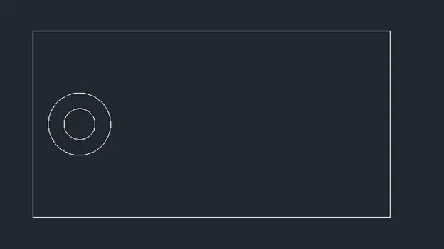
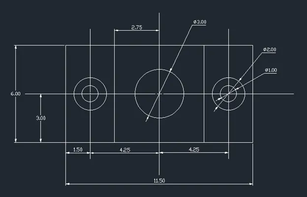
- Take a command rec and draw a rectangle of unit (11.50,6.0).

Step2:
- Type L in the command box and take the line
- Mark the distance of 1.50 in x direction by using object snap tracking
- Mark the distance of 3.0 in y direction by using object snap tracking
- Take the circle command and take the center and diameter
- Make the circle of 2 dia and other circle of dia
Step3:
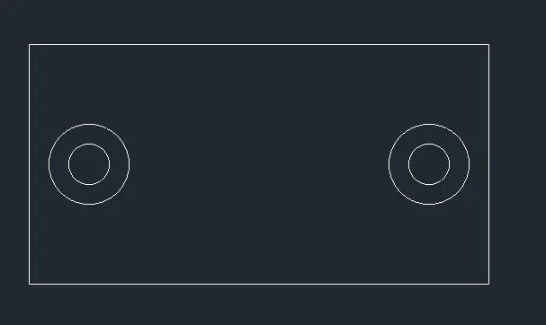
- Draw the another circle at right side of x direction
- Type L in the command box and take the line
- Mark the distance of 1.50 in x direction by using object snap tracking
- Mark the distance of 3.0 in y direction by using object snap tracking
- Take the copy command and copy the circle at center
Step4:
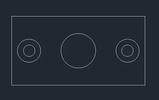
- Type L in the command box and take the line
- Mark the line from center to center of the both circle
- Next take the circle with center and diameter
- Track the mid point and make the circle of 3 diameter
Step4:
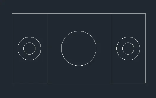
- Type L in the command box and take the line
- Next from the center of the circle mark the distance of 2.75
- Draw a line at both side of the circle.
Result:
6):
Aim: Drafting of given geometries
Introduction: Drafting of given geometries by using Auto Cad
Procedure:
Step1:
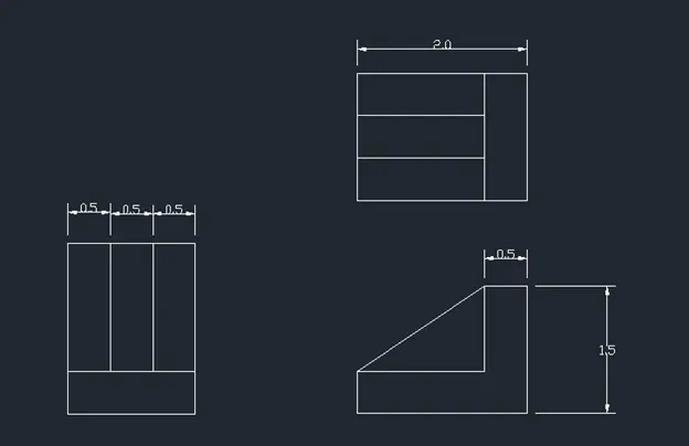
- Take the command rec and make a rectangle of (2.0,1.50)
- Take the offset command and make the offset of 0.50 of vertical line from left side
- Continue to offset command and the offset of 0.5 unit of x axis 2 times.
Step2:
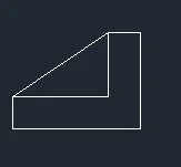
- Take line by typing L in the command box
- Draw a line of 0.50 in x direction
- Continue to line command draw line of unit 1.50 in -y direction
- Continue to line command draw line of unit 2.0 in -x direction
- Continue to line command draw line of unit 5.0 in y direction
- Continue to line command draw line of unit 1.50 in -x direction
Step3:
- Type CO in the command box and take the copy command
- Next copy the above fig
- Next type RO in the command box and take the rotated command
- Next rotated the selected object
Result:
7):
Aim: Drafting of given geometries
Introduction: Drafting of given geometries by using Auto Cad
Procedure:
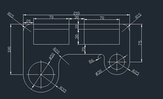
Step1:
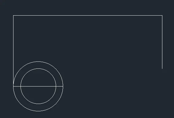
- Take line by typing L in the command box
- Draw a line of unit 210 in the x direction
- Next draw the line of unit 100 in -y direction at left side
- Next draw the line of unit 75 in -y direction at right side
- Draw the another line of 70 unit with the end point of 100 unit line
- Now take command circle and take the circle with the center and radius
- From the mid of the 70 unit line draw the circle the radius of 35
- Take the another circle the center and diameter from the same center point draw a circle with 50 dia
Step2:
- Take line by typing L in the command box
- Draw the line of 50 unit from the end point of 75 unit line
- Now take command circle and take the circle with the center and radius
- From the mid of the 50 unit line draw the circle the radius of 25
- Take the another circle the center and diameter from the same center point draw a circle with 30 dia
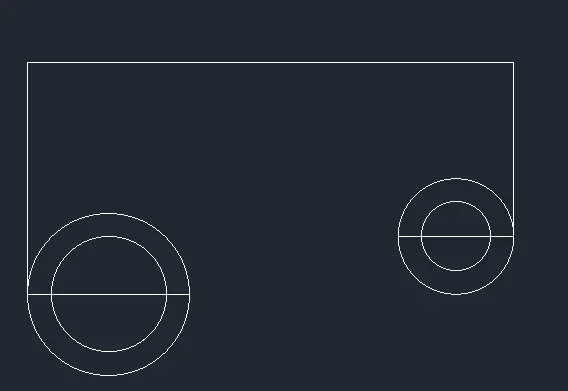
Step:3
- Take line by typing L in the command box
- Now from the end point of 70 unit line draw the vertical line of 40 unit
- Next from the end point of 50 unit line draw the vertical line of 15 unit
- Now join a line from the two end point
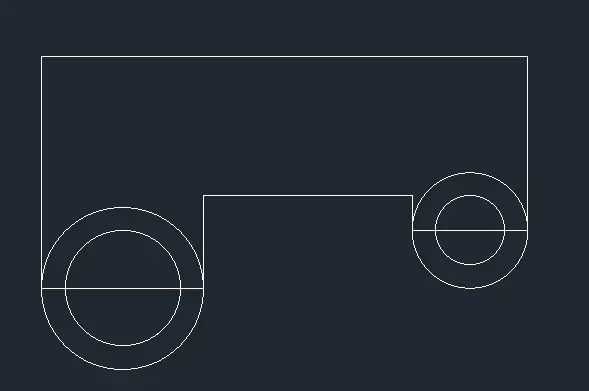
Step4:
- Take the fillet command by typing F in the command box
- Take the fillet of R15 at the conner of 210 line
- Take the fillet of R20 at the conner of 40 line
- Take the fillet of R6 at the conner of 15 line
- Next trim the extra and unwanted lines
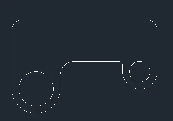
Step5:
- Take line by typing L in the command box
- Mark the distance of 20 unit from the left side of 210 unit line
- Next mark the distance of 10 unit from the top 210 unit line
- Now take the command REC and draw a rectangle of (70,30)
- Repeat same process another rectangle from the right side
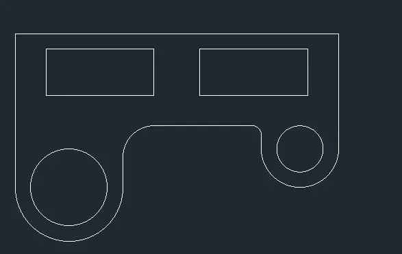
Result:
8):
Aim: Drafting of given geometries
Introduction: Drafting of given geometries by using Auto Cad
Procedure:
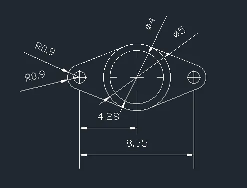
Step1:
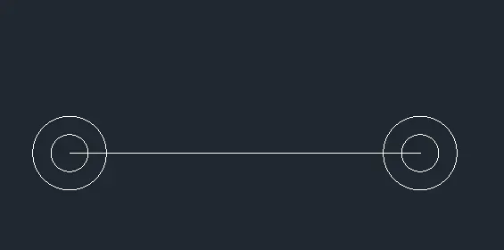
- Take line by typing L in the command
- Draw a horizontal line of 8.55 unit
- Take the circle command and take circle with center and radius
- At the right end of the horizontal line draw a circle with end point as center and 0.90 radius
- Next take the circle with center and diameter
- At the right end of the horizontal line draw a circle with end point as center and 0.90 diameter

Step2:
- Next take the circle command and take circle with center and radius
- At the left end of the horizontal line draw a circle with end point as center and 0.90 radius
- Next take the circle with center and diameter
- At the left end of the horizontal line draw a circle with end point as center and 0.90 diameter
Step3:
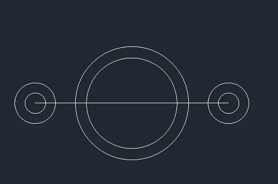
- Take the circle command and take circle with center and diameter
- Now at mid of the line draw a circle with dia of 4.0
- Next from the same center draw another circle with dia of 5.0
Step4:
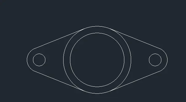
- Take line by typing L in the commad
- now from the object snap take the tangent
- next draw the tangent lines
- next trim the extra lines
Result:
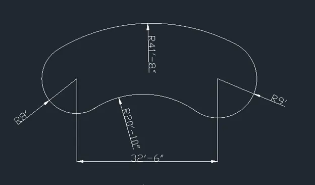
9):
Aim: Drafting of given geometries
Introduction: Drafting of given geometries by using Auto Cad
Procedure:
Step1:
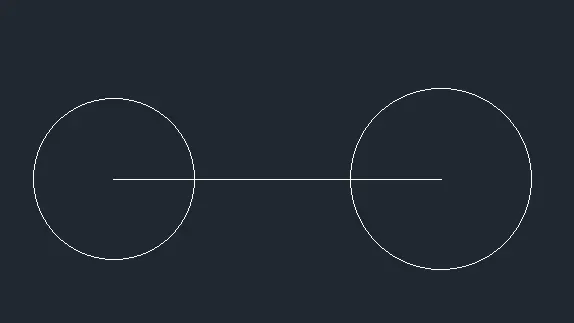
- Take a line by typing L in the command box
- Draw a horizontal line of 32’6”
- Take circle with center and radius
- From the left end point of the line draw a circle of radius 8’

Step2:
- Take circle with center and radius
- From the right end point of the line draw a circle of radius 9’
Step3:
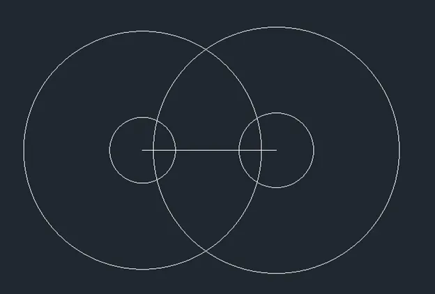
- Now take the offset command by typing O in the command box
- Next take the offset of the two circles with the distance of 20’10”
- The two circle are intersect at bottom
Step4:
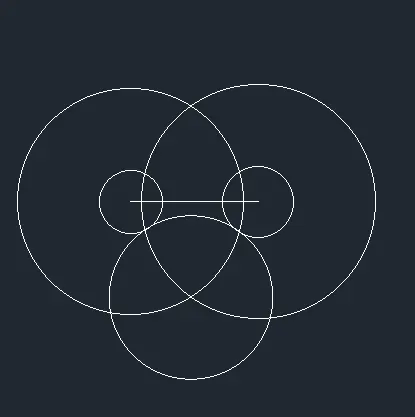
- Take circle with center and radius
- Draw a circle at the intersection of both circle at bottom
- Take the intersection point as the center and radius is 20’10”
- the circle makes a tangent with above two circle
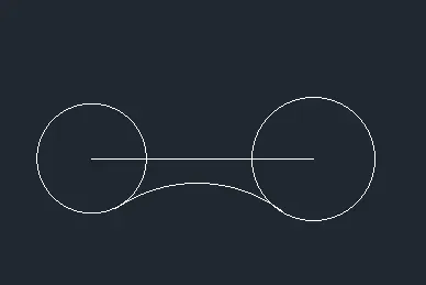
Step5:
- The circle creates the tangent with the above two circles
- Trim the extra lines
Step6:
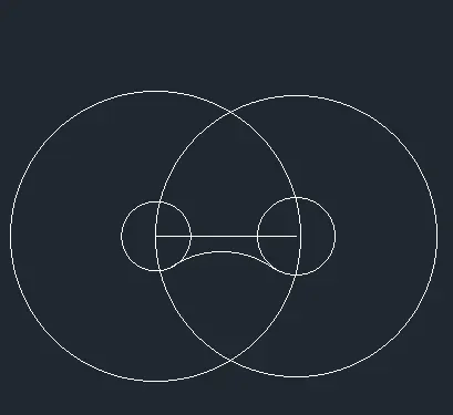
- Now to draw the upper curve
- Take the circle command
- Take the circle with center and radius
- Take the center point as the center of the 9’ circle 32’8” (41’8”-9’)
- Take the center point as the center of the 8’ circle 33’8” (41’8”-8’)
Step7:
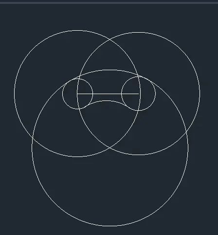
- Take circle with center and radius
- Draw a circle at the intersection of both circle at bottom
- Take the intersection point as the center and radius is 41’8”
- Then it forms the tangent curve with the above two circles
Step8:
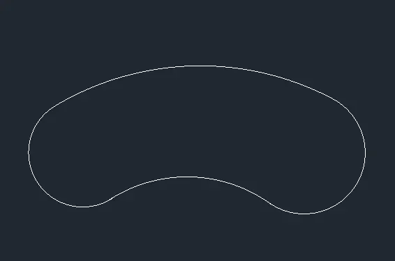
- Now it forms a tangent curve the above of the two circles
- Next trim the extra lines
Result:
10):
Aim: Drafting of given geometries
Introduction: Drafting of given geometries by using Auto Cad
Procedure:
Step1:
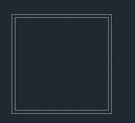
- Take a rectangle by typing REC in the command box
- Draw a rectangle of 5 unit width and 5 unit height
- Now take the offset command by typing O in command box
- Take the offset unit of 0.2
Step2:
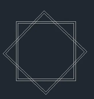
- Next select the object and take the “CO” copy command
- Now rotate the object with help of “RO” rotate command
- Now move the object with help of “M” move command
- now place the object inside the rectangle
Result:
11):
Aim: Drafting of given geometries
Introduction: Drafting of given geometries by using Auto Cad
Procedure:
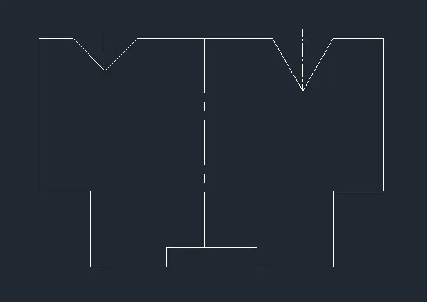
Step1:
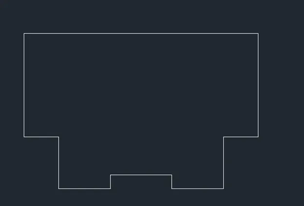
- Take a line by typing L in the command box
- Draw a line unit of 20’4” in x direction
- Continue to line draw a line in -y direction of unit 9’
- Continue to line draw a line in x direction of unit 3’
- Continue to line draw a line in -y direction of unit 4.6’
- Continue to line draw a line in x direction of unit 9’
- Continue to line draw a line in y direction of unit 1’2”
- Continue to line draw a line in x direction of unit 5’4”’
- Continue to line draw a line in -y direction of unit 12”’
- Continue to line draw a line in x direction of unit 46”’
- Continue to line draw a line in y direction of unit 46”’
- Continue to line draw a line in x direction of unit 3’
- Next close the line
Step2:
- Take a line by typing L in the command box
- Draw a line unit of 3’ in x direction from right side
- Next mark a line of 3’7” with an angle of 130
- Mirror the line or object on other side
- Draw a line unit of 2’ in x direction from left side
- Next mark a line of 2’8” with an angle of 45
- Mirror the line or object on other side
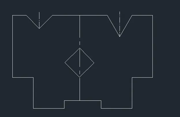
Step3:
- Take the command REC for rectangle
- Draw a rectangle of (3’,3’)
- Next take the rotated
- command by RO in command box
- Rotated the object at 45
Result: