Creation of geometries by Coordinate system methods using AutoCad
Aim: To create the geometries by using all the coordinates system methods. By using the Line tool to create the geometries.
Introduction: To create the geometries by using the Imperial Template and the Decimal Units to draft the features. By using the software AutoCAD.
Procedure:
Step:1
- Drawing line in AutoCAD
Ribbon: Home > Draw > Line
Toolbar: Draw > Line
Menu Bar: Draw > Line
Tool Palettes: Draw > Line
Command: Draw > Line
Step:2
coordinates system:
- Absolute coordinate
- Relative coordinate
- Relative rectangular coordinate
- Relative polar coordinate
- Direct distance entry
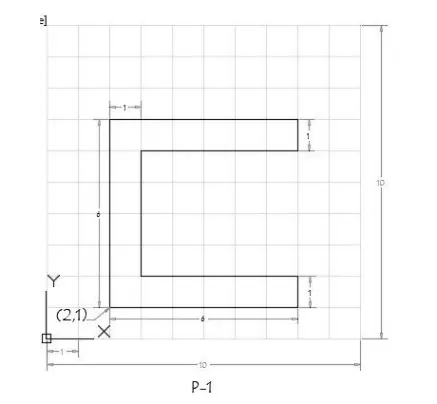
Absolute coordinate: In this system the distances is measured with respect to origin are
- Type the command “L” for the line and give the coordinate for point 1 (2,1)
- Type the next coordinate of point 2 (2,7) in the command box
- Type the next coordinate of point 3 (8,7) in the command box
- Type the next coordinate of point 4 (8,6) in the command box
- Type the next coordinate of point 5 (3,6) in the command box
- Type the next coordinate of point 6 (3,2) in the command box
- Type the next coordinate of point 7 (8,2) in the command box
- Type the next coordinate of point 8 (8,1) in the command box
- Click close on the command box
Result:
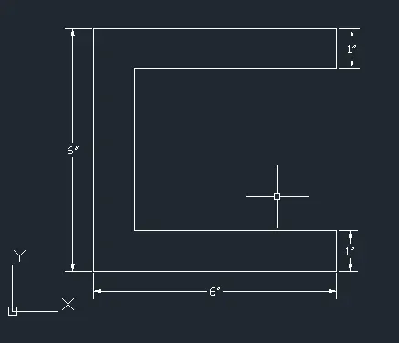
Drawing the figure using Absolute coordinate system
2).a) Relative rectangular coordinate: In this system the coordinates are measured from the previous point
- Type the command “L” for the line and give the coordinate for point 1 (2,1)
- Type the next coordinate of point 2 @ (0,6) in the command box
- Type the next coordinate of point 3 @ (6,0) in the command box
- Type the next coordinate of point 4 @ (0,-1) in the command box
- Type the next coordinate of point 5 @ (-5,0) in the command box
- Type the next coordinate of point 6 @ (0,-4) in the command box
- Type the next coordinate of point 7 @ (5,0) in the command box
- Type the next coordinate of point 8 @ (0,-1) in the command box
- Click close on the command box
Result:
Drawing the figure using Relative rectangular coordinate system
2.b). Relative polar coordinate: in this poplar coordinated system the coordinate and the angle with respect x axis is given
- Type the command “L” for the line and give the coordinate for point 1 (2,1)
- Type the next coordinate of point 2 @ 6<90 in the command box
- Type the next coordinate of point 3 @ 6<0 in the command box
- Type the next coordinate of point 4 @ 1<270 in the command box
- Type the next coordinate of point 5 @ 5<180 in the command box
- Type the next coordinate of point 6 @ 4<270 in the command box
- Type the next coordinate of point 7 @ 5<0 in the command box
- Type the next coordinate of point 8 @ 1<270 in the command box
- Click close on the command box
Result:
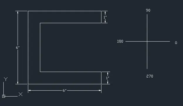
Drawing the figure using Relative polar coordinate system
Direct distance entry: In this method specify the first point position the cursor and then enter the distances.
- Type the command “L” for the line.
- Type the length 6 in command box to +ve y-axis
- Type the length 6 in command box to +ve x-axis
- Type the length 1 in command box to -ve y-axis
- Type the length 5 in command box to -ve x-axis
- Type the length 4 in command box to -ve y-axis
- Type the length 5 in command box to +ve x-axis
- Type the length 1 in command box to -ve y-axis
- Click close on the command box
Result:
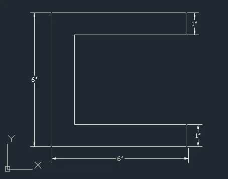
Drawing the figure using Direct distance entry system
2):
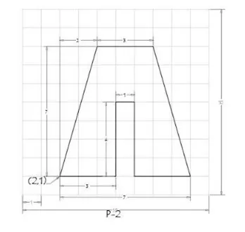
Absolute coordinate: In this system the distances is measured with respect to origin are
- Type the command “L” for the line and give the coordinate for point 1 (2,1)
- Type the next coordinate of point 2 (4,8) in the command box
- Type the next coordinate of point 3 (7,8) in the command box
- Type the next coordinate of point 4 (9,1) in the command box
- Type the next coordinate of point 5 (6,1) in the command box
- Type the next coordinate of point 6 (6,5) in the command box
- Type the next coordinate of point 7 (5,5) in the command box
- Type the next coordinate of point 8 (5,1) in the command box
- Click close on the command box
Result:
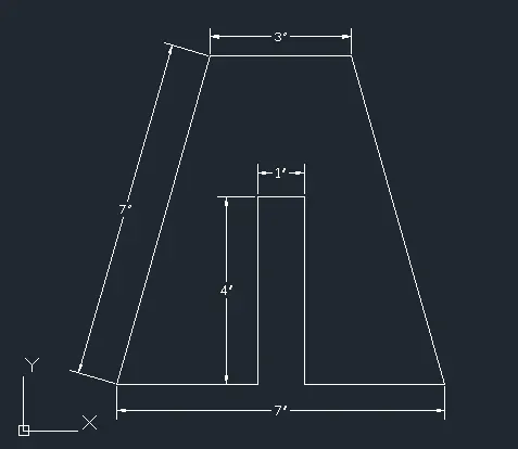
Drawing the figure using Absolute coordinate system
2) a). Relative rectangular coordinate: In this system the coordinates are measured from the previous point
- Type the command “L” for the line and give the coordinate for point 1 (2,1)
- Type the next coordinate of point 2 @ (2,7) in the command box
- Type the next coordinate of point 3 @ (3,0) in the command box
- Type the next coordinate of point 4 @ (2-7) in the command box
- Type the next coordinate of point 5 @ (-3,0) in the command box
- Type the next coordinate of point 6 @ (0,4) in the command box
- Type the next coordinate of point 7 @ (-1,0) in the command box
- Type the next coordinate of point 8 @ (0,-4) in the command box
- Click close on the command box
Result:
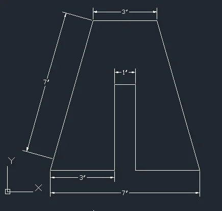
Drawing the figure using Relative rectangular coordinate system
2.b). Relative polar coordinate: in this poplar coordinated system the coordinate and the angle with respect x axis is given
- Type the command “L” for the line and give the coordinate for point 1 (2,1)
- Type the next coordinate of point 2 @ 3<0 in the command box
- Type the next coordinate of point 3 @ 4<90 in the command box
- Type the next coordinate of point 4 @ 1<0 in the command box
- Type the next coordinate of point 5 @ 4<270 in the command box
- Type the next coordinate of point 6 @ 3<0 in the command box
- Type the next coordinate of point 7 @ 7<0 in the command box
- Type the next coordinate of point 8 @ 2<0 in the command box
- Type the next coordinate of point 9 @ 3<0 in the command box
- Click close on the command box
- Join the line 3<0 top & and bottom
- Delete the extra line 7<0 & 2<0
Result:
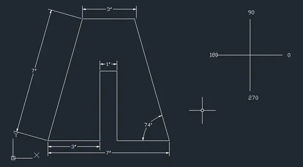
Drawing the figure using Relative polar coordinate system
Direct distance entry: In this method specify the first point position the cursor and then enter the distances.
- Type the command “L” for the line and give the coordinate for point 1 (2,1)
- Type the length 3 in command box to +ve x-axis
- Type the length 4 in command box to +ve y-axis
- Type the length 1 in command box to +ve x-axis
- Type the length 4 in command box to -ve y-axis
- Type the length 3 in command box to +ve x-axis
- Type the length 7 in command box to +ve y-axis
- Type the length 2 in command box to -ve x-axis
- Type the length 3 in command box to -ve x-axis
- Join the line from top to bottom
- Delete the extra line
- Click close on the command box
Result:
Drawing the figure using Direct distance entry system
3):
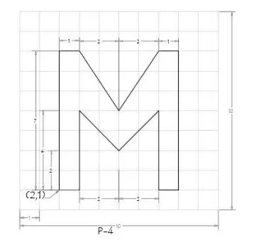
Relative rectangular coordinate: In this system the coordinates are measured from the previous point
- Type the command “L” for the line and give the coordinate for point 1 (2,1)
- Type the next coordinate of point 2 @ (0,7) in the command box
- Type the next coordinate of point 3 @ (1,0) in the command box
- Type the next coordinate of point 4 @ (-2,-3) in the command box
- Type the next coordinate of point 5 @ (-2,3) in the command box
- Type the next coordinate of point 6 @ (1,0) in the command box
- Type the next coordinate of point 7 @ (0,-7) in the command box
- Type the next coordinate of point 8 @ (-1,0) in the command box
- Type the next coordinate of point 9 @ (0,4) in the command box
- Type the next coordinate of point 10@ (-2,-2) in the command box
- Type the next coordinate of point 11@ (-2,2) in the command box
- Type the next coordinate of point 12 @ (0,-4) in the command box
- Click close on the command box
Result:
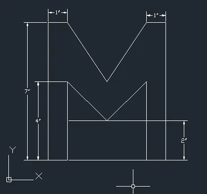
Drawing the figure using Relative rectangular coordinate system
4):
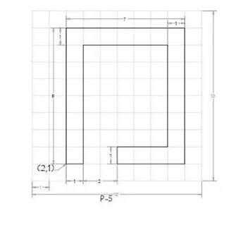
Relative rectangular coordinate: In this system the coordinates are measured from the previous point
- Type the command “L” for the line and give the coordinate for point 1 (2,1)
- Type the next coordinate of point 2 @ (0,8) in the command box
- Type the next coordinate of point 3 @ (-7,0) in the command box
- Type the next coordinate of point 4 @ (0-8) in the command box
- Type the next coordinate of point 5 @ (-4,0) in the command box
- Type the next coordinate of point 6 @ (0,1) in the command box
- Type the next coordinate of point 7 @ (3,0) in the command box
- Type the next coordinate of point 8 @ (0,1) in the command box
- Type the next coordinate of point 9 @ (3,0) in the command box
- Type the next coordinate of point 10@ (0,6) in the command box
- Type the next coordinate of point 11@ (-5,0) in the command box
- Type the next coordinate of point 12 @ (0,-7) in the command box
- Click close on the command box
Result:
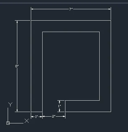
Drawing the figure using Relative rectangular coordinate system
5):
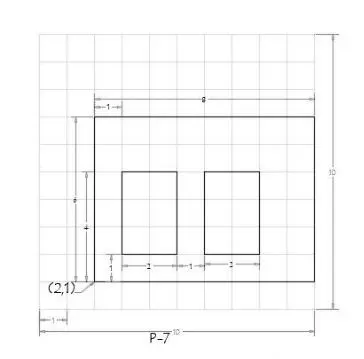
Relative rectangular coordinate: In this system the coordinates are measured from the previous point
- Type the command “L” for the line and give the coordinate for point 1 (2,1)
- Type the next coordinate of point 2 @ (0,6) in the command box
- Type the next coordinate of point 3 @ (8,0) in the command box
- Type the next coordinate of point 4 @ (0-6) in the command box
- Click close on the command box
- Type the command “L” for the line and give the coordinate for point (3,2)
- Type the next coordinate of point 5 @ (0,3) in the command box
- Type the next coordinate of point 6 @ (2,0) in the command box
- Type the next coordinate of point 7 @ (0,-3) in the command box
- Click close on the command box
- Type the command “L” for the line and give the coordinate for point (6,2)
- Type the next coordinate of point 8@ (0,) in the command box
- Type the next coordinate of point 9@ (2,0) in the command box
- Type the next coordinate of point 10 @ (0,-3) in the command box
- Click close on the command box
Result:
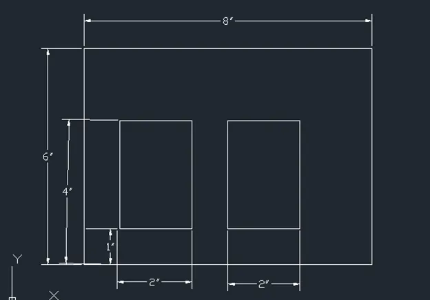
Drawing the figure using Relative rectangular coordinate system
6):
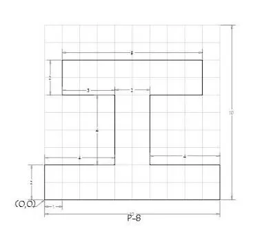
Relative rectangular coordinate: In this system the coordinates are measured from the previous point
- Type the command “L” for the line and give the coordinate for point 1 (0,0)
- Type the next coordinate of point 2 @ (0,2) in the command box
- Type the next coordinate of point 3 @ (4,0) in the command box
- Type the next coordinate of point 4 @ (0,4) in the command box
- Type the next coordinate of point 6 @ (-3,0) in the command box
- Type the next coordinate of point 7 @ (0,2) in the command box
- Type the next coordinate of point 8 @ (8,-0) in the command box
- Type the next coordinate of point 9@ (0,-2) in the command box
- Type the next coordinate of point 10@ (-3,0) in the command box
- Type the next coordinate of point 11 @ (0,-4) in the command box
- Type the next coordinate of point 12 @ (3,0) in the command box
- Type the next coordinate of point 13 @ (0,-2) in the command box
- Click close on the command box
Result:
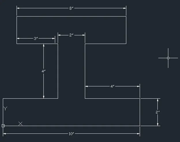
Drawing the figure using Relative rectangular coordinate system
7):
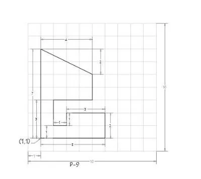
Relative rectangular coordinate: In this system the coordinates are measured from the previous point
- Type the command “L” for the line and give the coordinate for point 1 (1,1)
- Type the next coordinate of point 2 @ (0,7) in the command box
- Type the next coordinate of point 3 @ (4,-2) in the command box
- Type the next coordinate of point 4 @ (0,-2) in the command box
- Type the next coordinate of point 6 @ (-3,0) in the command box
- Type the next coordinate of point 7 @ (0,-2) in the command box
- Type the next coordinate of point 8 @ (1,0) in the command box
- Type the next coordinate of point 9@ (0,1) in the command box
- Type the next coordinate of point 10@ (3,0) in the command box
- Type the next coordinate of point 11 @ (0,-2) in the command box
- Click close on the command box
Result:
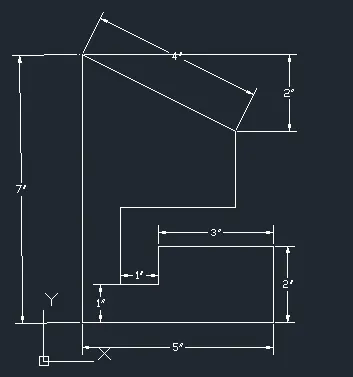
Drawing the figure using Relative rectangular coordinate system
8):
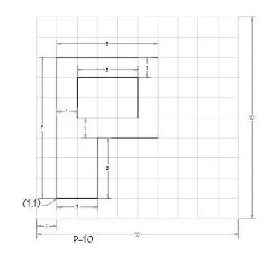
Relative rectangular coordinate: In this system the coordinates are measured from the previous point
- Type the command “L” for the line and give the coordinate for point 1 (1,1)
- Type the next coordinate of point 2 @ (0,7) in the command box
- Type the next coordinate of point 3 @ (5,0) in the command box
- Type the next coordinate of point 4 @ (0,-4) in the command box
- Type the next coordinate of point 6 @ (-3,0) in the command box
- Type the next coordinate of point 7 @ (0,-3) in the command box
- Click close on the command box
- Type the command “L” for the line and give the coordinate for point 8 (2,5)
- Type the next coordinate of point 9@ (0,2) in the command box
- Type the next coordinate of point 10@ (5,0) in the command box
- Type the next coordinate of point 11 @ (0,-2) in the command box
- Click close on the command box
Result:
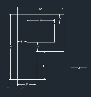
Drawing the figure using Relative rectangular coordinate system
9):
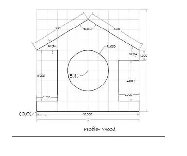
Relative rectangular coordinate: In this system the coordinates are measured from the previous point
- Type the command “L” for the line and give the coordinate for point 1 (0,0)
- Type the next coordinate of point 2 @ (0,1) in the command box
- Type the next coordinate of point 3 @ (2,0) in the command box
- Type the next coordinate of point 4 @ (0,5) in the command box
- Type the next coordinate of point 6 @ (-2,0) in the command box
- Type the next coordinate of point 7 @ (5,3) in the command box
- Type the next coordinate of point 9@ (5,-3) in the command box
- Type the next coordinate of point 10@ (0,-1) in the command box
- Type the next coordinate of point 11 @ (-2,0) in the command box
- Type the next coordinate of point 12 @ (0,-4) in the command box
- Type the next coordinate of point 13 @ (-1,0) in the command box
- Type the next coordinate of point 14 @ (0,-1) in the command box
- Click close on the command box
- Type the in the command box and take the centre and radius
- Type the coordinate of the centre (5,4) in the command box
- Type the diameter of the circle 2 in the command box.
Result:
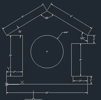
Profile-wood
Drawing the figure using Relative rectangular coordinate system
10):
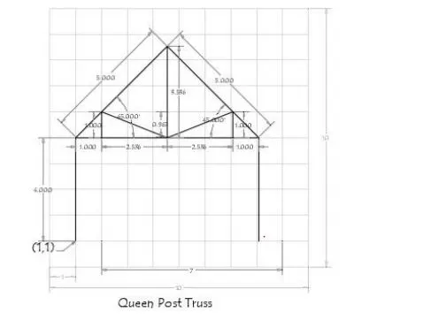
Direct distance entry: In this method specify the first point position the cursor and then enter the distances.
- Type the command “L” for the line and give the coordinate for point 1 (1,1)
- Type the length 4 in command box to +ve y-axis
- Type the length 7 in command box to +ve x-axis
- Type the length -4 in command box to -ve y-axis
- Take the point (1,5) and mark the line with length 5 and angle 45
- Take the end point join the midpoint of the below line
- Take the mid point of the above line and join the edge point of the below line
- From the midpoint of line (4,7) take the distance of 2.5 and join the line at point (2,5)
- From the midpoint of line (4,7) take the distance of 2.5 and join the line at point (7,5)
- Click close on the command box
Result:
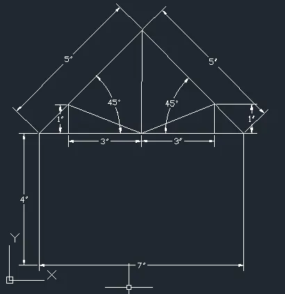
Queen post truss
Drawing the figure using Direct distance entry system
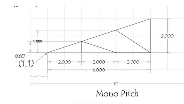
Direct distance entry: In this method specify the first point position the cursor and then enter the distances.
- Type the command “L” for the line and give the coordinate for point 1 (1,1)
- Type the length 2 at a point (7,2) in command box to +ve y-axis
- Join the two end points
- From the point (1,1) take the distance 2 and make a vertical line and join the above line
- From the point (2,2) take the distance 2 and make a vertical line and join the above line
- From the point (4,2) take the distance 2 and make a vertical line and join the above line
- Now join the inclined line last end point to vertical line top point
- Now join the inclined line from the point 4 to vertical line top point
Result:
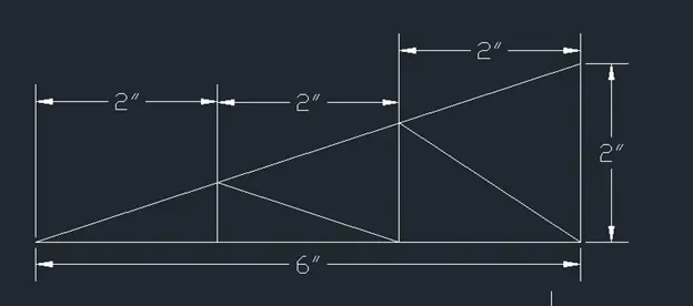
Mono pitch
Drawing the figure using Direct distance entry system