Project 2_Creating a 3D rendered model for a Residential Building in AutoCad
1. Aim: To create a 3D model of the residential building with a rendered view
Introduction: The main objective of this project is to understand about to create a plan in 2D and then convert it into 3D using AutoCAD 3D software
- AutoCAD is primarily used for generating 2D models
- Now-a-days 3D models are widely used by Architects and Designers to showcase their designs to the clients
- Automatically all the companies want to see their future buildings in 3D architectural renderings
Commands used:
- Line
- Rectangle
- UCS
- Offset
- Arc
- Dimlinear
- Dimaligned
- Region
- Extrude
- Subtract
- Box
- Units
- Dimstyle
- 3Dorbit
- 3Dface
- Move
- Copy
- Array
- Solidedit
- Union
- Boundary
- 3Dmirror
- 3Drotate
- Erase
- Chamfer
- Plan
Procedure:
Step1:
- Open AutoCAD software
- Start new drawing
- Type Units and set to it Engineering
- Type LIMMAX and set the limits to 100',100'
- Type Z and enter then select All
- Type XLINE and click enter
- Choose Horizontal at once and then Vertical
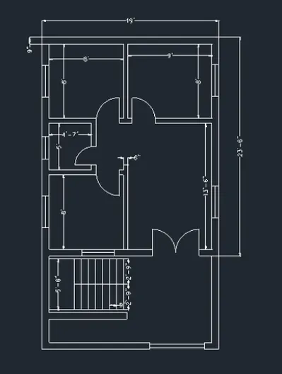
- Make offset 9" of outer line on both sides
- Draw the lines of internal walls with thickness of 4.5"
- Draw the doors and windows using line, arc command
- Plot the dimensions using dimlinear and dimaligned command
- The final image of plan is drafted as shown in figure
Step2:
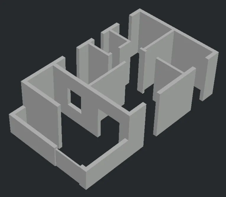
- Turn 2D view to isometric view of the plan
- Type BO and enter then choose region from it
- Select the objects and make them regions
- Extrude the objects of selected regions with height 10'
- Use subtract command for the door openings and windows as shown in figure
Step3:
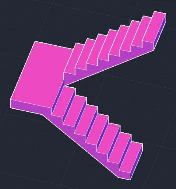
- Draw the stairs with line command in 3D
- The riser of 7.5" and tread of 9"
- The final image of 3D stairs are as follows
Step4:
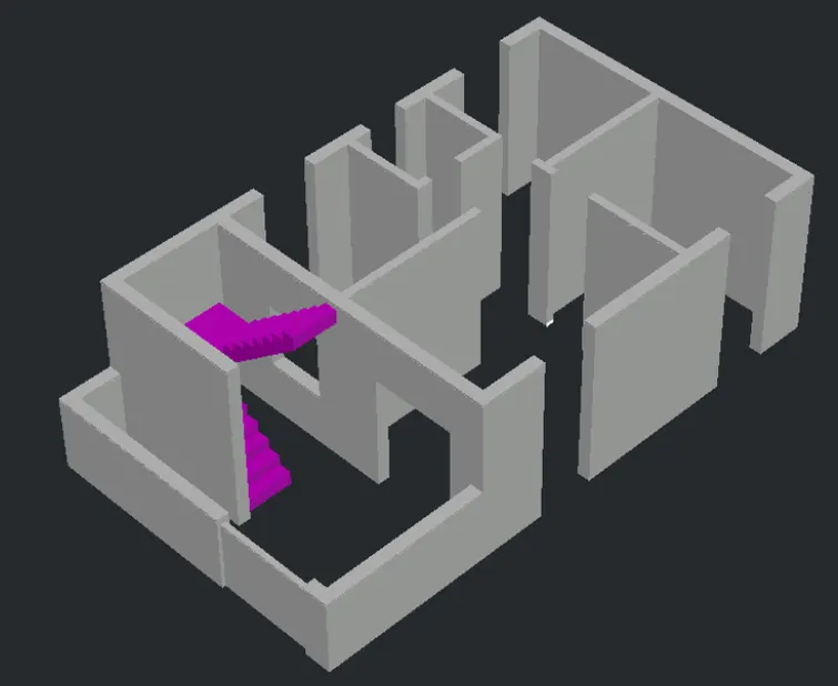
- Insert staircase in the isometric view of plan
- By using the move command and place it
- The image after placing staircase are as follows
Step5:
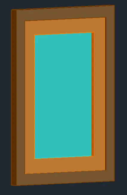
- Draw the windows as per Industrial Standards 3'*4'
- The sizes of windows are same for everyone
Step6:
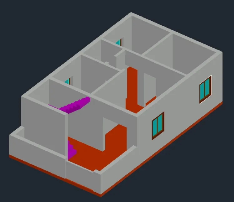
- Place the windows in isometric view by using move command
- The flooring is done with rec command, extrude and then placed
- The image is as follows after placing windows and flooring
Step7:
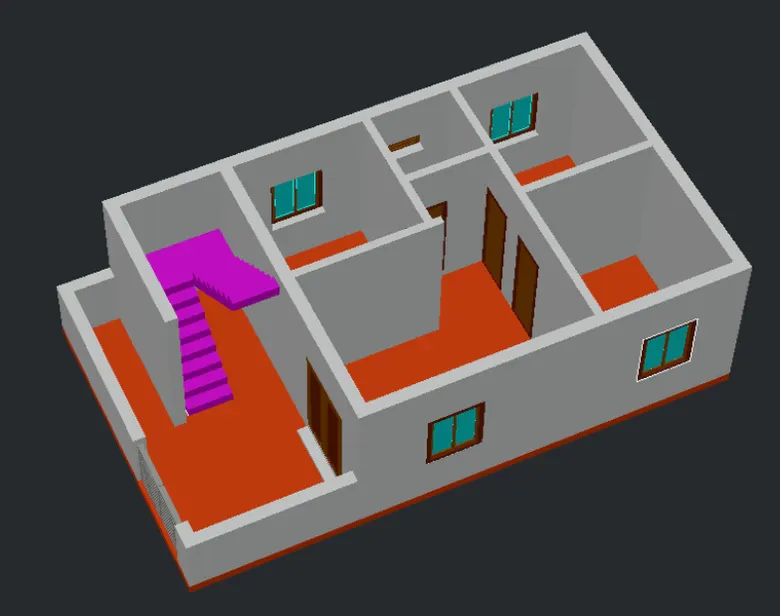
- Draw the doors as per Industry Standards 4'5"*7' for main door and 2.9'*7' for inside doors
- The dimensions of all inside doors are same
- By using move command place the doors in it
- The image are as follows
Step8:
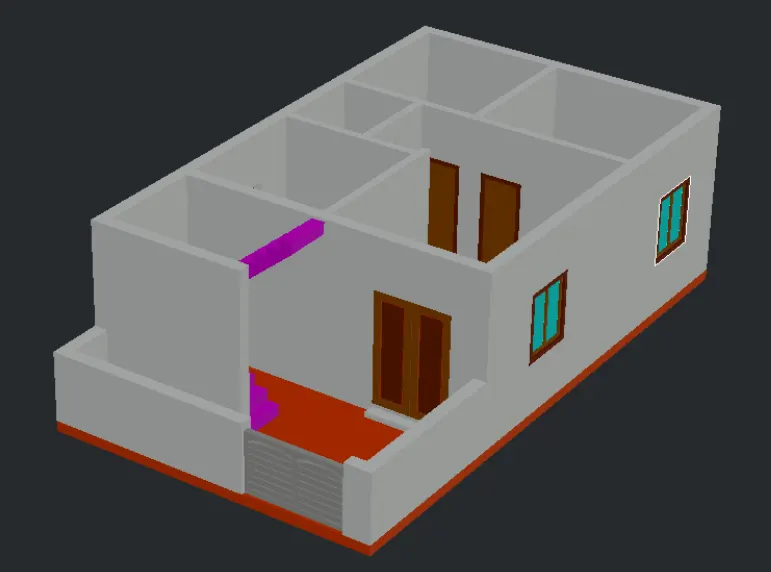
- Turn the plan to another view using 3D orbit
- The image is as follows
Step9:
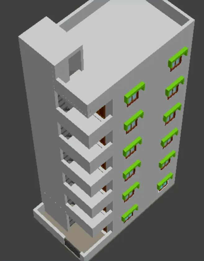
- By using copy command and select the image
- Use array command to make it into 5 floors
- Draw parapet wall with height 4'
- Draw sunshades
- The final image are as follows
Step10:
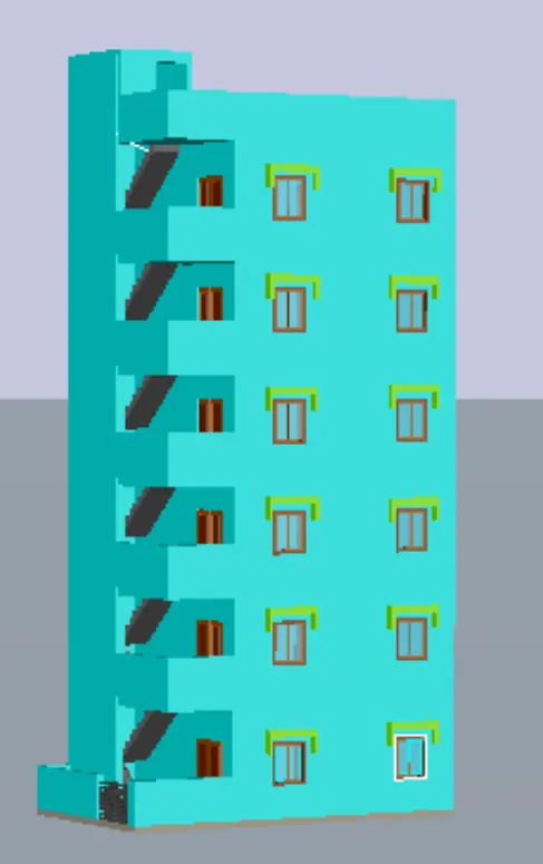
- Using Material browser select the materials and apply it
- The final image are as follows
Step11:
- The rendered image after loading are as follows
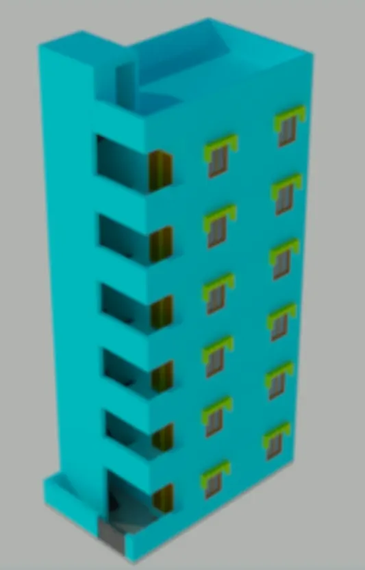
Result: The 3D model of the residential building with a rendered view is drafted by using AutoCAD 3D software