Project 2_Creating a 3D rendered model for a Residential Building in AutoCad
aim:
Create a 3 dimensional model of the residential building with a rendered view.
area of residential: 40'*30'
storey:G+1+parapett
step 1:
draw the 2d plan using some autocadd tools ,
tools were used :rec
offset
layer
mtext
copy mirror
etc..
procedure :
draw the rec to create the area and wall outer
offset to create the rooms,walls etc
trim the unecessary line to get the perfection of the drawing
layer prop to seperate the elements
text has used to know the names
those commands are used to create the residential building
result: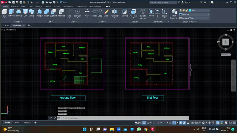
step -2
create the 3d doors and windows using 3d modelling interface
tools were used:
offset
extrude
press pull
region
boundary
material properties
procedure:
doors size
D1-4',7'
offset to cretae the panel which is 3"and inner panle is 4"
create boundary over the inner rec then opt extrude to create the panel of the door
and inside 3df is create over inner to appy the glass materia to show the door
door is created using 3d modelling
3d model door has been created .
window size
w1-6',4'
w2-4',4,
W3- 3',4'
what we have did in door procedure here we going to make the door procedure for window .
result: 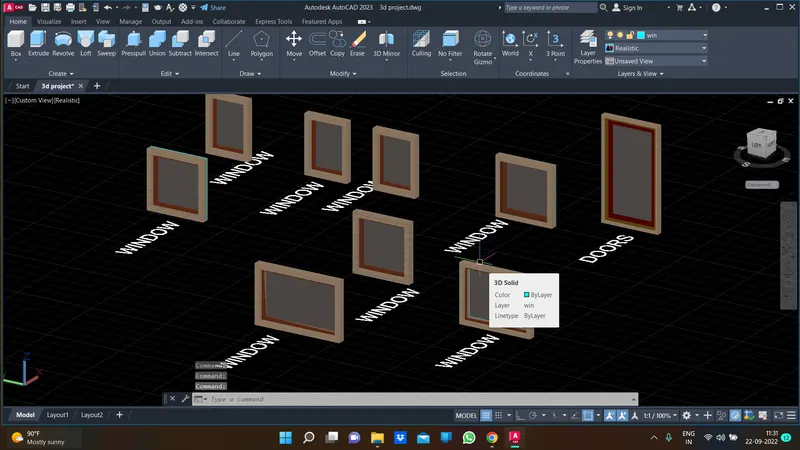
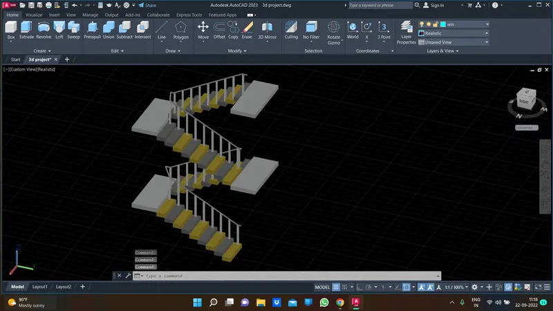
step-3 create the stairs (3d stairs )
tools were used :
rec
offset
extrude
press pull
copy
array
sweep
line
material browser
procedure
stairs
tread-1'
riser-6"
we need to find the no of steps
steps=height of building/riser
=10'/.5'
20 steps for the stair
no of tread =riser -1
20-1=19 tread
create the 2d stair drawing and open the 3d model interface
and press pull it the stair and copy and fix the landing and steps wherever we want
we just did that on our assumption
the shape of the stair is zig zag
at last we need to give some texture for the stair to show the stair perfectly
and need to create the hand rail and bullstrades
make the circle to create the sweep for hand rails and ballustrades
result:
step-4
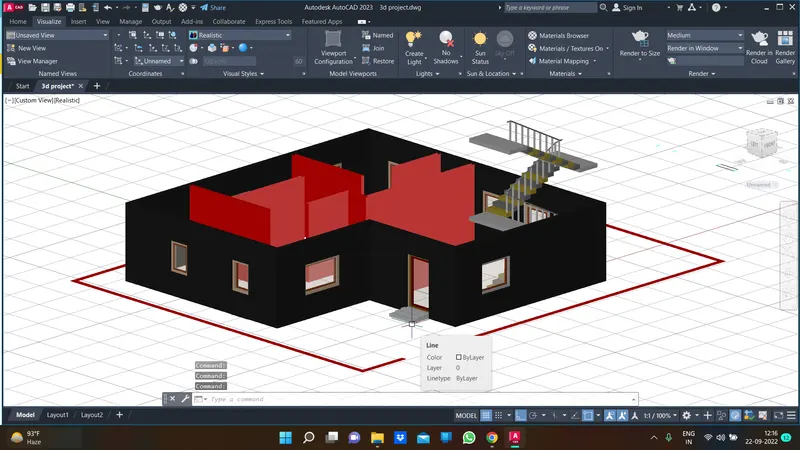
to create the 3d building using 2d plan as a reference
tools were used :extrude
boundary
etc..
procedure:
to extrude the wall i mean outer wall extrude it as 10'
create the extrude excluding window , door area
once finish the extruding the need to create the voids for the window and doors
window sill height would be 3'
alread we have made the doors and windows now we can attach the respected area ..and fabricated stair also fixed at the respected place where we drew the 2d plan
result:
step-5
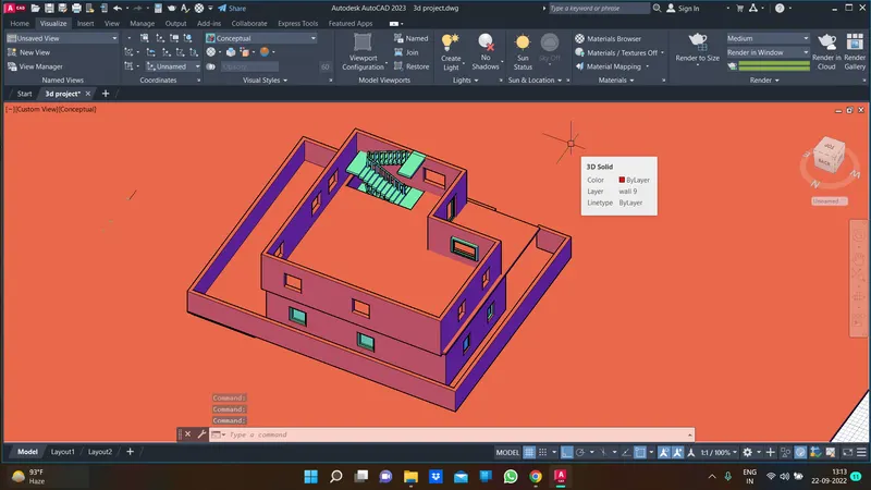
to create the first flloor as per 2d plan
and it is a conceptual diagram
make extrude to finish of all this
floor is made by press pull which thickness is 6"
result:
step 6:
to create the elevation for this residential house using 3d tools
tools were used :
extrude
press pull
sweep
etc ..
procedure:
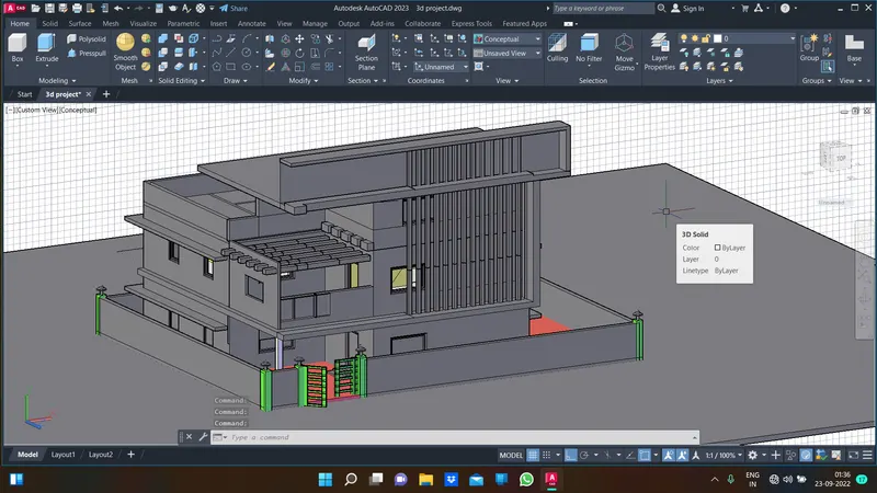
create the elevation for the residential house
create the sunshades which thickness is 6" and length is 2'
first create the rec and extrude it and then fix it over the top of the window
create the front elevation design using sweep , loft , presspull etc has been did for this and create the
compound wall around the residential building
which height is 5'9" and each corner comprised of high width short column and the lamp placed over the top of the high width column and gate is made by using extrude rec , sweep to did that thing.. extrusion is the main thing we just involve them into it to create front elevation aesthetically ..it is conceptual model;;
result:
`
step-7
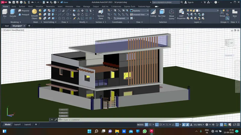
to make the building realistic and aethetically good
tools were used:
material browser
procedure:
open the material browse dialog box then apply the paint
textures and glasses for the building to make beautifull
result:
step 8:
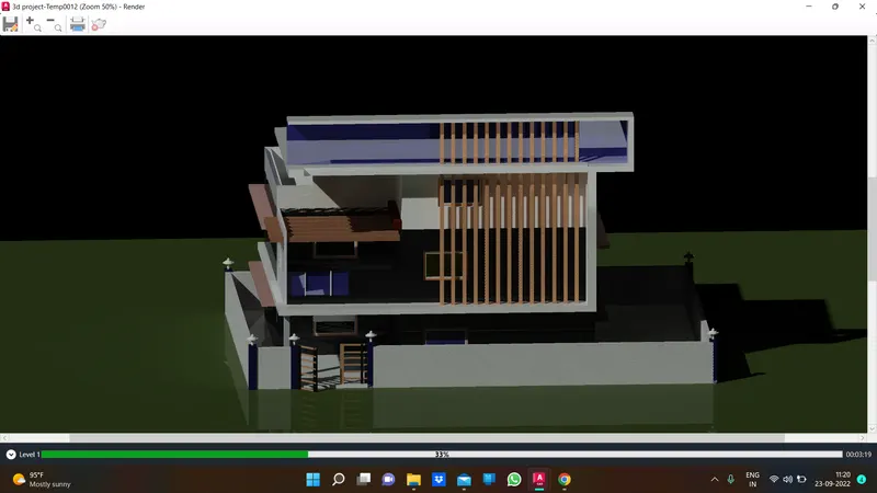
render the resedential building
tools were used
RR render
render opt
procedure :
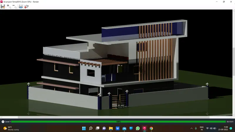
type rr to render the respected building for the realistic view of the predicted building
wait for some minutes to get the render detailed
here the
picture of the rendrerd building of some views
result:rendered
pic 1
pic 2
step 9 :
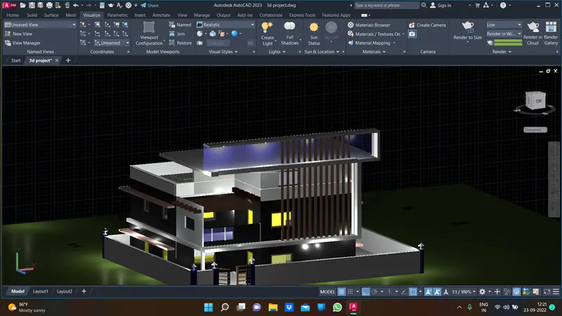
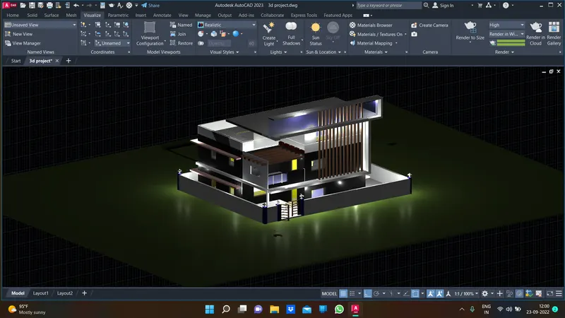
render with some applying light
apply light is for predict the how the was in night time and day time
tools were used
light
point light
web light
path light
etc <<...
procedure
appy the point light in the dark area to make the building glow in the night time
and here the applied point light with building is given below
give some intensity to brighter the light
some edit works are there so we could edit that all things to make light good
result:
pic 1:
pic
pic 3
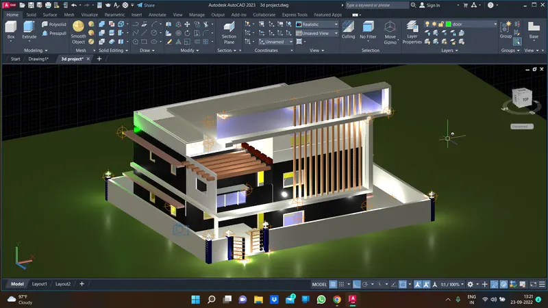
final step
to make the camera angles to show prespective view of the building
tools were used :
camera :
view 1
view 2
view 3
view 4
procedure:first press the cam option to fix the camera whre we want
and edit the camera opt to give name
how much wide we want
which angle we need to set
once finished this type of setting then we just press the camera to see the view of the building
result : camera view 1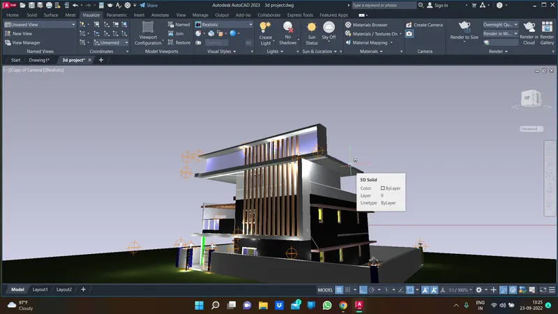
camera view 2
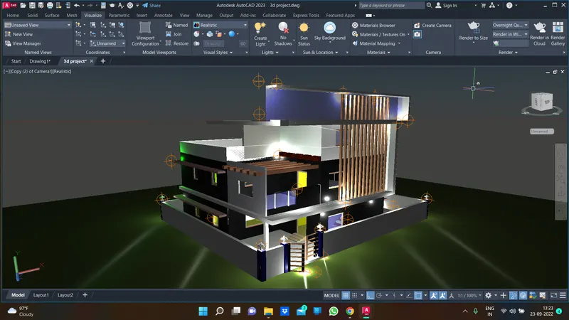
camera view 3
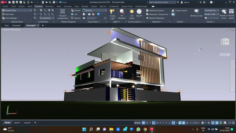
camera view 4 with day condition ::
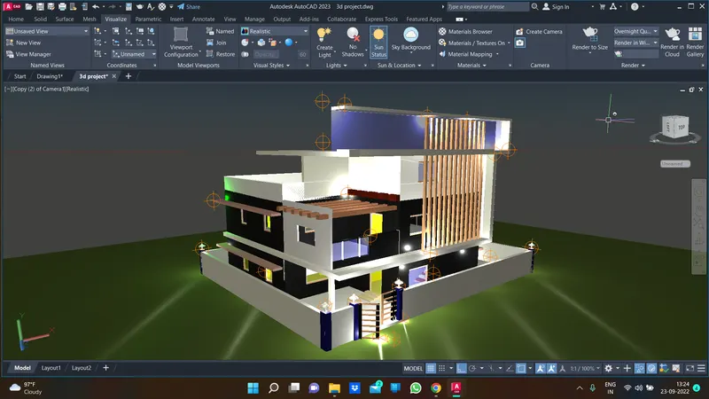
conclusion :
a 3 dimensional model of the residential building with a rendered view. has been created........,.... using autocadd