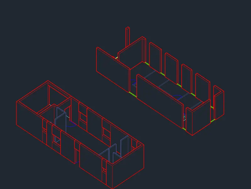
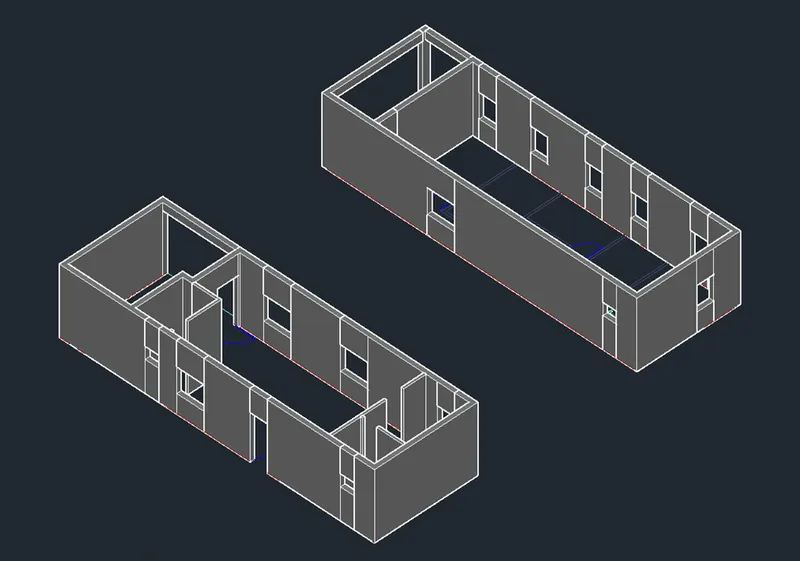
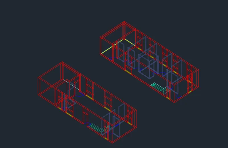
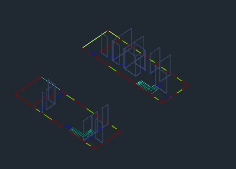
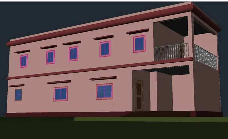
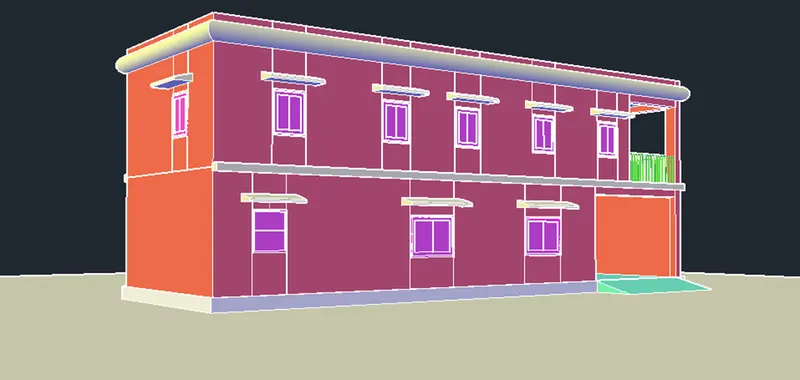
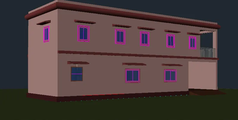
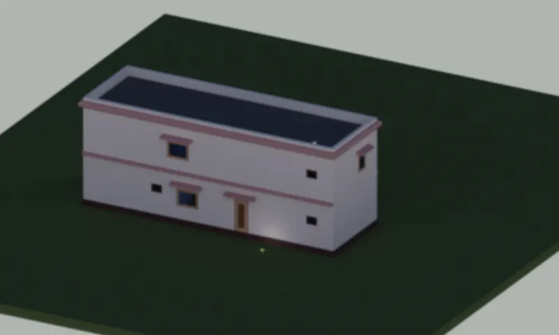
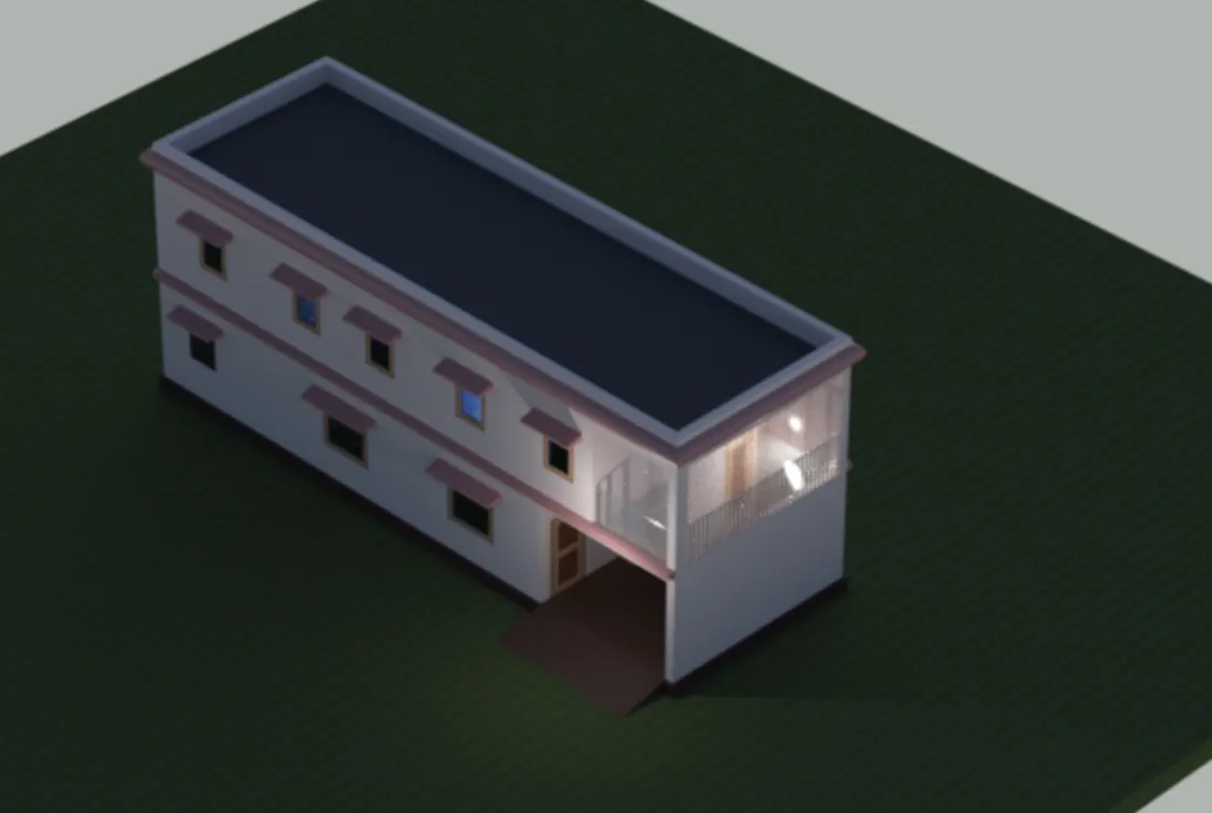
Project 2_Creating a 3D rendered model for a Residential Building in AutoCad
Week 13-Project 2-Module 2
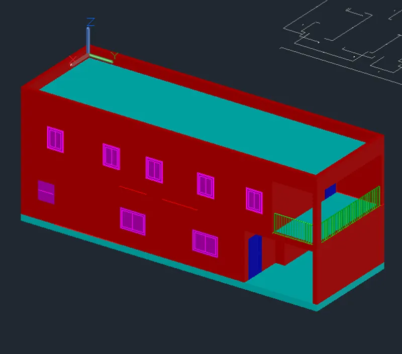
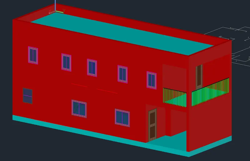
Aim: To create a 3D rendered model for a Residential Building in AutoCad.
Introduction:
- 3D modeling is a more advance form of drawing presentation in architecture, and construction. 3D models are used to visualize, simulate and render graphic designs.
- It gives additional boost to the efficient communication on how the project would be once constructed.
- For this Project, our 3D rendered model will be based on what was created on Project 1 under after the week 8 session with some assumption such as additional aesthetics features of the project perspective.
Procedure:
A. Setting the Drawing Parameters;
- Set up the measurement units as metric measured in millimeters.
- To set up that, a much faster way is to type “units” in the command line and hit enter or space bar. The Drawing Units Dialog box will then pop up and measurement parameters will then set up in line with the requirements. Similar thing, you need to set up the dimension through the DDIM command.
- As for the gridlines, you may right click gridline icon in the status bar and go for the drafting settings. Under the Snap and Grid of the Drafting Settings Dialog box, you may set up the needed spacing of grids along its X and Y axis. “DS” command will also work to pop up the Drafting Settings Dialog box.
B. Starting the exercise;
- Combination and manipulation of all the different coordinate entry methods, drawing and modifying tools learned from weeks 1 to 13 were being used here in the completion of all the exercises given and result as pasted below.
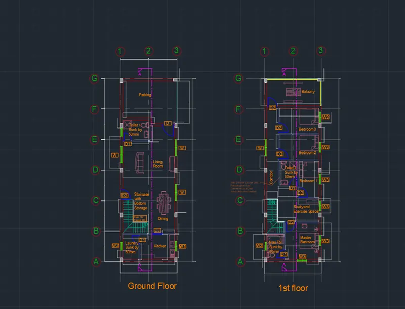
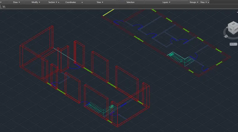
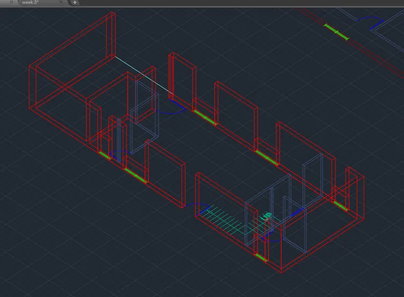
- I have attached some screenshots while plotting the needed Drawings to show the procedure on how it was done to come out with the requested Design layouts.
C. Command Used;
In general, below commands/functions were being used while working on the exercises.
- Units
- LIMMAX
- DDIM
- DI
- LINE
- XREF
- PASTECLIP
- OFFSET
- MLINE
- TRIM
- ERASE
- EXTEND
- DIM
- COPY
- POL
- REC
- JOIN
- C
- UCS
- EXTRUDE
- SWEEP
- LOFT
- UNION
- PRESSPULL
- REGION
- RENDER
- CAMERA
- LIGHTS
- MATERIAL
D. Assumptions: These were taken from Project 1 under Week 8.
- Window Sizes;
W = 1600 X 1200
W1 = 1000 X 1100
W2 = 800 X 600
W3 = 1000 X 1200
- Door Sizes;
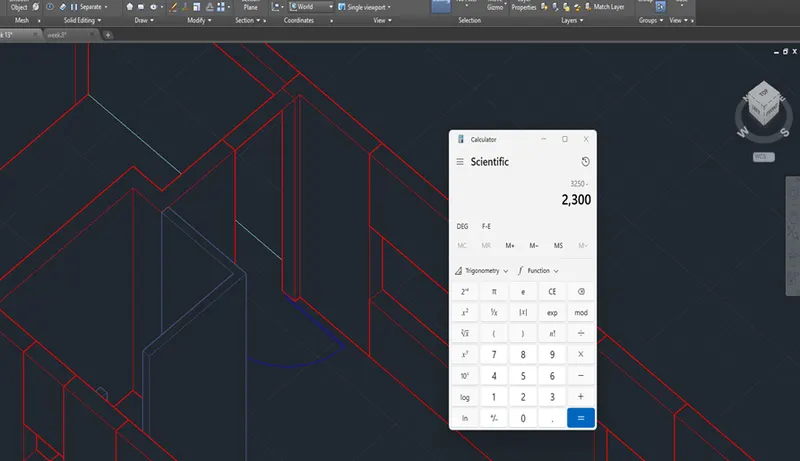
D = 1200 X 2300
D1 = 850X 2100
D2 = 1000 X 2200
D3 = 1000 X 2200 (wall opening only)
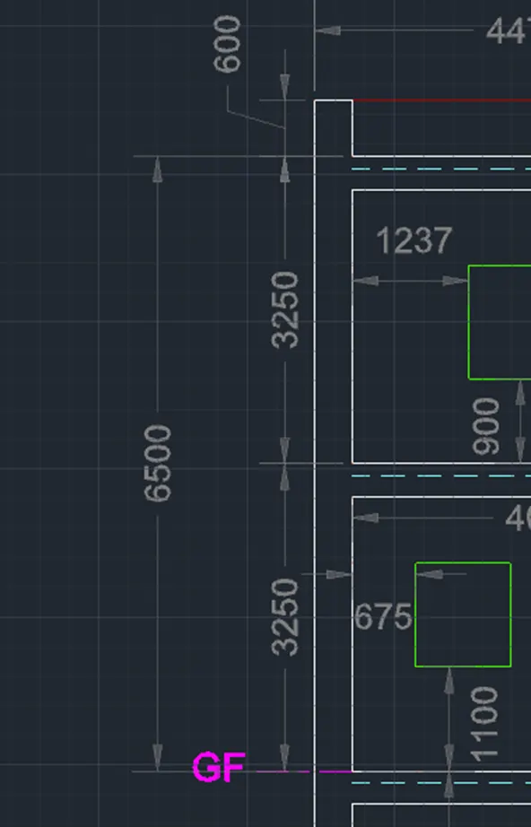
- Slab = 125mm Thick
- External Wal = 250mm Thick
- Internal Walls = 125 mm Thick
- Stairs = Riser is 180 and Thread is 250 with 1100 width including railings
- Floor to Floor elevation is 3250mm
E. Below are the brief steps while working on the requested design drawings;
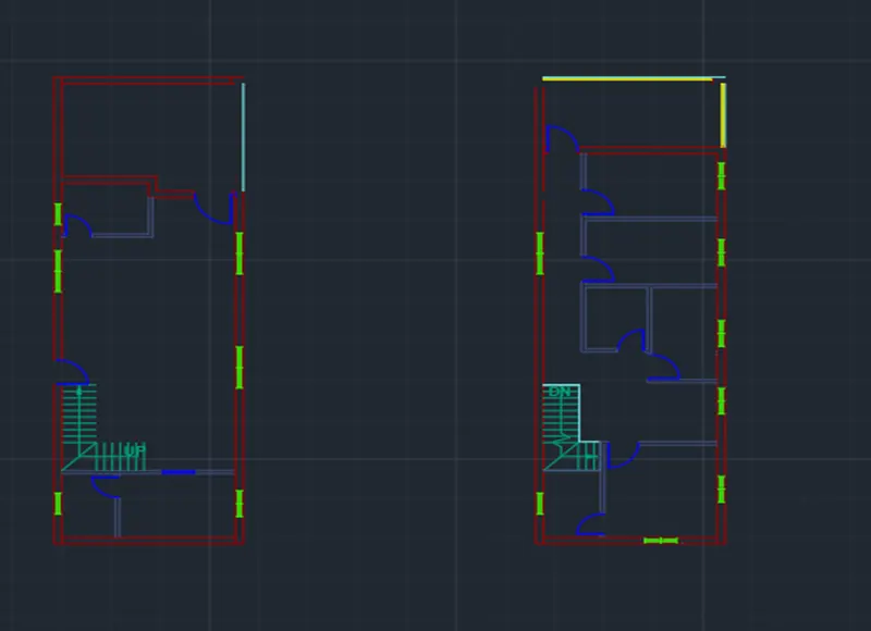
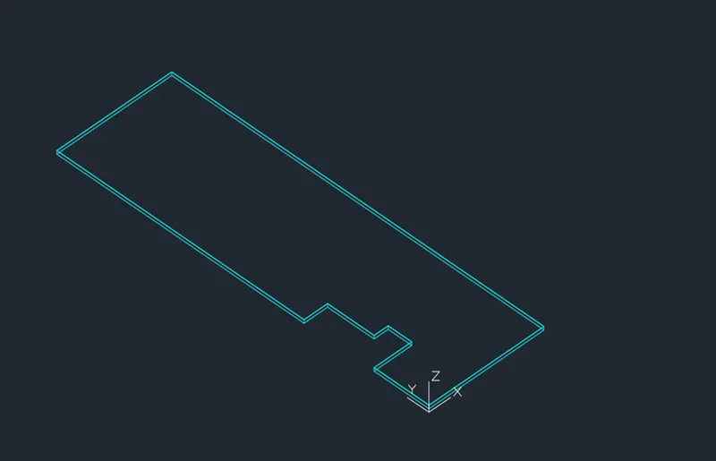
- With XREF or Pasteclip functions, extract the floor layout plans and any necessary 2d drawings created from Project 1 while on Top View.
- From that, set up the needed layers for the 3D version of the residential building such as 3D External/ Internal Walls, Windows, Doors, Stairs and etc.
- Start turning off layers from that XREF or Pasteclip objects which are not needed.
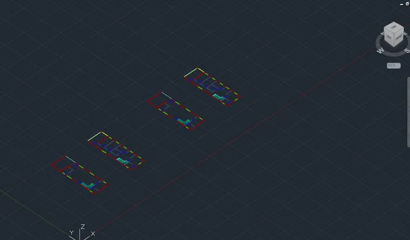
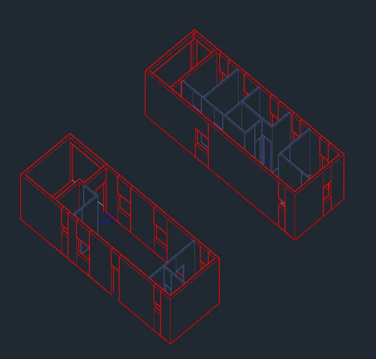
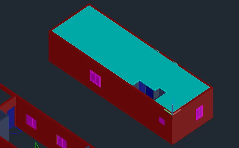
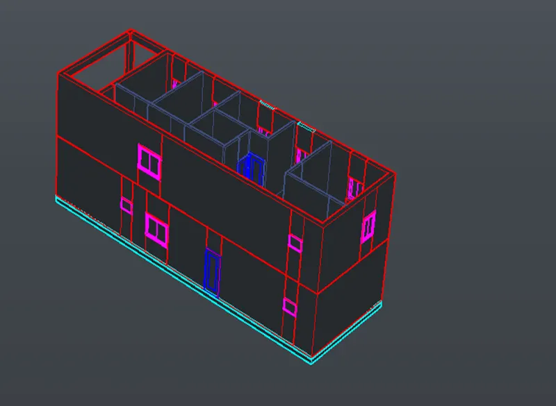
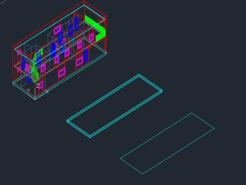
- On Isometric View, start establishing external and internal walls with the region/boundary and extrude commands using the floor plan and elevations coming from Project 1.
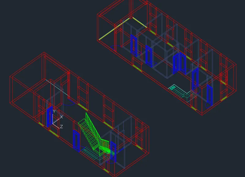
- Proceed with the door and window openings following the floor plan and elevation details of Project 1. Subtract command is needed here if necessary but most of the time not needed as you only needed to extrude the floor portion of the window opening the extrude to its sill level and top side will be creating rectangle between wall edge interval and extruding it down to the top level of the window.
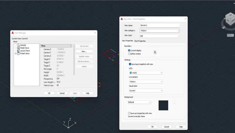
- Appropriate UCS orientations has to be followed at all time while working on 3D models and saved necessary views as possible.
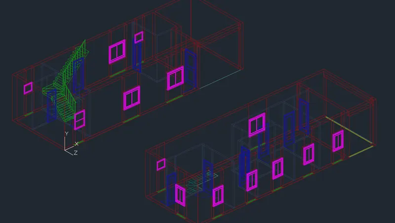
- Now proceed creation of the Window (following the dimensions of Project 1) out of rectangle, offset, trim, erase, boundary and subtract commands.
- Make a projection of the window using extrude on an assumed height/thickness just to project a 3D window. Work on subtract and repeat extrusion as needed or applicable.
- Create the window by manipulation of UCS orientation to the wall created and draw a temporary line to position the opening. Ensure proper dimensions are followed.
- Same steps of Window to follow in the creation of Doors.
- Openings will be created out of solid rectangle and subtract to the wall.
- Move or copy the created windows and doors to its location. You may also use 3DALGN command if not in the same plane with the walls or ROTATE3D as applicable.
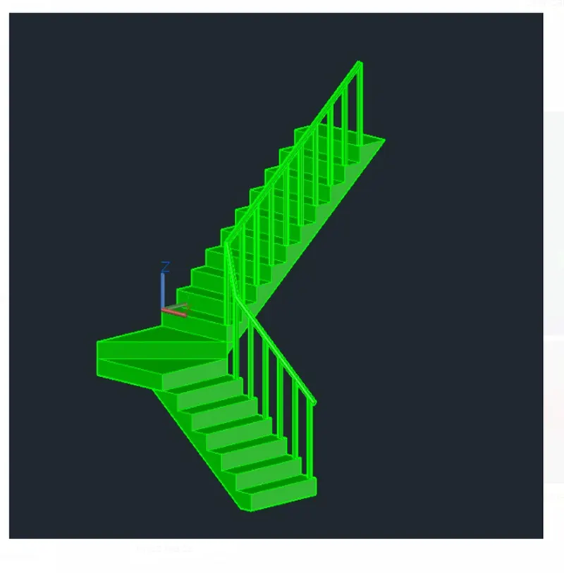
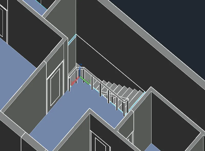
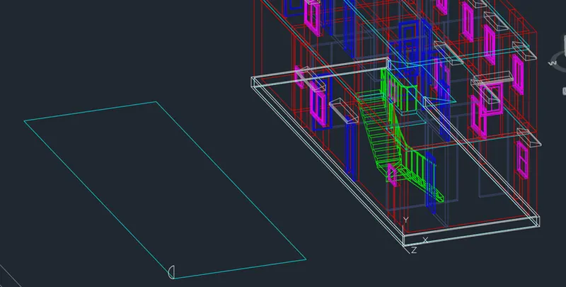
- Next is the creation of stairs. This can be created while in section view. Draw the stairs following the elevation dimension of 3250mm, stairs wide of 1100mm, thread of 250mm and 180mm riser.
- The stairs drawn from the 2D of Project 1 can also be a basis although it would be on 2 planes and connection each other. If drawn, this can be done by plotting the threads and risers on section view and doing its bottom side by making a parallel line connection all bottom edges and offsetting it. Follow by extension of lines of bottom part and top part of the stairs the trim command. You may make a region or boundary out of it and proceed with extrusion.
- Do the same steps for the upper portion of the stairs in a different section view. You may then connect with each other while also making sure proper landing is created.
- Proceed with the balustrades and handrails. Both can be created using a sweep command. First draw a circle or an object you want to sweep at size of your desire or as per the design and draw the path as a line or polylines. Please check the bottom screen shots for the completed stairs.
- Slabs or floors can now be created out of rectangle command following the path of external walls, make it a region or boundary and extrude it at a dimension inline with Project 1. Its best to start in level 1 floor considering the floor openings to give way for stairs.
- Proceed with the Railings connecting the stairs of level 1 before proceeding with the other floor or roof.
- Railings at the balcony can now be drawn with the same concept of what have done in stairs. It would be best to use the 3DARRAY command.
- Proceed with the other aesthetic features of the building such as the cladding on the bottom floor, canopy of selected windows and doors. This can be done with the draw object and extrude, sweep and path commands. It would be best to turn off layers which are not needed for the ease of operation of the needed functions.
- Position the completed 3D figure to its desirable view and proceed with the material assignment as applicable.
- Make a good or presentable rendering by considering camera views, light application, and related rendering options.