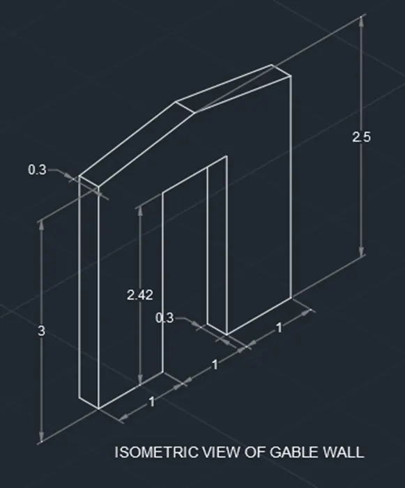
Creating a Floor plan, Footing detail and Isometric view using AutoCad
Week 2-Assignment 2-Module 2
Aim: To sketch and edit the requested geometries using the different drawing and modifying tools covered in week 2 sessions.
Introduction:
- The topics covered in week 2 which are essentials in plotting the requested geometries are as follows;
- Drawing Rectangles in AutoCAD, rectangle is a quadrilateral polygon with four right angles. Plotting it in AutoCAD can be done in different ways as below;
- Ribbon : Home>Draw>Rectangle
- Toolbar: Draw>Rectangle
- Tool Palettes: Draw>Rectangle
- Command: RECTANG
- Also enabling rectangle in AutoCAD will also leads you to many options as needed with your requirements in plotting the rectangle. Options such as Chamfer, Elevation, Fillet, Thickness and Width depending on how you want your rectangle will look like with your provided parameters.

- Drawing Polygons in AutoCAD, is a plane figure that is described by a finite number of straight-line segments connected to form a closed polygonal chain. Plotting it in AutoCAD can be done in different ways as below;
- Ribbon : Home>Draw>Polygon
- Toolbar: Draw> Polygon
- Tool Palettes: Draw> Polygon
- Command: POLYGON
- Also enabling polygon in AutoCAD will leads you to many options as needed with your requirements in plotting the polygon. Options such as inscribed in circle, circumscribed about circle or through selecting Edge which will prompt in providing the entry points of firs sides of the polygon and rest to generate automatically following to that. This after you have given how many sides of polygon you want.
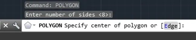
- Drawing Polylines in Auto CAD, a polygonal chain is a connected series of line segments. Once drawn, it is considered as one object unlike when you draw it using the normal line drawing tool. Plotting it in AutoCAD can be done in different ways as below;
- Ribbon : Home>Draw>Polyline
- Toolbar: Draw> Polyline
- Tool Palettes: Draw> Polyline
- Command: PLINE or PL
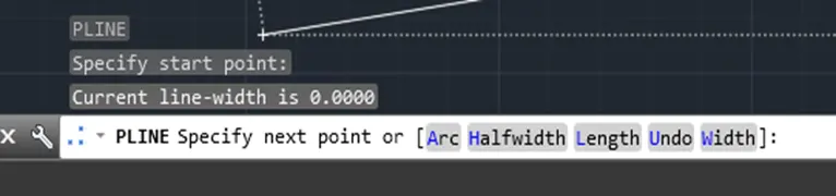
- Once you’ve entered the starting point of polyline, it will leads you to many options as needed with your requirements in plotting the polyline.
- Moving Sketched Objects, this will enable you to move the plotted objects or figure as what location you want. This can be done in different ways as below;
- Ribbon : Home>Modify>Move
- Toolbar: Modify> Move
- Command: M
- Copying Sketched Objects, this will enable you to replicate the plotted objects or figure in to what location you want either single or multiple. This can be done in different ways as below;
- Ribbon : Home>Modify>Copy
- Toolbar: Modify> Copy
- Command: CO
- Copy tool also will prompt you to have an option of Array which you can create copies of objects depending on how many numbers you want and evenly spaced to a location desired.
- Creating an Array of Selected Objects, Array will let you create copies of objects arranged in a pattern either rectangular, polar, or path and evenly spaced with each other. This can be done in different ways as below;
- Ribbon : Home>Modify>Array
- Toolbar: Modify> Array
- Command: AR
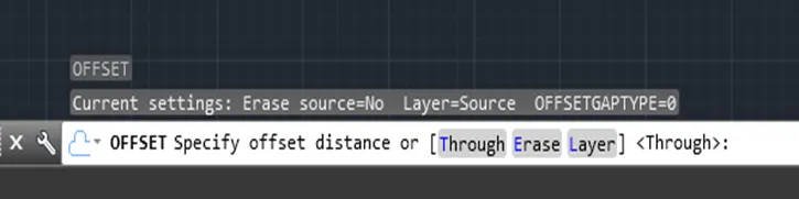
- Offsetting Sketched Objects, Offset is used to create parallel lines, concentric circles, and parallel curves in a determined distance. This can be done in different ways as below;
- Ribbon : Home>Modify>Offset
- Toolbar: Modify> Offset
- Command: O
- It has also many options such as deleting the original object after the offset command is done.
- Rotating Sketched Objects, this command is used to rotate the object by an absolute angle. It has also a copy option to retain the object from its original position and that only the copied version is rotated to its designated angle. This can be done in different ways as below;
- Ribbon : Home>Modify>Rotate
- Toolbar: Modify> Rotate
- Command: RO
- Scaling Sketched Objects, this is like a tool that will let you increase or decrease a certain object percentage wise. It has also a copy option to retain the object from its original position and that only the copied version is scaled up or down. This can be done in different ways as below;
- Ribbon : Home>Modify>Scale
- Toolbar: Modify> Scale
- Command: SC
- Filleting the Sketched Objects, used to create rounded edges between the adjacent lines and also works on arcs. This can be done in different ways as below;
- Ribbon : Home>Modify>Fillet
- Toolbar: Modify> Fillet
- Command: FILLET
- It has also many options such as below.

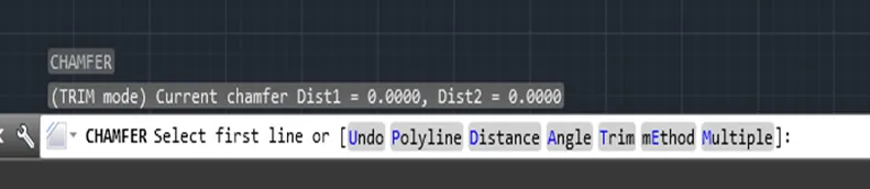
- Chamfering the Sketched Objects, this command is used to create slanted edges.
- Ribbon: Home>Modify>Chamfer
- Toolbar: Modify> Chamfer
- Command: CHA
- It has also many options such as below.
- Drafting Settings Dialog Box, here users can modify drafting settings such as Snap & Grid, Polar Tracking, Objects Snap, 3D Object Snap, Dynamic Input, Quick Properties & Selection Cycling. You can enable this by going to the Toolbars or through DS command.
- also covered on this are the usage of ortho and snap tools, the object snap settings, gridlines and isoplane.
- In ortho mode, it will restrict your action movement to horizontal or vertical only at 90 degrees. This is very ideal specially for direct distance entry method of plotting a lines.
- Snap Model will put constraint on your cursor on a movement as per the Snap settings. It is ideal that Snap and Grid are set up in harmony.
- Isoplane allows you to easily draw at a 30 degree angle as needed for an isometric drawing.
Procedure:
A. Starting AutoCAD;
- Search for the AutoCAD icon from your desktop and double click it to make it run or you may search it from windows search tool and open from there if no shortcut in the desktop.
- You may simply click the “Get Started-Start Drawing” icon once the AutoCAD is opened or you may click the Application Menu tab with the “A” AutoCAD logo on the top -left most side of the screen and select new. From the new you may find a variety of templates that suits your requirements.
- For this exercise, we will just simply proceed on Get Started-Start Drawing” icon and set up the measurement units inline with the drawing requirements.
B. Setting the Drawing Parameters;
- Set up the measurement units according to sketched information provided.
- To set up that, a much faster way is to type “units” in the command line and hit enter or space bar. The Drawing Units Dialog box will then pop up and measurement parameters will then set up in line with the requirements. Similar thing, you need to set up the dimension through the DDIM command.
- As for the gridlines, you may right click gridline icon in the status bar and go for the drafting settings. Under the Snap and Grid of the Drafting Settings Dialog box, you may set up the needed spacing of grids along its X and Y axis. “DS” command will also work to pop up the Drafting Settings Dialog box. As for the isoplane mode, you can enable it from the Status bar line.
C. Starting the exercise;
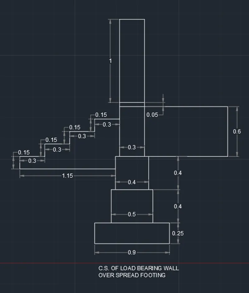
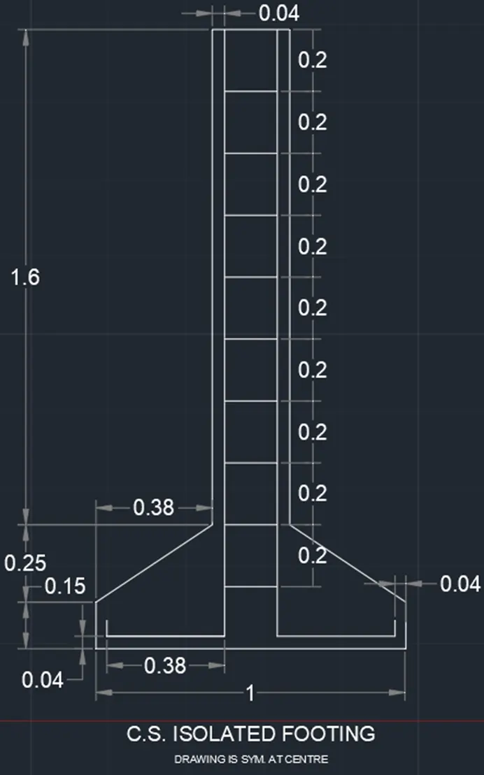
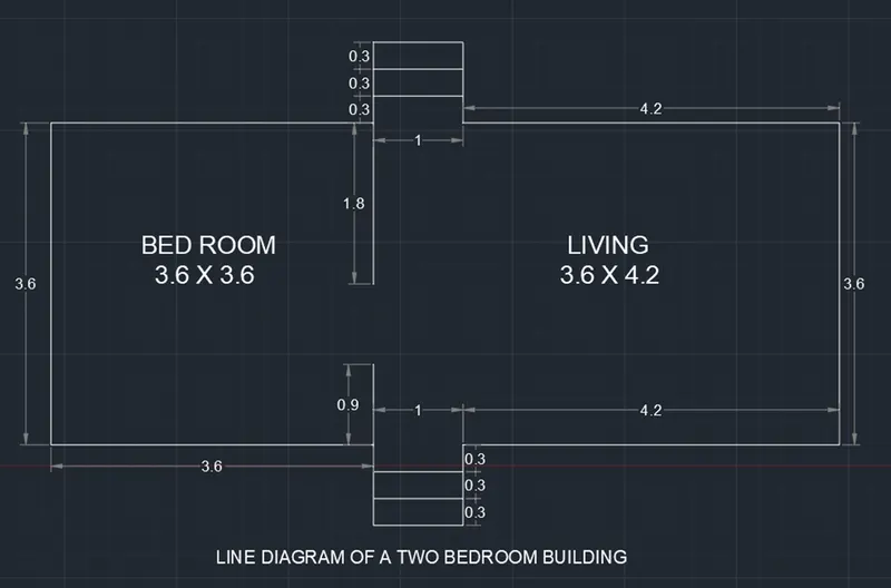
- Combination and manipulation of all the different coordinate entry methods, drawing and modifying tools learned from weeks 1 and 2 are being used here in the completion of all the exercises given and result as pasted below.
- I believe we don’t need to write each and every step here in submitting the AutoCAD challenges. Important thing is we know how to draw it correctly and we can present it in a report format if needed.
C1
C2
C3
C4
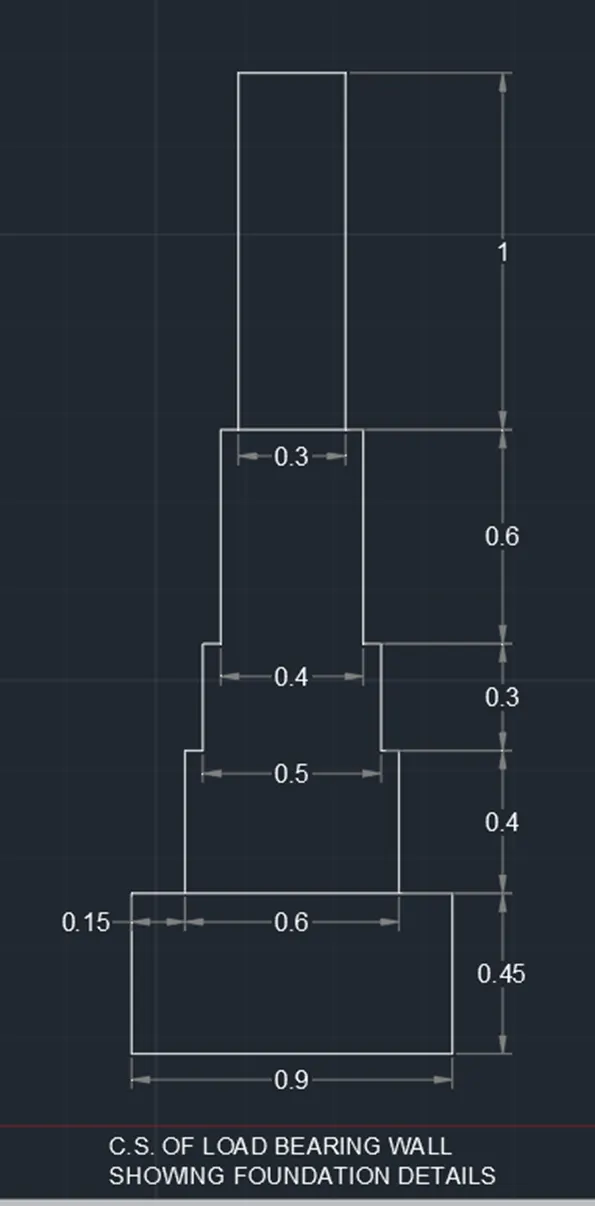
C5
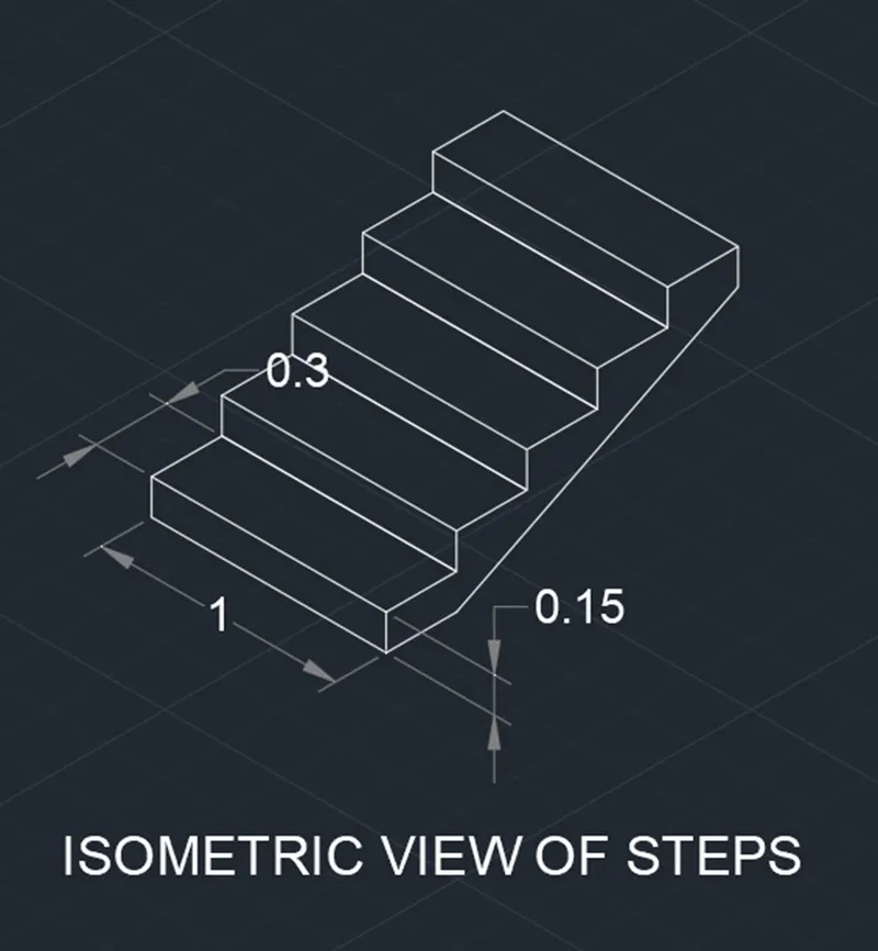
C6