Creation of geometries by Coordinate system methods using AutoCad
Week 1-Assignment 1-Module 2
Aim: To create the requested geometries using the different coordinate system entry methods available in AutoCAD. Combination of line and circle tools shall be used as applicable.
Introduction:
A. AutoCAD – is a computer aided design and drafting software application developed and owned by Autodesk. It is a tool that is widely used in Construction Industry by Architects, Engineers, Contractor, Designers etc.
B. The different coordinate entry methods in plotting geometries in AutoCAD are;
I. Absolute coordinate – or absolute cartesian coordinates specify a point’s exact distance from the origin point of the coordinate system, which is represented as (0,0). The absolute X and Y coordinates are signed numbers.
II. Relative coordinates –
- Relative rectangular coordinates – or relative cartesian coordinates specify a point’s exact distance from the last point that was entered. The X and Y coordinates are signed numbers. For example, typing @10,5 tells AutoCAD to locate to a point that is ten X units and 5 Y units away from the last point entered. The X and Y relative coordinates are signed numbers.
- Relative polar coordinates – specify a point’s exact location by a distance and angle from the last point that was entered. The distance is always positive and the angle is measured from the X-axis. For example, typing @10,90 tells AutoCAD to locate to a point that is ten units away from the last point entered and at an angle 90 degrees from the horizontal.
III. Direct distance entry – this is just a simple shorthand for relative coordinate entry method. For example, dragging the cursor to a certain direction and typing 10 will give you ten units away from the last point entered and at an angle with respect to the direction of your cursor when you dragged it.
C. Usually, combination of the 3 coordinate entry methods are being used to suit the tasks at hand. It usually depends on how to expedite the drafting works by not also sacrificing its accuracy.
Procedure:
A. Starting AutoCAD;
- Search for the AutoCAD icon from your desktop and double click it to make it run or you may search it from windows search tool and open from there if no shortcut in the desktop.
- You may simply click the “Get Started-Start Drawing” icon once the AutoCAD is opened or you may click the Application Menu tab with the “A” AutoCAD logo on the top -left most side of the screen and select new. From the new you may find a variety of templates that suits your requirements.
- For this exercise, we will just simply proceed on Get Started-Start Drawing” icon or use the Imperial Template if applicable.
B. Setting the Drawing Parameters;
- As needed in this exercise, measurement will be in imperial system and in decimal units.
- To set up that, a much faster way is to type “units” in the command line and hit enter or space bar. The Drawing Units Dialog box will then pop up and measurement parameters will then set up in line with the requirements.
- As for the gridlines, you may right click gridline icon in the status bar and go for the drafting settings. Under the Snap and Grid of the Drafting Settings Dialog box, you may set up the needed spacing of grids along its X and Y axis. “DS” command will also work to pop up the Drafting Settings Dialog box.
C. Starting the exercise;
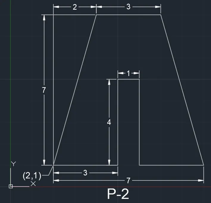
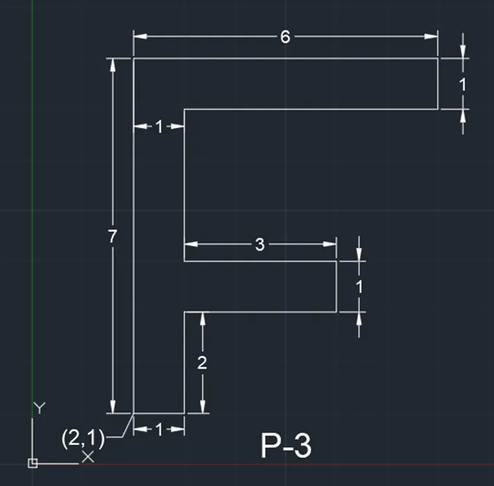
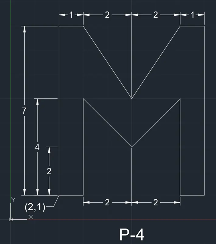
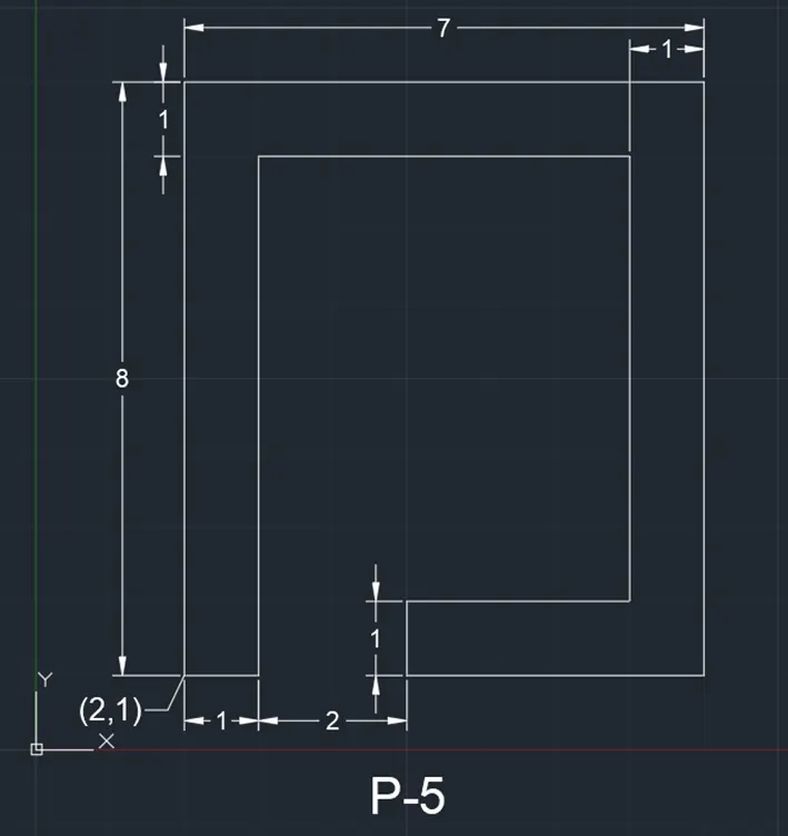
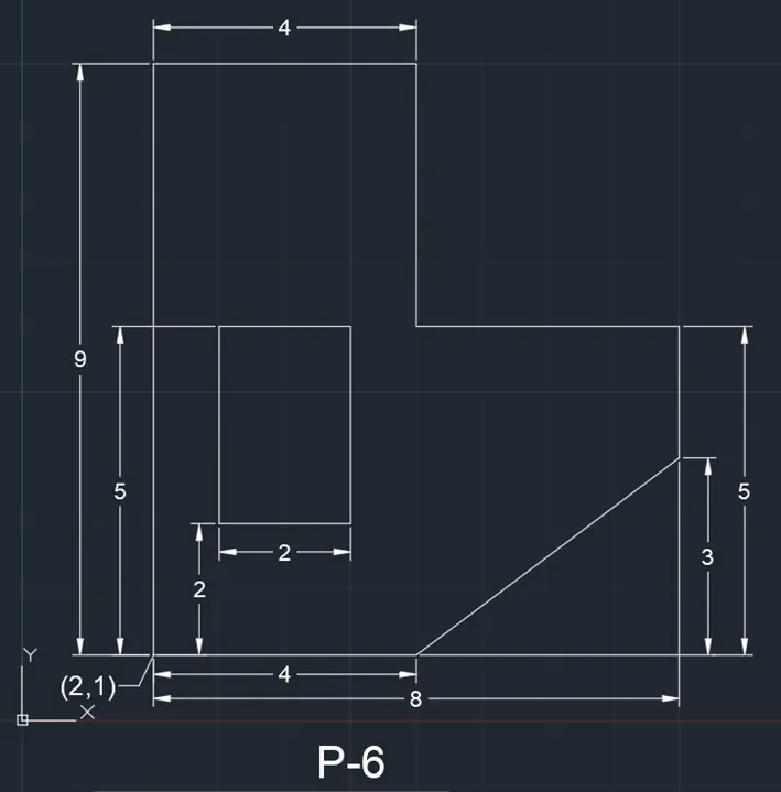
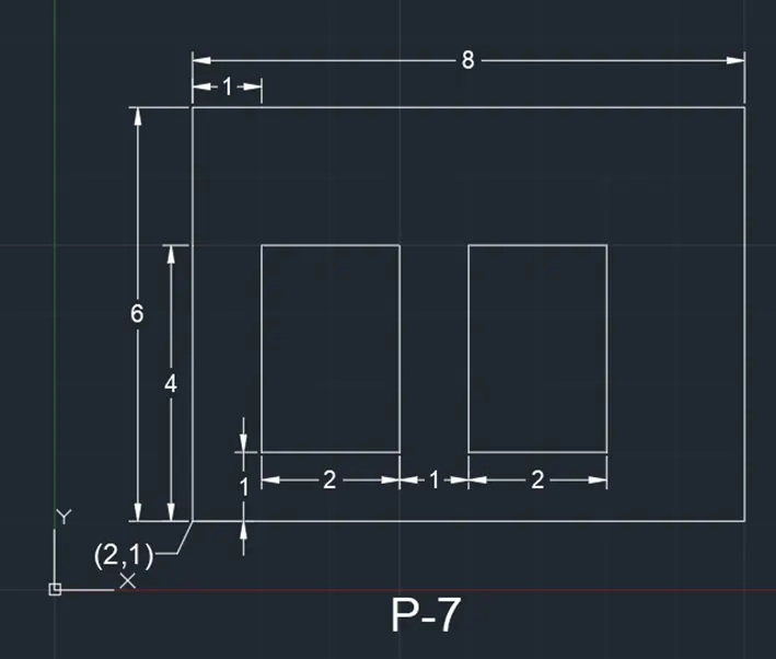
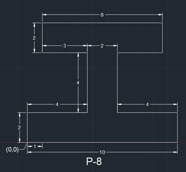
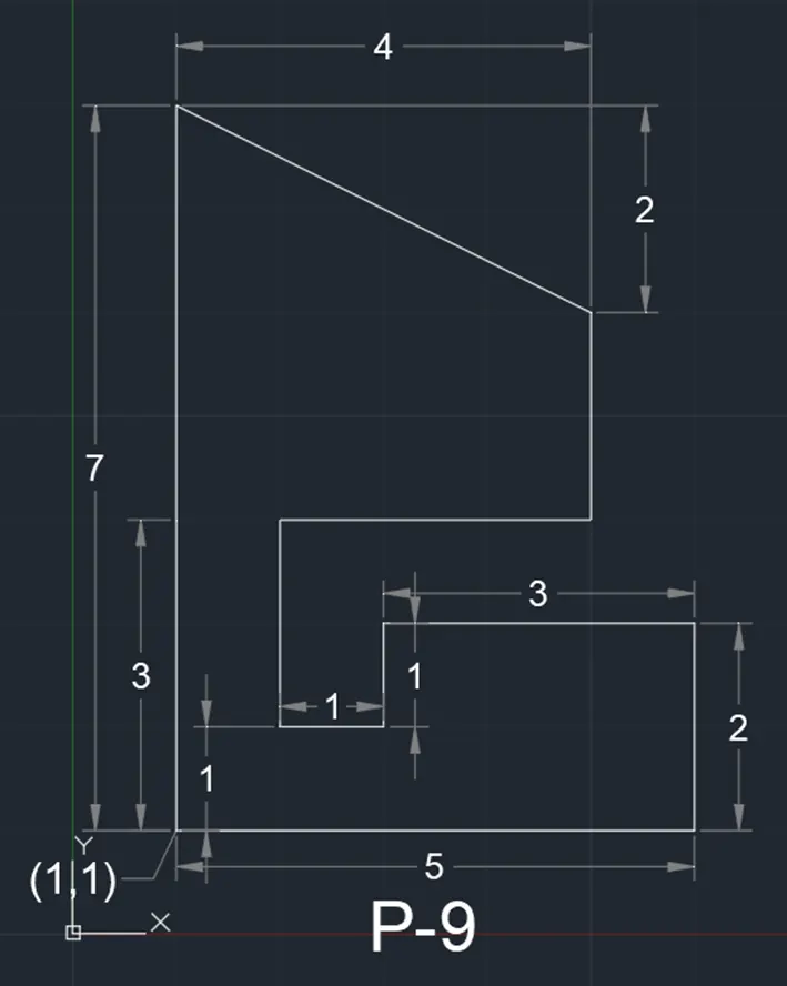
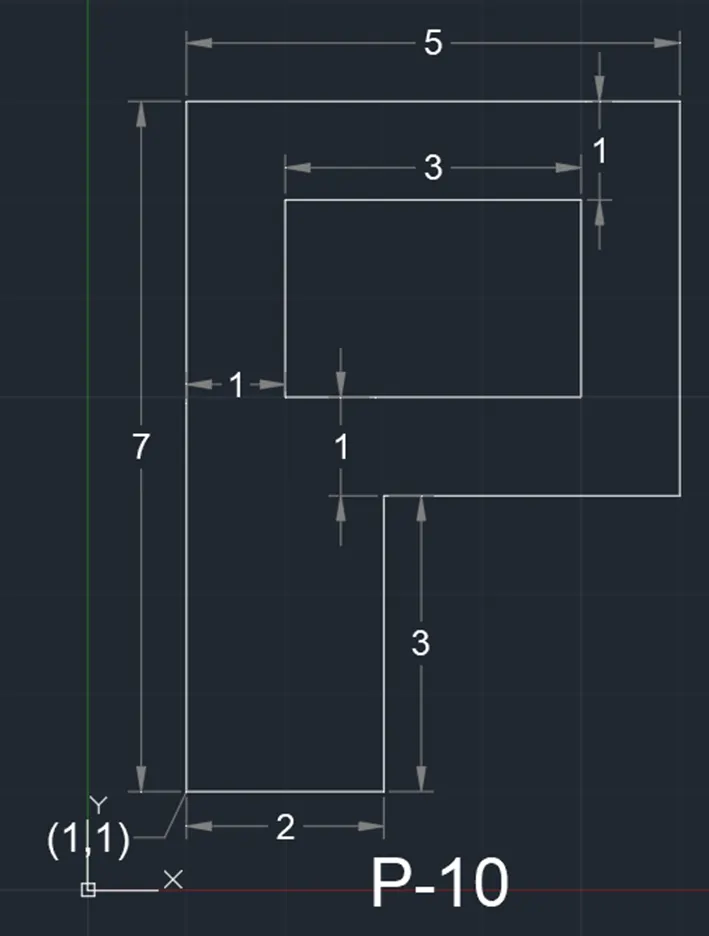
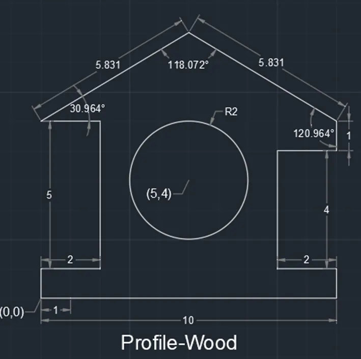
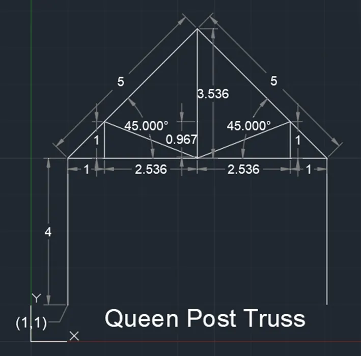
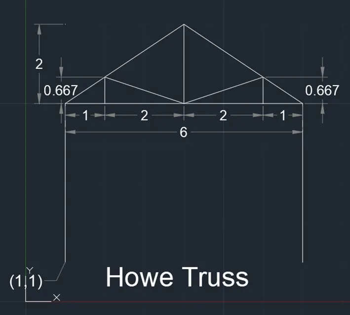
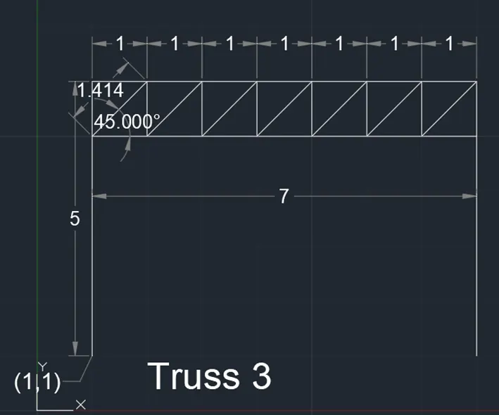
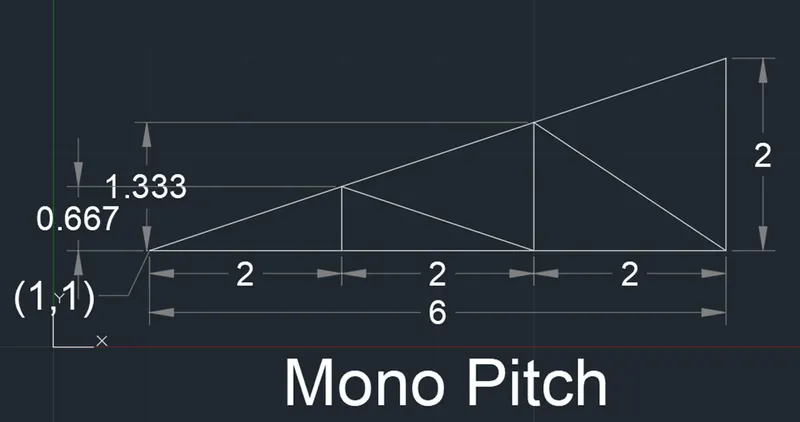
- Combination and manipulation of all the different coordinate entry methods are being used here in the completion of all the exercises given and result as pasted below including the Civil related problems ones.
- In the Civil related problems, the Combination of line and circle tools were used specially in plotting the “Profile-Wood” exercise.
D. As a sample, this what I did in plotting the requested geometries;
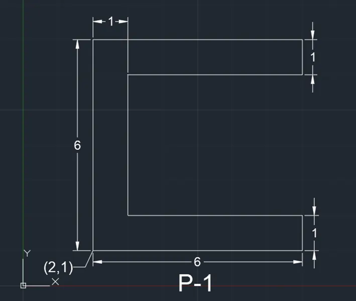
- P-1 : Started with Absolute coordinate and followed by Direct distance entry.
- Type L in command line and hit enter or space bar
- Type 2,1 and hit enter or space bar
- Drag the cursor horizontally (straight line) to the right and type 6 and hit enter or space bar
- Drag the cursor vertically (straight line) up and type 1 and hit enter or space bar
- Drag the cursor horizontally (straight line) to the left and type 5 and hit enter or space bar
- Drag the cursor vertically (straight line) up and type 4 and hit enter or space bar
- Drag the cursor horizontally (straight line) to the right and type 5 and hit enter or space bar
- Drag the cursor vertically (straight line) up and type 1 and hit enter or space bar
- Drag the cursor horizontally (straight line) to the left and type 6 and hit enter or space bar
- Then type C as closed hit enter or space bar
- Tips: Turning on the orthomode when doing Direct distance entry is also preferred to avoid any mistakes for this exercise (though this is not yet covered by this exercise)
- Rest of exercises are just simply manipulation of all the available methods and tools covered by this week’s sessions. You may refer to the results of the exercises as pasted below.