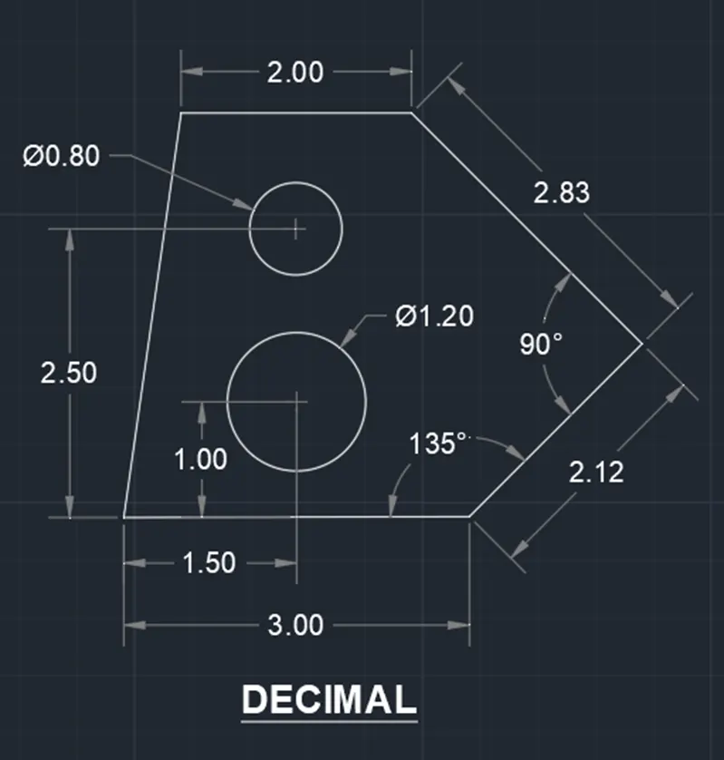
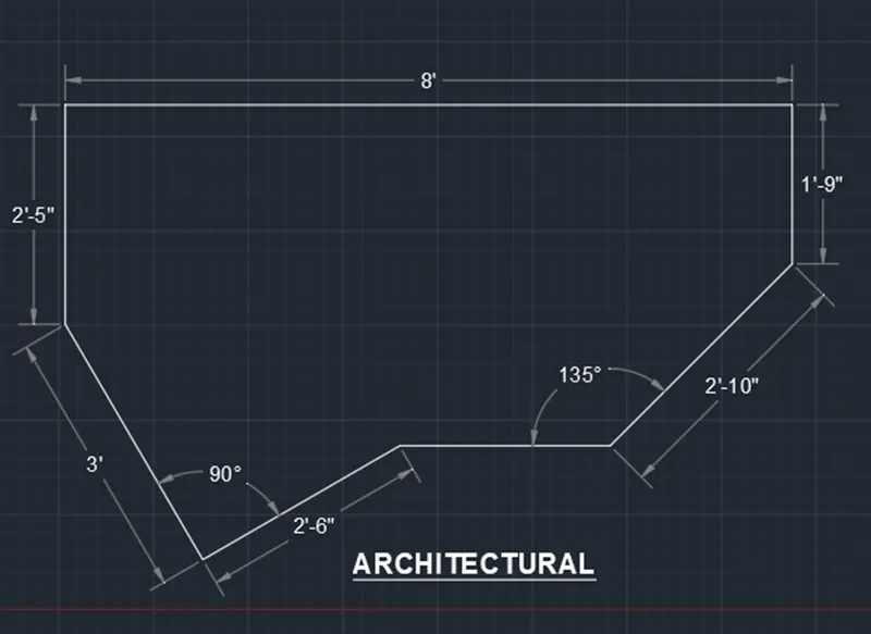
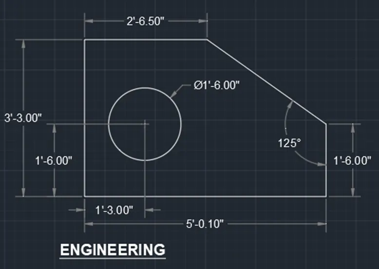
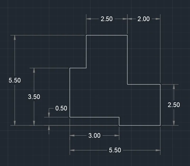
Drafting of various geometries using Chamfer, Fillet tool in AutoCad
Week 3-Assignment 3-Module 2
Aim: To sketch and edit the requested geometries using the different drawing and modifying tools covered in week 3 sessions.
Introduction:
- The topics covered in week 3 (titled Start Advanced Sketching and Editing I) which are essentials in plotting the requested geometries are as follows;
- Working with Object Snap (OS), OS is used to specify a precise location on the objects. It displays the points on the objects, such as midpoints, center point, quadrant point, insertion point, endpoint, etc., which make the drafting and drawing process effective. It can be edited or enabled in many different ways such as below;
- Command: DS, will pop out the Drafting Settings Dialog Box where OS tab is part of it. From there you can organize your OS settings.
- Command: OS, will prompt you directly to Drafting Settings Dialog Box with pre-selected OS tab.
- From the status bar itself you can find the OS Snap icon
- You can enable / disable OS directly by pressing F3.
- Create Elliptical Objects, Ellipse is defined as a curve surrounding two focal points. The shape of the ellipse is determined by two of its axis, which defines the length and width. Plotting it in AutoCAD can be done in different ways as below;
- Ribbon : Home>Draw>Elliptical Arc or Ellipse
- Toolbar: Draw> Elliptical Arc or Ellipse
- Tool Palettes: Draw> Elliptical Arc or Ellipse
- Command: ELLIPSE

- Create Arcs, it is defined as the smooth curve formed by joining two or more points. Plotting it in AutoCAD can be done in different ways as below;
- Ribbon : Home>Draw>Arc
- Toolbar: Draw> Arc
- Tool Palettes: Draw> Arc
- Command: ARC
- Also there are many variations of methods on how you are going to plot the arc depending on the drawing situation and requirements. Such variations like Start-Center-End, 3 points, Start-End-Angle etc.
- Insert Multiple points, in geometry, a point is a location represented by a dot. A point does not have any length, width, shape or size, it only has a position. Plotting it in AutoCAD can be done in different ways as below;
- Ribbon : Home>Draw>Point or Multiple Points
- Toolbar: Draw> Point or Multiple Points
- Tool Palettes: Draw> Point or Multiple Points
- Command: POINT
- You can edit its style through PTYPE or DDPTYPE commands.
- Use Divide and Measure Tools, Divide will create evenly spaced points or blocks along an object, while Measure do the same, but each will be a fixed distance apart. You can access such tools in different ways as below;
- Ribbon: Home>Draw>Divide or Measure
- Toolbar: Draw> Divide or Measure
- Tool Palettes: Draw> Divide or Measure
- Command: DIVIDE or MEASURE, depends on what you want
- Construction and Ray Lines, construction line (also known as an xline) is a linear object that passes through two points and extends to infinity in both directions. A ray is a linear object starts at a point, passes through a second point, and extends to infinity. They are useful as they can be used as references for creating other objects. You can access such tools in different ways as below;
- Ribbon: Home>Draw>Construction Line or Ray
- Toolbar: Draw> Construction Line or Ray
- Tool Palettes: Draw> Construction Line or Ray
- Command: XL or RAY, depends on what you want
- Use Donut Tools, Donuts are filled rings or solid-filled circles that are actually closed polylines with width. Plotting it in AutoCAD can be done in different ways as below;
- Ribbon : Home>Draw>Donut
- Toolbar: Draw> Donut
- Tool Palettes: Draw>Donut
- Command: DO
- Use Modify Tools such as:
- Mirror, is used to create a copy (mirror copy) of the selected object. We can also delete the source object after mirroring the object as well as mirror it at a certain axis with a certain distance from the source object. This can be done in different ways as below;
Ribbon: Home>Modify>Mirror
Toolbar: Modify> Mirror
Command: MI
- Trim, is used to remove the objects, which meet the edges of other objects. It is used to remove extra lines or extra parts of an object. We can also perform trim using different selection methods. We are required to select the portion of the object to trim. This can be done in different ways as below;
Ribbon: Home>Modify>Trim
Toolbar: Modify> Trim
Command: TR
- Extend, is used to extend the selected boundaries or edges. The objects are extended so that the edges of other objects can be converged. Also it comes with many modifying options. This can be done in different ways as below;
Ribbon: Home>Modify>Extend
Toolbar: Modify> Extend
Command: EX
- Explode, this is being used when you want to disassociate all parts of a compound object so that you can modify its components separately. Objects that can be exploded include blocks, polylines, and regions, among others. This can be done in different ways as below;
Ribbon: Home>Modify>Explode
Toolbar: Modify> Explode
Command: X
- Lengthen, it changes the length of objects and the included angle of arcs. You can specify changes as a percentage, an increment, or as a final length or angle. LENGTHEN is an alternative to using TRIM or EXTEND. This can be done in different ways as below;
Ribbon: Home>Modify>Lengthen
Toolbar: Modify> Lengthen
Command: LEN
- Break, you can create a gap between two specified points on an object, breaking it into two objects. If the points are off of an object, they are automatically projected on to the object. Break can by space or by a point. This can be done in different ways as below;
Ribbon: Home>Modify>Break or Break at Point
Toolbar: Modify> Break or Break at Point
Command: BREAK
- Join, is used to join the objects end to end to create a single object. The objects can be curved or linear, depending on the requirements. This can be considered also as the opposite of Explode. This can be done in different ways as below;
Ribbon: Home>Modify>Join
Toolbar: Modify> Join
Command: J
Procedure:
A. Starting AutoCAD;
- Search for the AutoCAD icon from your desktop and double click it to make it run or you may search it from windows search tool and open from there if no shortcut in the desktop.
- You may simply click the “Get Started-Start Drawing” icon once the AutoCAD is opened or you may click the Application Menu tab with the “A” AutoCAD logo on the top -left most side of the screen and select new. From the new you may find a variety of templates that suits your requirements.
- For this exercise, we will just simply proceed on Get Started-Start Drawing” icon and set up the measurement units inline with the drawing requirements.
B. Setting the Drawing Parameters;
- Set up the measurement units according to sketched information provided.
- To set up that, a much faster way is to type “units” in the command line and hit enter or space bar. The Drawing Units Dialog box will then pop up and measurement parameters will then set up in line with the requirements. Similar thing, you need to set up the dimension through the DDIM command.
- As for the gridlines, you may right click gridline icon in the status bar and go for the drafting settings. Under the Snap and Grid of the Drafting Settings Dialog box, you may set up the needed spacing of grids along its X and Y axis. “DS” command will also work to pop up the Drafting Settings Dialog box. As for the isoplane mode, you can enable it from the Status bar line.
C. Starting the exercise;
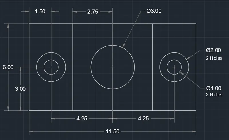
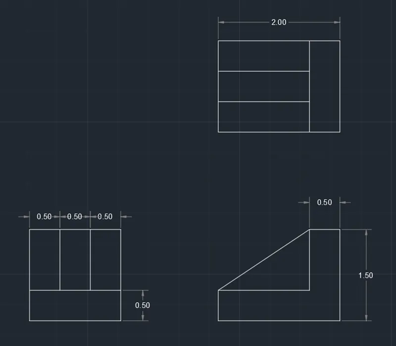
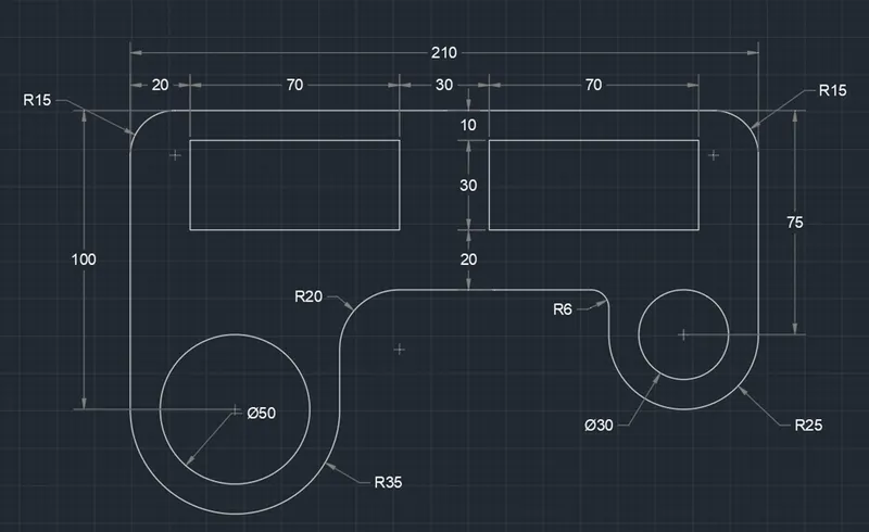
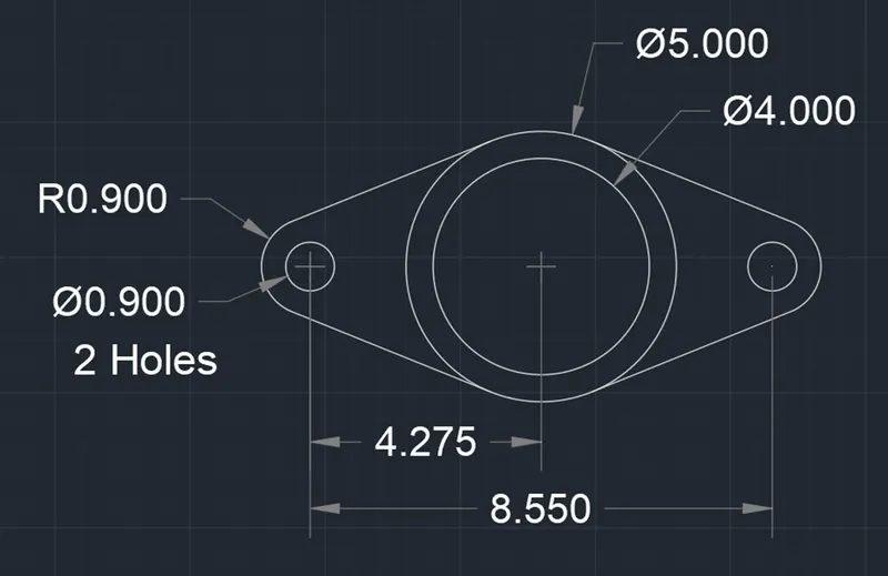
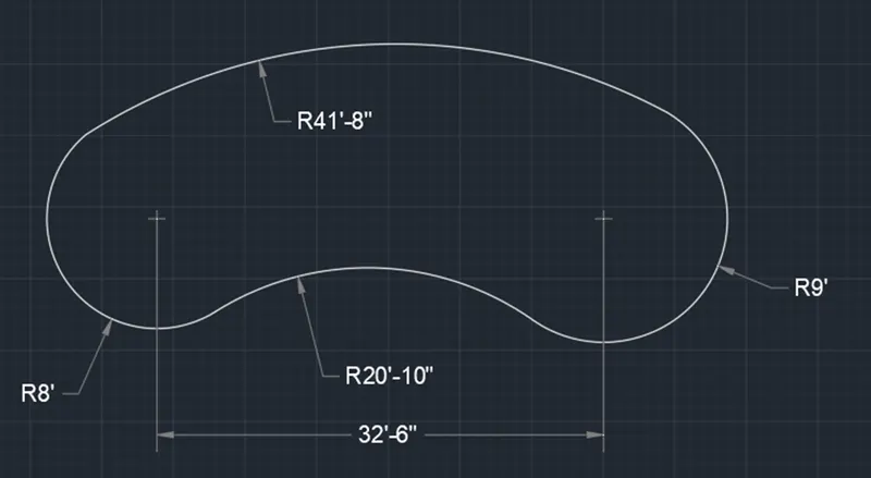
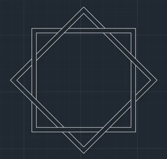
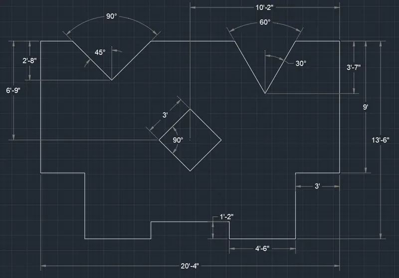
- Combination and manipulation of all the different coordinate entry methods, drawing and modifying tools learned from weeks 1 to 3 are being used here in the completion of all the exercises given and result as pasted below.
- I have attached a video presentation as a sample to one of the exercises to show the procedure on plotting the geometries requested.
- It seems video is not acceptable as an attachment. I will create a ticket for this.