Project 2_Creating a 3D rendered model for a Residential Building in AutoCad
AIM
To create a 3 dimensional model of the residential building with a rendered view
INTRODUCTION
Here we are using 3D modeling in AutoCAD
Tools used in 2d modeling are also used in 3D modeling
The special tools used in 3D modeling are
3DROTATE
3DORBIT etc..
Here we are drawing a G+1 residential building
We are using render option in AutoCAD
We can can provide material in the matrial browser
After applying materials to all the elements we render the drawing
PROCEDURE
Step 1:Draw the plan and elevation using line tool
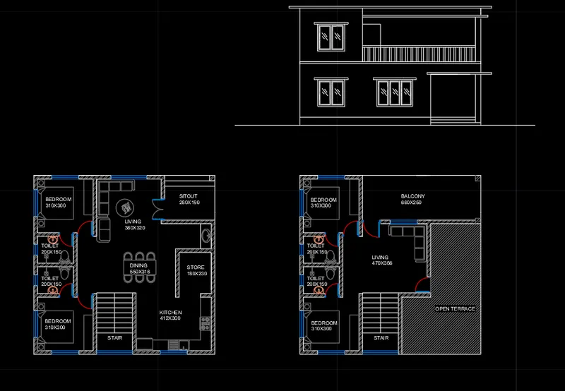
Step 2:Change the workspace into 3D modeling
Step 3:Using boundary option select the region to draw wall
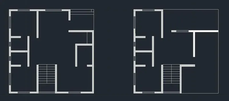
Step 4:Enter extrude command, select the area
Enter the value 3m
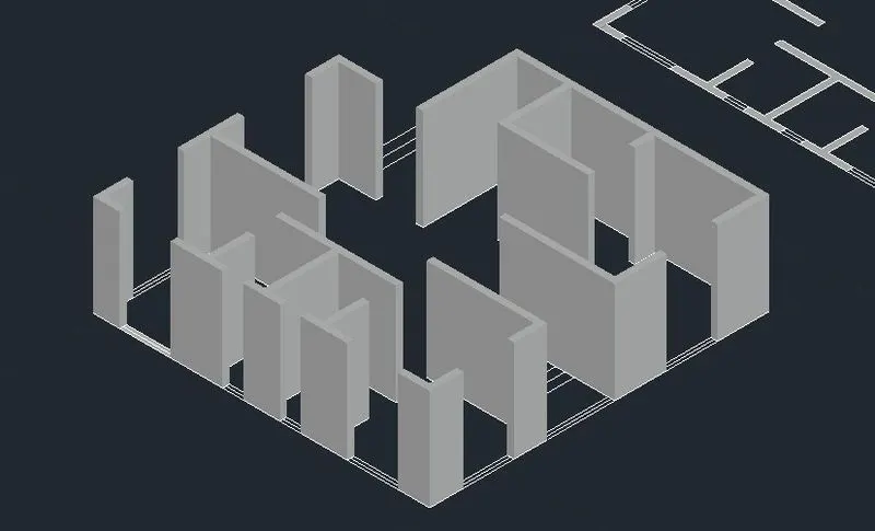
Step 5:Using region command select the region to draw the sill and upper portion of window
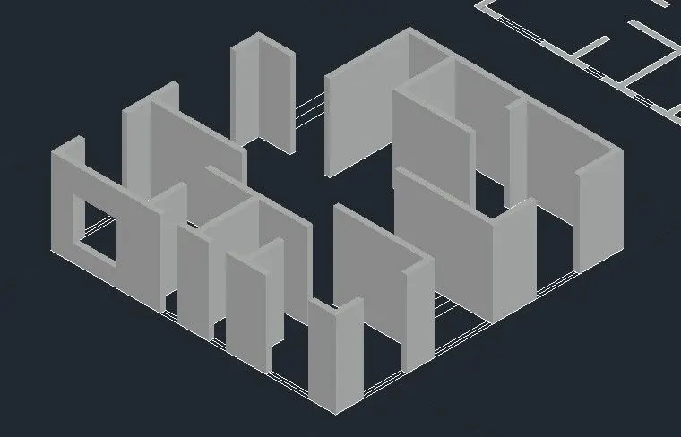
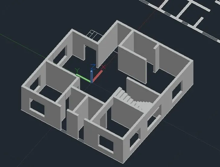
Step 6:Using rectangular tool draw the ground floor roof
Select the area using region tool
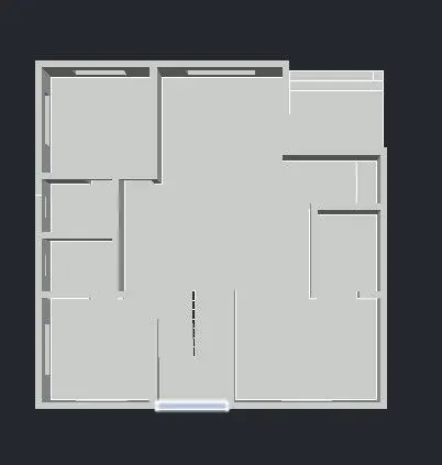
Step 7:Extrude the area
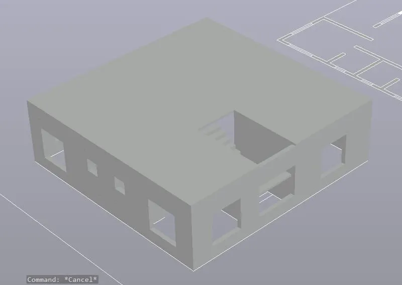
Step 8:Also draw floor area
Select the the area using region tool and extrude the area to 10 cm
Step 9:Draw the step using rectangular tool
Select the area using boundary option
Extrude first step to 15cm
Second step to 30cm
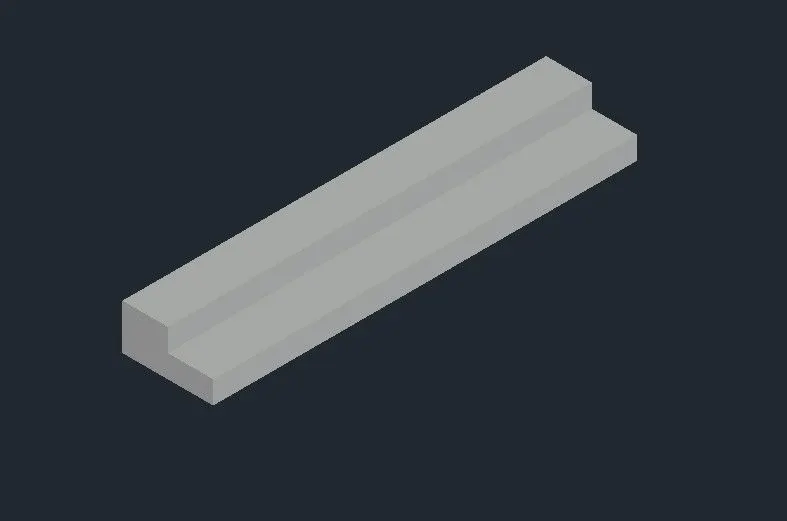
Step 10:Select the first floor wall area using boundary option
Extrude the area to 3m height
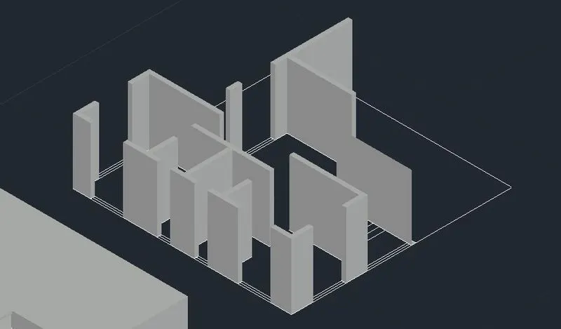
Step 11:Place the wall above ground floor using elevation
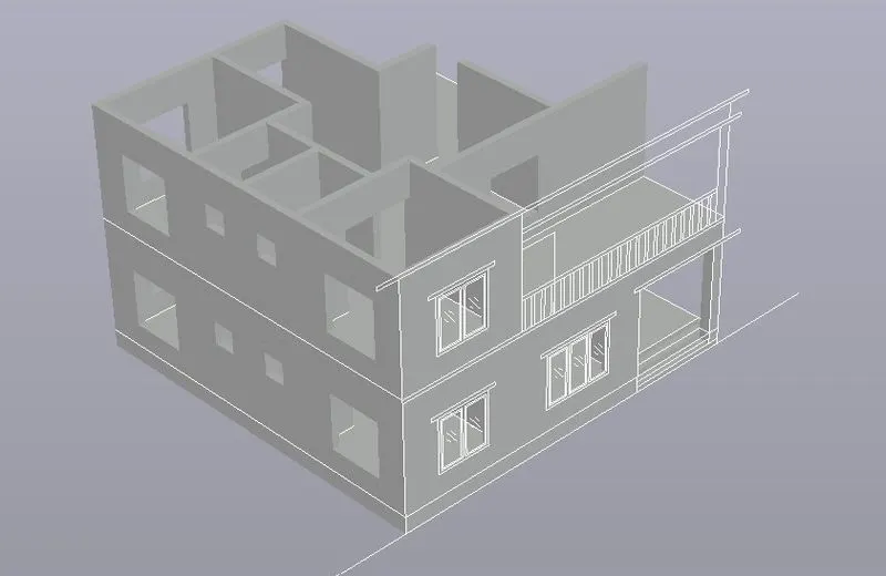
Step 12:Draw the first floor slab area using plan and elevation
Select the area using boundary option
Extrude the area to 10cm
Draw the slab for balcony

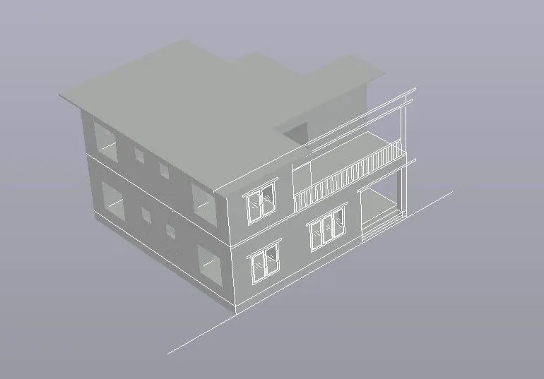
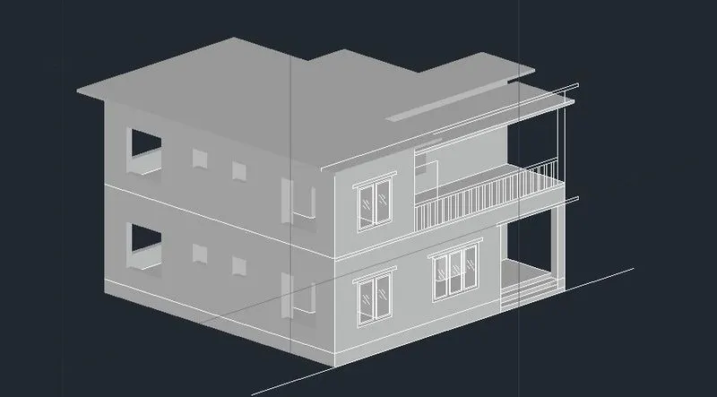
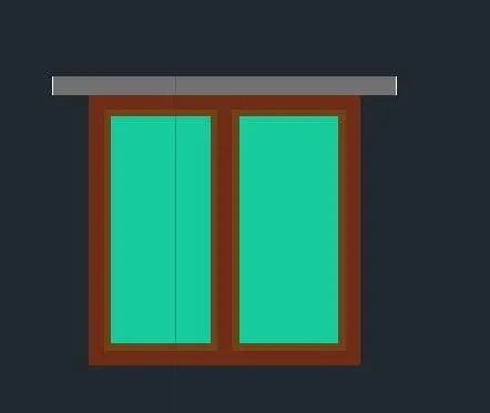
Step 13:Draw the windows
Using boundary option and subtract option
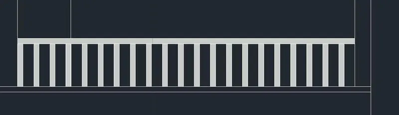
Step 14:Draw the balustrade and handrail
Select the area using region tool
Extrude the area
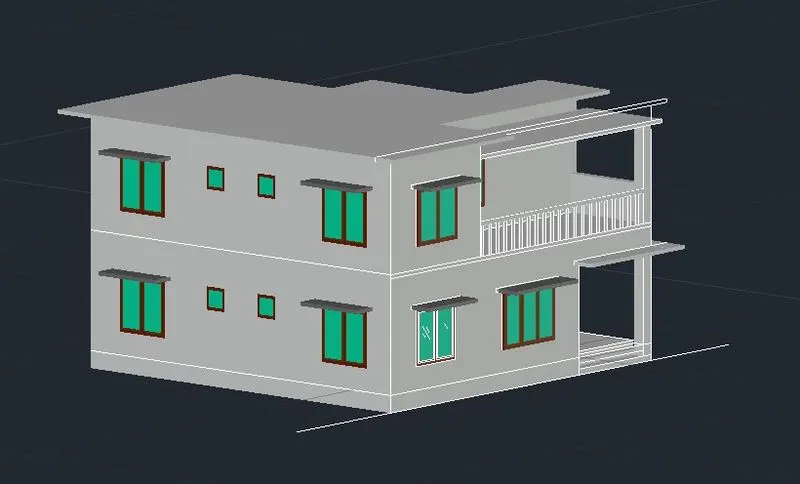
Step 15:Place the windows at correct positions
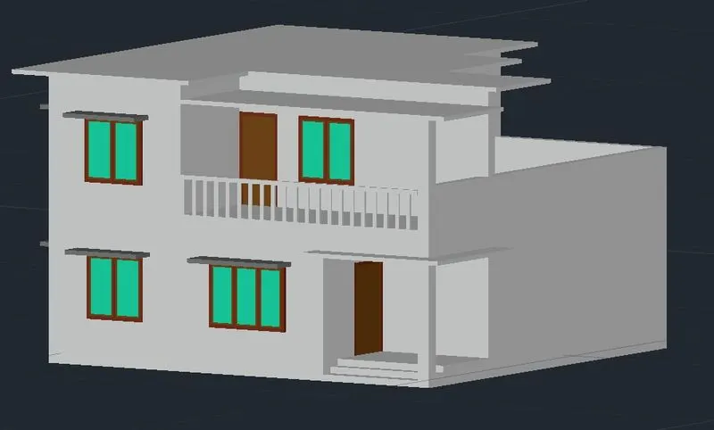
Step 16:Select visualize in ribbon
Select material browser
Select the suitable material
Click on ‘Adds to material document’
Select the element to provide material
Select the material
Right click and select ‘Assign to selection’
Step 17:Set camera using camera option in ribbon
Step 18:Provide environment option in render ‘on’
Step 19:Select ‘render’ option in render settings
Step 20:Save the rendered file
RESULT
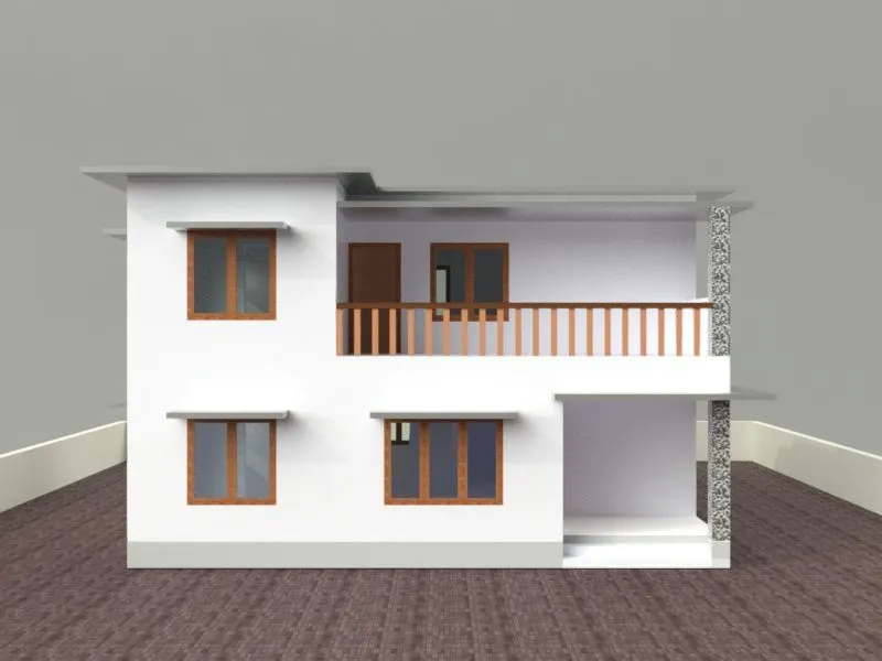
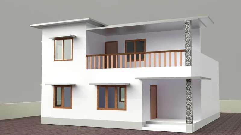
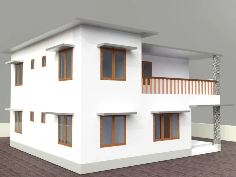
Here we studied in detail to draw a plan and elevation and to draw the isometric view
And to render the the isometric view by providing the materails in the mareial browser