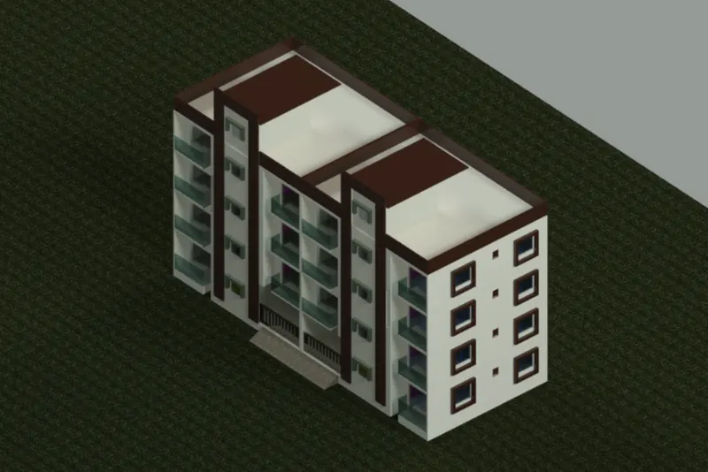
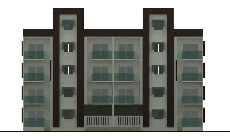
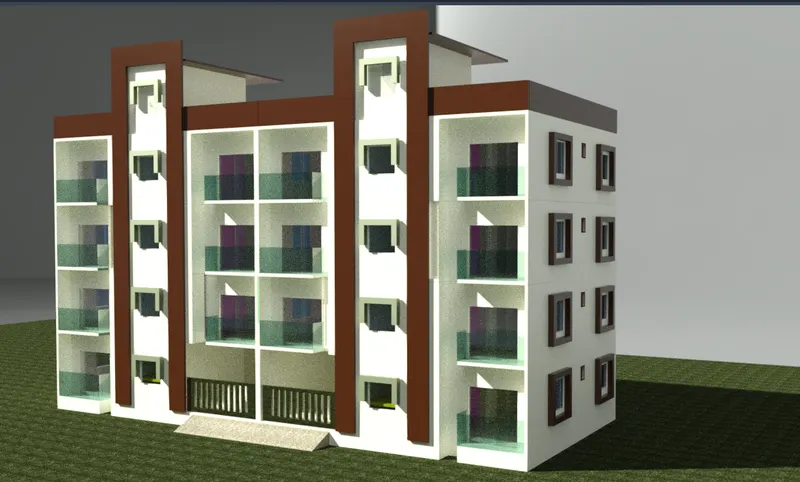
Project 2_Creating a 3D rendered model for a Residential Building in AutoCad
AIM :
Create a 3 dimensional model of the residential building with a rendered view.
INTRODUCTION :
In this project user have created a plan in 2d then user have converted it into 3d using Autocad 3d, applying materials and rendering. user used many 3d commands to know the importnace of it such as subtract, extrude, union, revolve, sweep, etc. we practise on different viewports, providing materials and render the model.
the main objective of this project is to review and refresh almost most of the tools which will be used by professional engineers while drafting a 3d drawing.
in this project, user designed elevation and floor plan for 4 floors building having plot size 40 x 40 sq.ft. we have completed this project in seven steps.
PROCEDURE :
STEP-1: to draw the floor plan in 2d.
- type un and press enter > select architectural > select feet inches > precision 0'0"
- make layers for components like wall, doors, windows, text, etc and assigned them different colours
- using the line, construction line, rectangle, offset, trim, fillet, dimlin draw the ground floor plan and 1,2,3, floor plan.
- draw doors, window, staircase position
- provide suitable style and text using dimstyle command.
- using dimlin command dimensions are provided
- next step is to provide staircase take riser=6" and tread=10"
- the ground floor plan has different dimensions and 1,2,3 rd floor have simliar dimensions
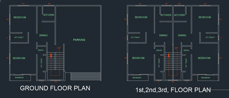
STEP-2 : covert the model into 3d
- used 3d modelling workspace and visual style 2d wireframe
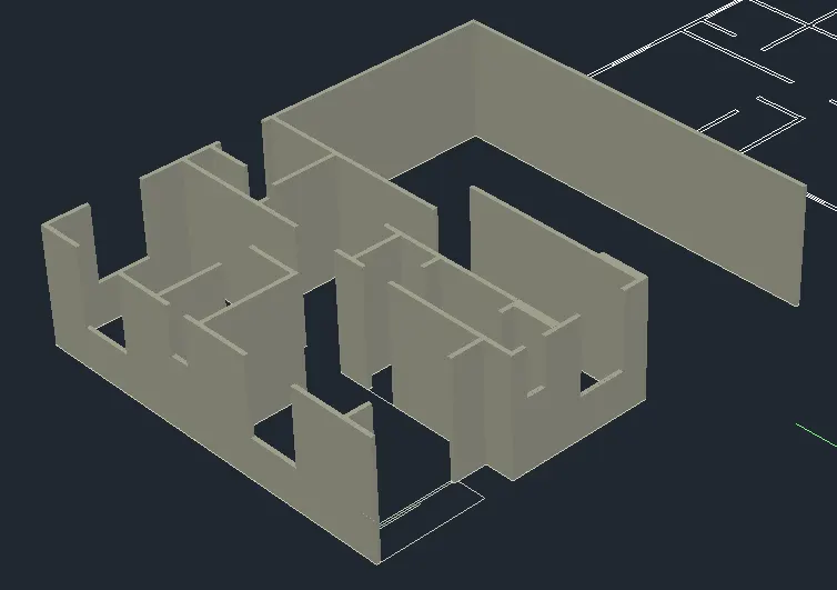
- type boundary > give boundary region to walls
- type extrude select walls and provide extrude height of 10'
 -
-
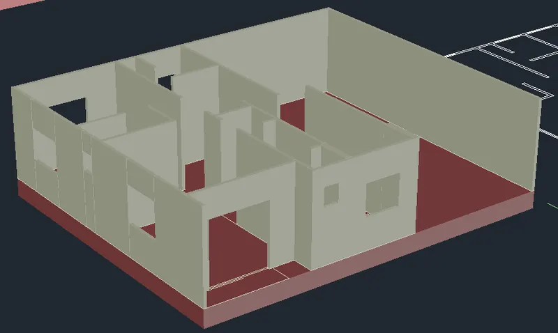
- set the windows size and ventilator size by providing sill height 3.5'
- by using extrude command provide plinth to structure
- height of plinth 2'
STEP-3 : make window, ventilator, sliding door
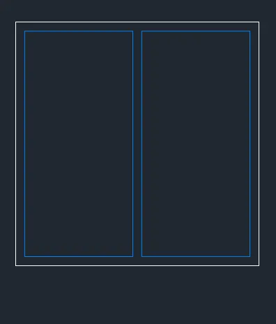
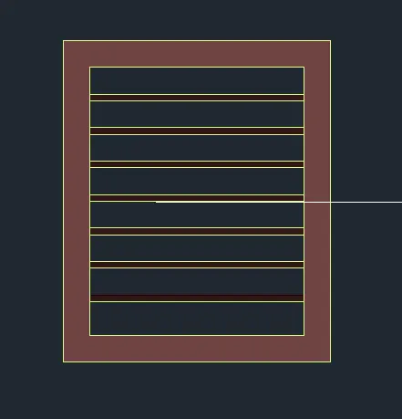
- make window using rectangle command
- provide offset to rec inside
- explode it
- type boundary > provide region boundary
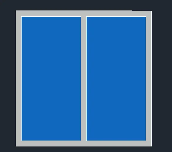
- use extrude to provide thickness to window
- use subtract command to set glass panels
- make ventilator using similar command use in window
- ventilator size 1'8" x 2'
STEP-4 : design staircase
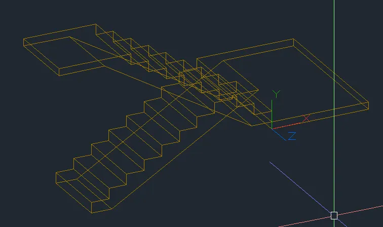
- for staircase set the ucs
- use line command provide riser - 6" and tread- 10"
- make 9 steps using this dimensions
- provide landing
- type boundary > select region > pick point
- select boundary of staircase
- type extrude > select object
- give extrude width of 3'6"
- type union > join the objects
- use simliar procedure and draw the one more stair design above it
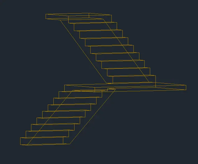
- set the ucs
- select stair layers and assign on object
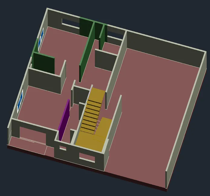
- type move > select object >
- move staircase on plan location and paste it
STEP- 5 : provide roof and sliding door
- type extrude > select sliding door position > extrude it at height of 7 '
- go to material browser and provide glass material to door
- go to top view
- type rectangle as roof of building
- give boundary region to rec
- type extrude and give thickness as 5" as slab thickness
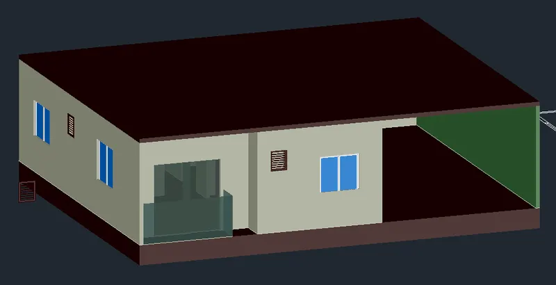
STEP-6 : make 1,2,3rd floor
- copy the 1,2,3rd floor plan on roof of building
- put roof layer off
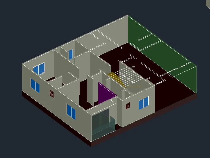
- turn the roof layer on
- select wireframe or hidden visual style
- type extrude > select walls > give height of 10'
- using simliar procedure we followed on ground floor to develop 3d use it here
- windows are in similaar size so just copy the window on above floor
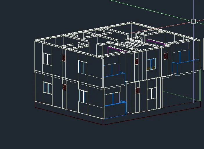
- set ucs
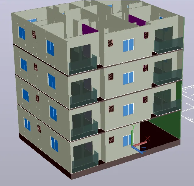
- type copy > select first floor
- copy the floor as 2nd and 3rd floor
- 
STEP-6 : draw elevation finishing components , top roof, parapet, window chajjas
- select top view
- set ucs
- make roof on building using extrude commmand
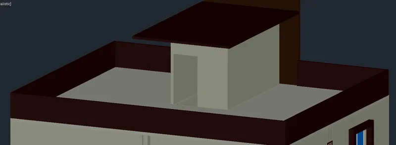
- here we need to subtract area of staircase to make tower
- draw rectangle as staircase area
- using subtrat command subtract the area
- using extrude and rec command draw the tower for staircase
- using rectangle, extrude and region command draw the parapet for bbuilding
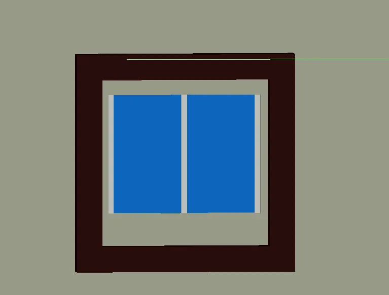
- draw chajja in rectangular pattern sorund the window
- set ucs
- use rectangle , extrude and subtract command to draw this fig
- set ucs
- on front elevation of building
- select hidden visual style
- used rectangle command , line command, extrude , subtract and boundary region command
- draw the elevation components as shown
- for gate use copy array to provide design
- provide the ground to building
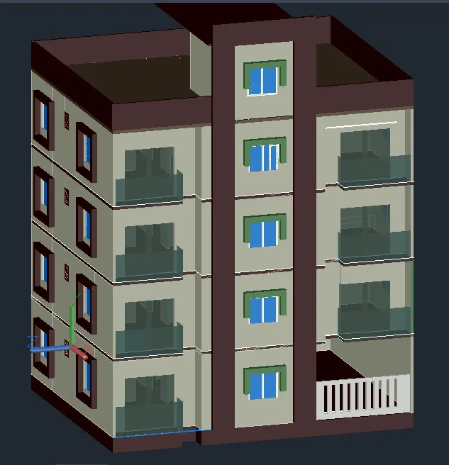
- provide slope roof at bottom of gate as it is parking area entrance
- use pline command
- boundary > select region and pick point
- use extrude and draw the componenets
STEP-7 : Assign material to building
- go to material browser
- select material glass , stone , wall paint etc
- select the object and assign the material
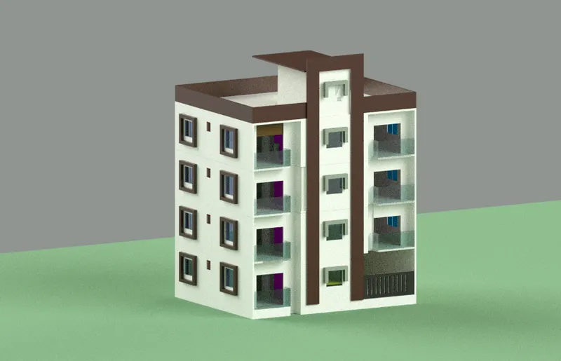
mirror the exist building
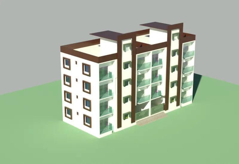
STEP-8 : Rednder the model
- go to visualize > go to render
- manage the environment, sun light , pixel
- render accuracy and quality
- render the fig
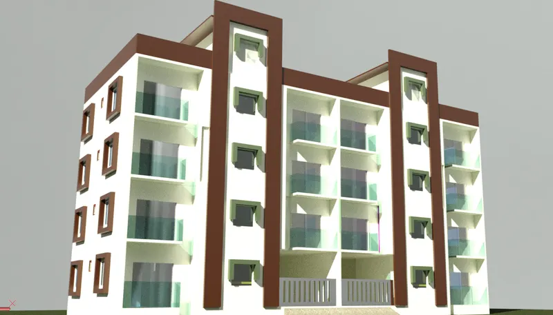
RESULT :
Create a 3 dimensional model of the residential building with a rendered view.