Creating a Floor plan, Footing detail and Isometric view using AutoCad
AIM : creating a floor plan, footing detail and isometric view using autocad.
INTRODUCTION :
this project will help us to introduce various tools in autocad such as drawing rectangle, polylines, move, offsets, copy, rotate, drafting and setting dialog box etc. by using these tools we have created footing details, isometric views, floor plan and we have mentioned detail procedure to draw it.
PROCEDURE :
1. C.S. of load bearing wall over spread footing :
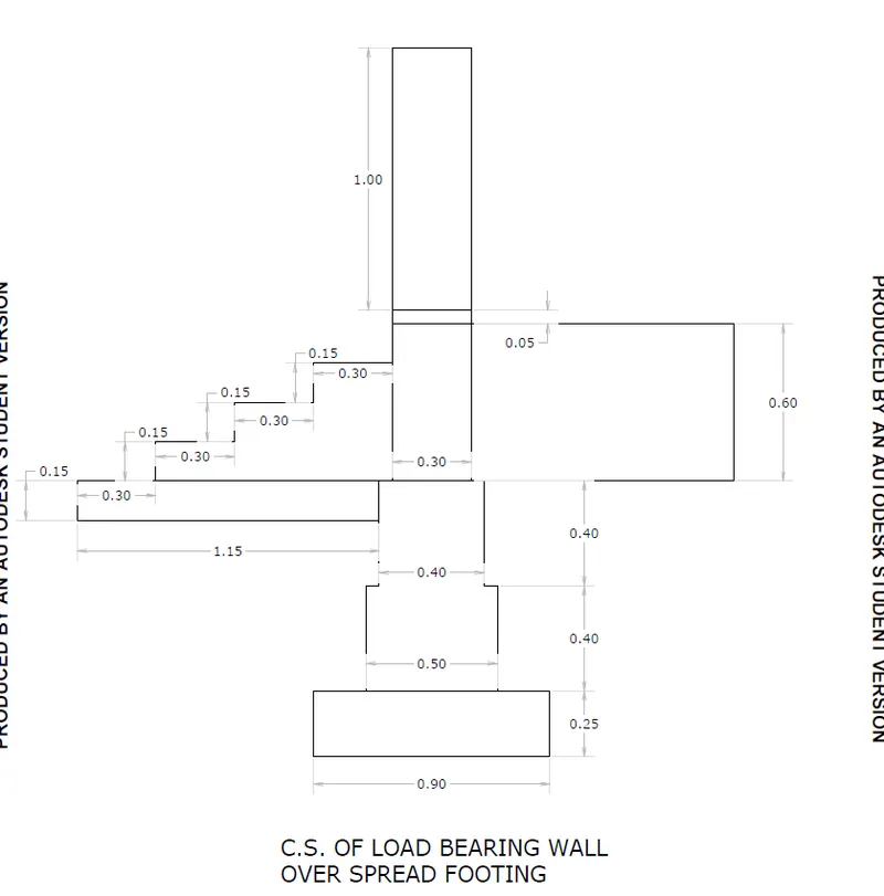
step-1
- type rect for rectangle command and press enter.
- specify first corner point.
- select 'dimension' in command bar.
- specify length of rectangle- 0.90 press enter.
- specify width of rectangle- 0.25 press enter then esc
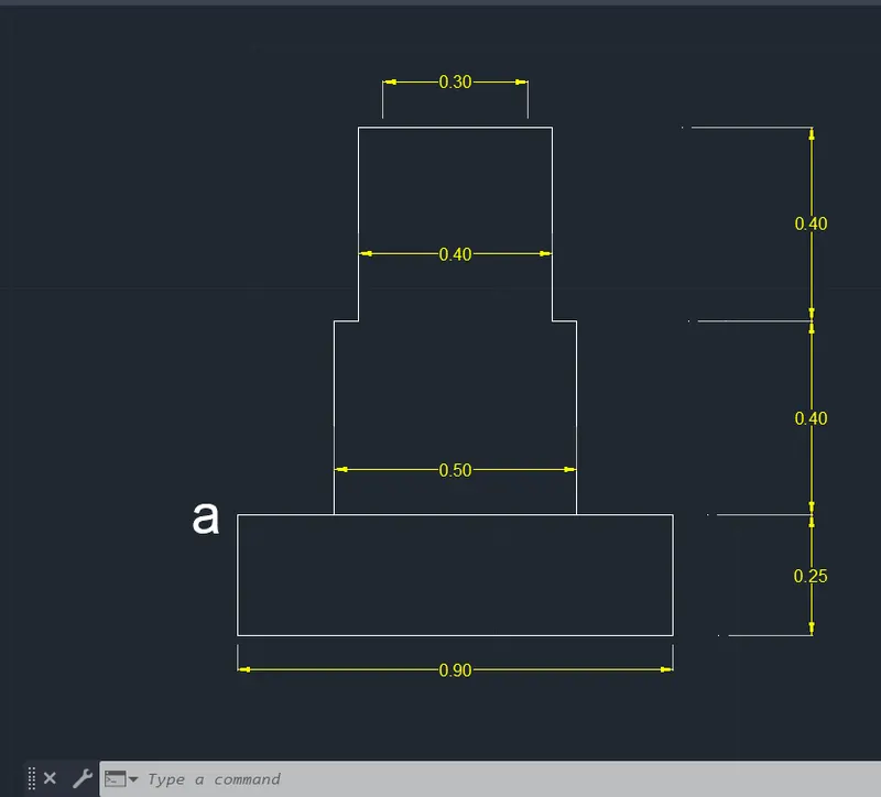
step-2
- type L for selecting line command press enter
- specify the start point 'a'
- specify the next point : @0.20,0 press enter
- specify the next point : @0,0.40 press enter
- specify the next point : @0.20,0 press enter
- specify the next point : @0.05,0 press enter
- specify the next point : @0,0.40 press enter
- specify the next point : @0.30,0 press enter
- specify the next point : @0.05,0 press enter
- specify the next point : @0,-0.40 press enter
- specify the next point : @0.05,0 press enter
- specify the next point : @0,-0.40 press enter and then esc
step-3
type L for selecting line command press enter
- specify the start point 'd'
- specify the next point : @0.05,0 press enter
- specify the next point : @0,0.60 press enter
- specify the next point : @0.30,0 press enter and then esc
step-4
type L for selecting line command press enter
- specify the start point : 'b'
- specify the next point : @0,0.05press enter
- specify the next point : @0,1 press enter
- specify the next point : @0.30,0 press enter
- specify the next point : @0,-1 press enter
- specify the next point : @0,-0.05 press enter
- specify the next point : @0,-0.60 press enter and then esc.
step-5
- type O for offset command press enter
- specify offset distance : 0.05
- select object : selct line bc for offset press enter and then esc.
step-6
- type L for selecting line command press enter
- specify the start point 'd'
- specify the next point : @0,-0.15 press enter
- specify the next point : @-1.15,0 press enter
- specify the next point : @0,0.15 press enter
- specify the next point : @0.30,0press enter
- specify the next point : @0,0.15 press enter
- specify the next point : @0.30,0press enter
- specify the next point : @0,0.15 press enter
- specify the next point : @0.30,0press enter
- specify the next point : @0,0.15 press enter
- specify the next point : @ 0.30,0 press enter and then esc
step-7
- type L for selecting line command press enter
- specify start point 'e'
- specify next point : @1.15,0 press enter and then esc
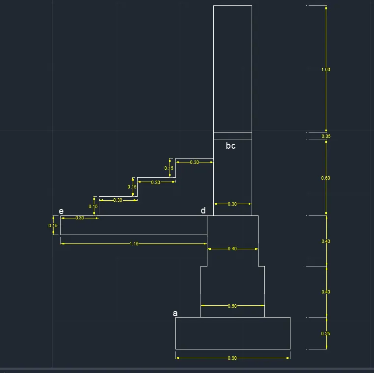
2. C.S of isolated footing :
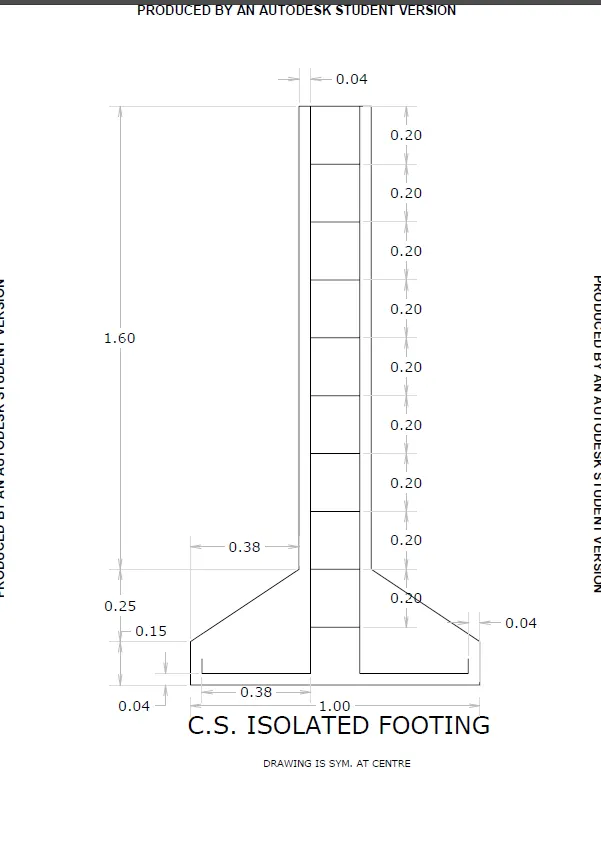
Step-1 :
- type rec for rectangle command
- specify first corner point
- specify dimensions
- specify length of rectangle : 1
- specify width of rectangle : 0.40
step-2 :
- type cha for chamfer command
- select distance option
- specify first chamfer distance : 0.25
- specify second cahmfer distence : 0.38
- select first line
- select second line
- select trim command press enter
- trim line 'ab'
step-3 :
type L for selecting line command press enter
- specify the start point : 'a'
- specify the next point : @0,1.60press enter
- specify the next point : @0.04,0 press enter
- specify the next point : @0,-1.96 press enter
- specify the next point : @-0.38,0press enter
- specify the next point : @0,0.04 press enter and then esc.
step-4 :
type L for selecting line command press enter
- specify the start point : 'b'
- specify the next point : @0,1.60press enter
- specify the next point : @-0.04,0 press enter
- specify the next point : @0,-1.96 press enter
- specify the next point : @0.38,0 press enter
- specify the next point : @0,0.04 press enter and then esc.
step-5 :
- type L for line command
- connect the line 'cd'
- type o for offset command
- specify offset distance : 0.20
- select line 'cd'
- make 9 offset of line cd

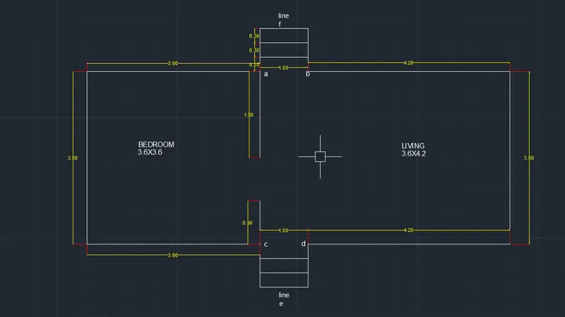
3. line diagram of a two bedroom building :
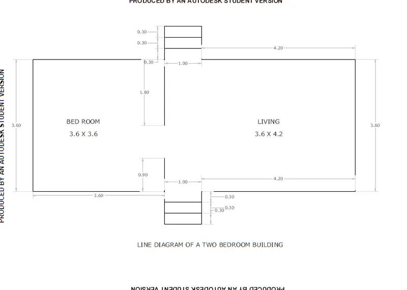
step-1 :
- type L for selecting line command press enter
- specify the start point
- specify the next point : @0, 1.80 press enter
- specify the next point : @-3.60,0 press enter
- specify the next point : @0,-3.60 press enter
- specify the next point : @3.60,0press enter
- specify the next point : @0,0.90 press enter
- specify the next point : @0.30,0press enter
step-2 :
type Line command press enter
select point 'c'
- specify the next point : @0,-0.90 press enter
- specify the next point : @1,0press enter
- specify the next point : @0,-0.90 press enter
step-3 :
- type offset command '0'
- specify offset distance : 0.30 press enter
- select object of offset : line 'e'
- make 2 offset above the line
step-4 :
- type L for selecting line command press enter
- specify the start point 'd'
- specify the next point : @4.20,0 press enter
- specify the next point : @0,3.60 press enter
- specify the next point : @-4.20,0 press enter
- specify the next point : @0,0.90press enter
- specify the next point : @1,0 press enter
- specify the next point : @0,-0.90press enter and press esc
step-3 :
- type offset command '0'
- specify offset distance : 0.30 press enter
- select object of offset : line 'f'
- make 2 offset below the line
- use dimlin command for dimension measurement and dimstyle for dimensions editing.
4. C.S. of load bearing wall showing foundation details :
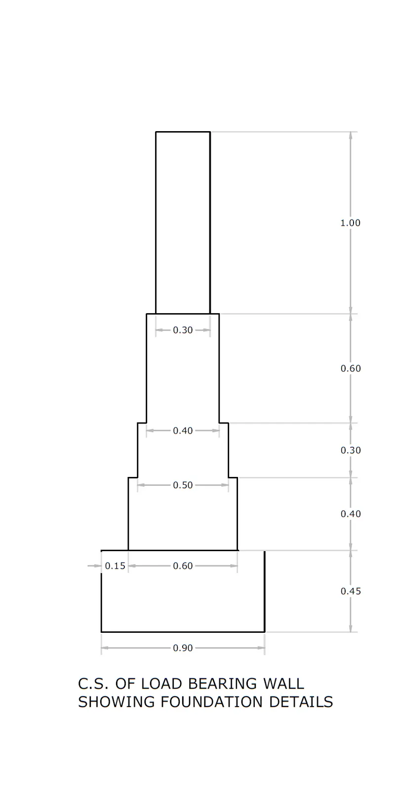
step-1:
- type rect for rectangle command and press enter.
- specify first corner point.
- select 'dimension' in command bar.
- specify length of rectangle- 0.90 press enter.
- specify width of rectangle- 0.45 press enter then esc
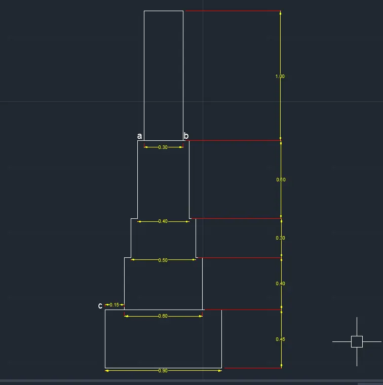
step-2
- type L for selecting line command press enter
- specify the start point 'c'
- specify the next point : @0.15,0 press enter
- specify the next point : @0,0.40 press enter
- specify the next point : @0.05,0 press enter
- specify the next point : @0,0.30press enter
- specify the next point : @0.05,0 press enter
- specify the next point : @0,0.60press enter
specify the next point : @0.05,0 press enter
- specify the next point : @0,1 press enter
- specify the next point : @0.30,0 press enter
- specify the next point : @0,-1press enter
- specify the next point : @0.05,0 press enter
- specify the next point : @0,-0.60press enter
- specify the next point : @0.05,0 press enter
- specify the next point : @0,-0.30press enter
- specify the next point : @0.05,0 press enter
- specify the next point : @0,-0.40press enter and press esc
step-3 :
-type L for line command press enter
- slect point 'a' connect it to point 'b' press enter and then esc.
5. isomteric view of steps :
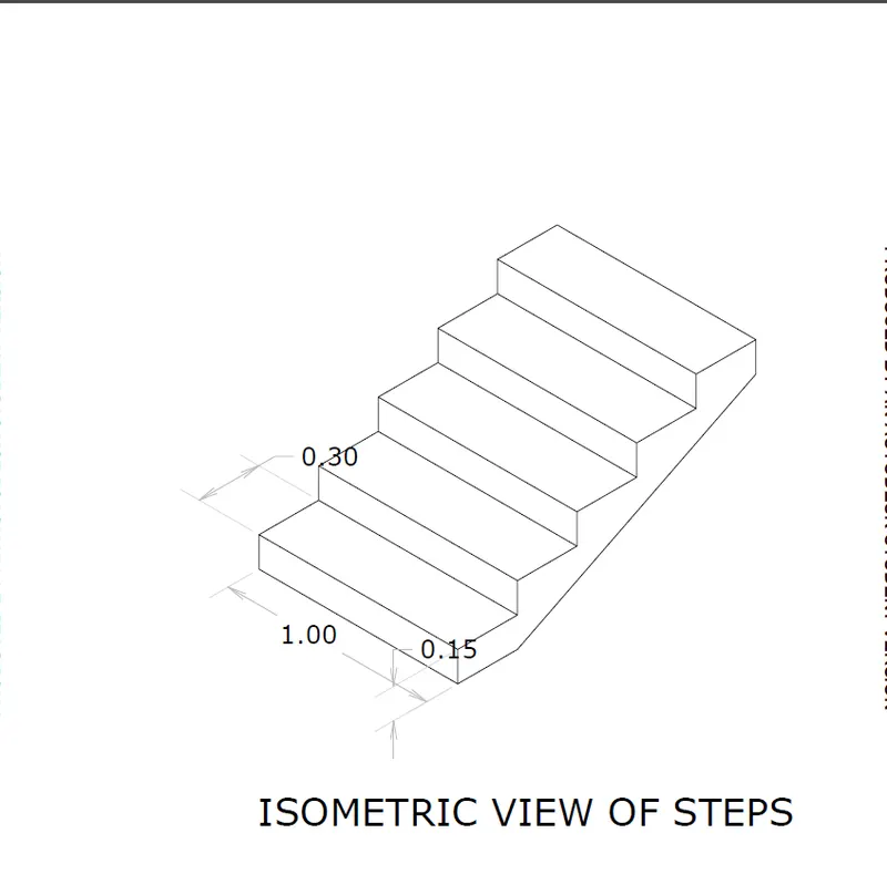
step-1 :
-turn on the isometric drafting
-type DS and enter
- turn off snap and grid in drafting table
- turn on isomteric snap
step-2 :
- select isoplane left by using F5 key on keyboard
- keep ortho mode on
- type L for line command press enter
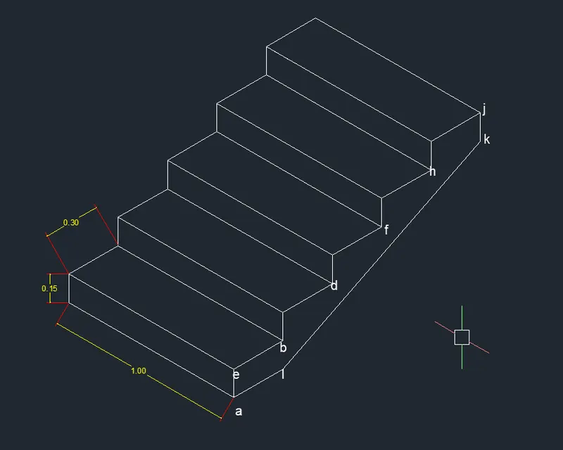
- select pont a move the mouse cursor top (North) type 0.15 press enter
- move the NW direction type 1 press enter
- move the cursor to south type 0.15 press enter
- move the cursor SE direction type 1 press enter and press esc
- type l for line command press enter
- select point 'e' and change the isoplane to top
- move the cursor to NE direction and type 0.30 and press enter
- move the sursor to NW direction and type 1 and press enter
- move the cursor to SE direction and type 0.30 and press enter
- move the sursor to SW direction and type 1 and press enter
step -3 :
- type co for copy press enter
- select the object made by above points and pick it from 'a' point
- paste it on point b,d,f,h,j. press enter and esc
step-4 :
- type L for line command
- make isoplane left
- select point 'j'
- move the cursor to S direction type 0.15 press enter and esc
- type l for line command and change isoplane to top
- move the cursor to NW direction type 0.30 press enter and esc
- type line command and join the point 'i' and 'k' by line and press enter and then esc.
6. isometric view of gable wall :
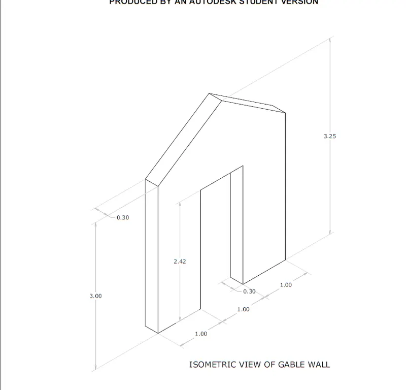
step-1 :
-turn on the isometric drafting
-type DS and enter
- turn off snap and grid in drafting table
- turn on isomteric snap
step-2 :
- select isoplane left by using F5 key on keyboard
- keep ortho mode on
- type L for line command press enter
- select pont 'a' move the mouse cursor top (North) type 3 press enter
- move the NW direction type 0.30 press enter
- move the cursor to south type 3 press enter
- move the cursor SE direction type 0.30 press enter and press esc
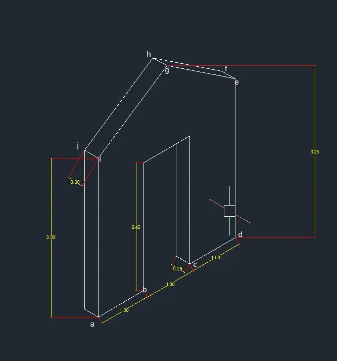
- type L for line command press enter
- select point 'a' and change the isoplane to top
- move the cursor to NE direction and type 1 and press enter
- move the sursor to N direction and type 2.42 and press enter
- move the cursor to NE direction and type 1 and press enter
- move the sursor to S direction and type 2.42 and press enter
- move the sursor to NE direction and type 1 and press enter
- move the cursor to N direction and type 3 and press enter
- move the sursor to NW direction and type 0.30 and press enter
step-3 :
- type L for line command
- select point 'c' and move the cursor to NW type 0.30
- move the cursor to north join to line and trim the extra line press enter and esc.
step-4 :
- for g point we have to take reference line
- type L command for line
- select point 'a' move the cursor to NW and type 1.5 press enter
- move cursor to N and type 4 press enter and then esc.
- type l for line command
- select point 'g' move cursor to NW type 0.30 press enter
- similarly for point 'i'
- finally join the line from 'f' to 'h' and 'h' to 'i' by keeping ortho mode off.
RESULT :
hence we sketched following drawings in autocad as per dimensions given and using various tools,
- C.S. of load bearing wall over spread footing
- C.S. of isolated footing
- line diagram of a two bedroom building
- C.S. of load bearing wall showing foundation details
- isometric view of steps
- isometric view of gable wall.