Drafting of various geometries using Chamfer, Fillet tool in AutoCad
AIM : drafting of various geometries using chamfer, fillet tool in autocad.
INTRODUCTION :
in this project we will work on different sketches provided. for this sketches we have used different types of units such as decimal, architecttural, engineering etc. we are going to use different tools like chamfer, fillet, mirror, offset, copy, trim, polygon, circle etc. we have provided dwtails procedure to draw this sketches.
PROCEDURE :
1.
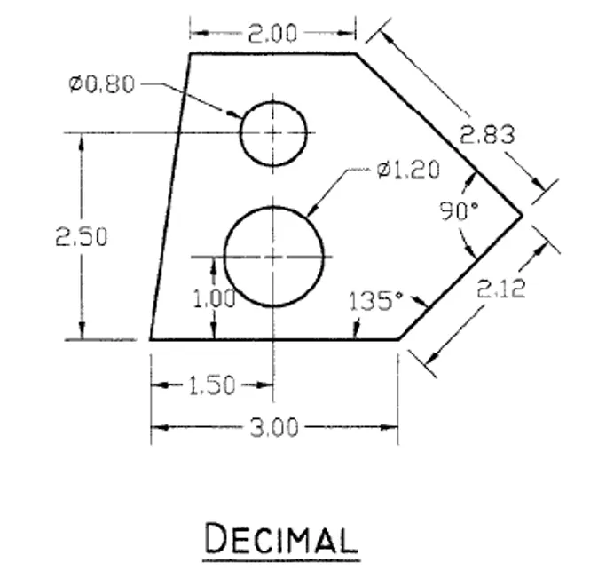
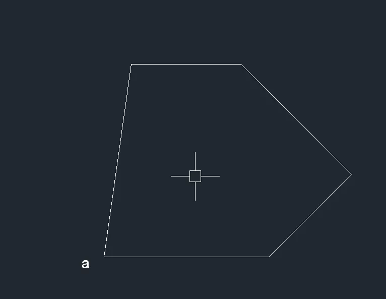
step-1 :
- type L command for line press enter
- select to point 'a'
- specify next point : 3 press enter
- now type 'OSNAP' for object snap, turn on polar tracking and set polar angle setting to 45
- specify next point : 2.12 press enter
- set the angle to 135 degree
- specify next point : 2.83 press enter
- move the cursor to west direction
- specify next point : 2 press enter
- now keep ortho mode off and join the line to point 'a' press enter and then esc.
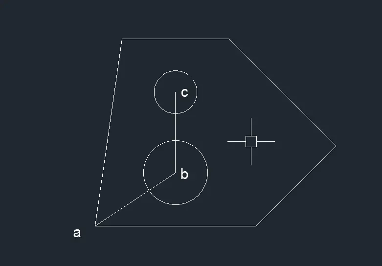
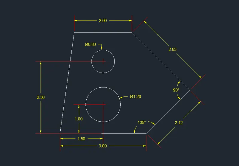
step-2 :
to draw circle, we need to take reference for centre of a circle i.e line from a to b.
- type line command
- select point 'a'
- specify next point : @ 1.5,1 press enter and then esc
- we got b point
- type circle command
- specify centre point for circle : select point b
- select diameter
- specify dimeter for circle : 1.20 press enter
now extend the line from point b to c keeping ortho mode on.
- type circle command
- specify centre point for circle : select point c
- specify diameter for circle : 0.80 press enter
- erase the reference line ab and bc
2.
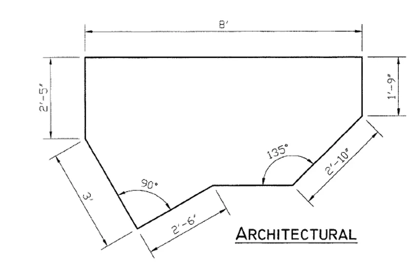
step-1 :
- type UN command for drawing unit
- set length type to architectural, precision 0'0" press on ok.
step-2 :
- type L command for line
- specify first point : select on point 'a'
- specify next point : @2'6"<30 press enter and then esc
- type L for line command
- specify first point : select point 'a'
- specify next point : 3'<120 press enter
- move cursor to north direction
- specify next point : 2'5" press enter
- move cursor to east direction
- specify next point : 8' press enter
- move cursor to south direction
- specify next point : 1'9" press enter
- specify next point : @2'10"<225
- join the line to point 'b'
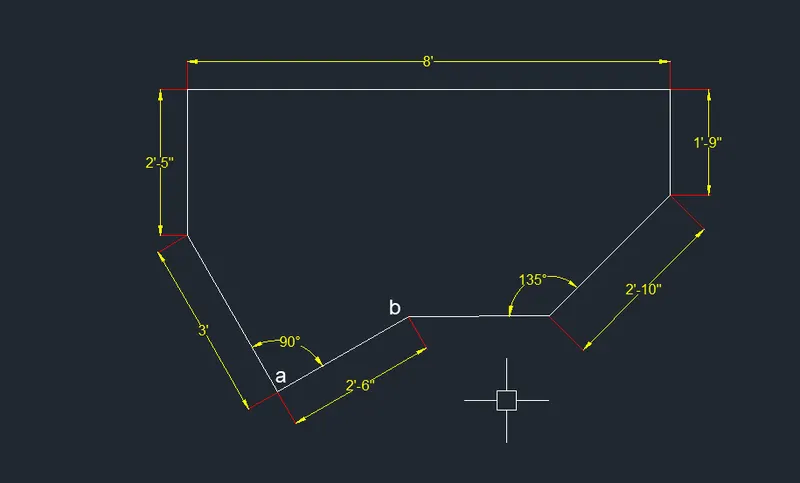
3.
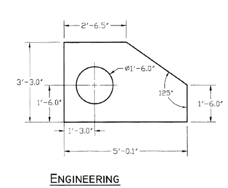
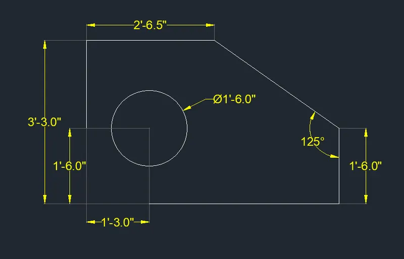
step-1 :
- type UN for drawing unit
- select length type to engineering
- select precision 0'0.0" press on ok.
step-2 :
- type L for line command
- specify first point : select point 'a'
- specify next point : @0,-1'6.0"
- specify next point : @ -5'0.1",0
- specify next point : @ 0,3'3.0"
- specify next point : @ 2'6.5",0
- joint the line to point 'a' press enter and then esc.
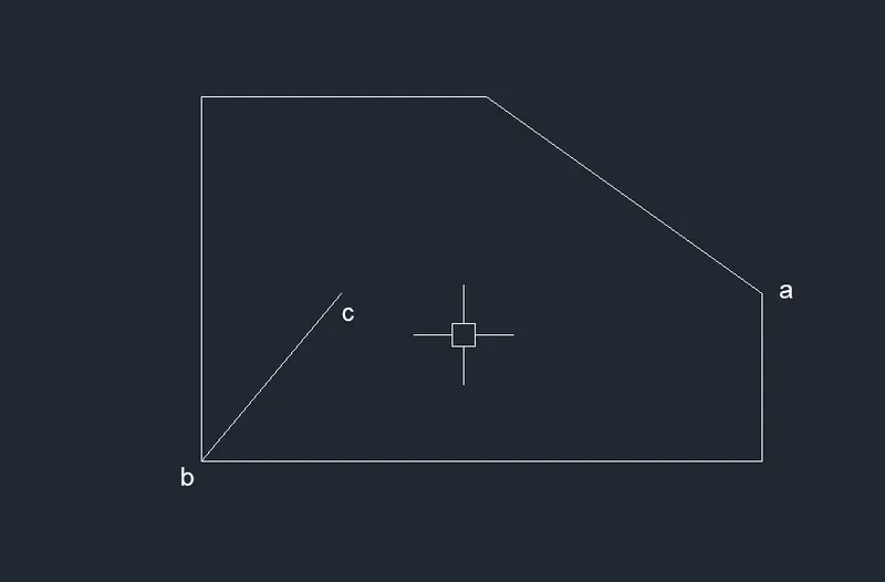
step-3 :
- type L for line command
- specify first point : select point 'b'
- specify next point : @1'3.0",1'6.0" press enter and then esc
- type C for circle command
- specify centre point of circle : select point 'c'
- specify diameter of circle : 1'6.0" press enter and then esc
- erase the reference line bc.
4.
step-1 :
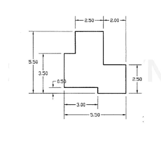
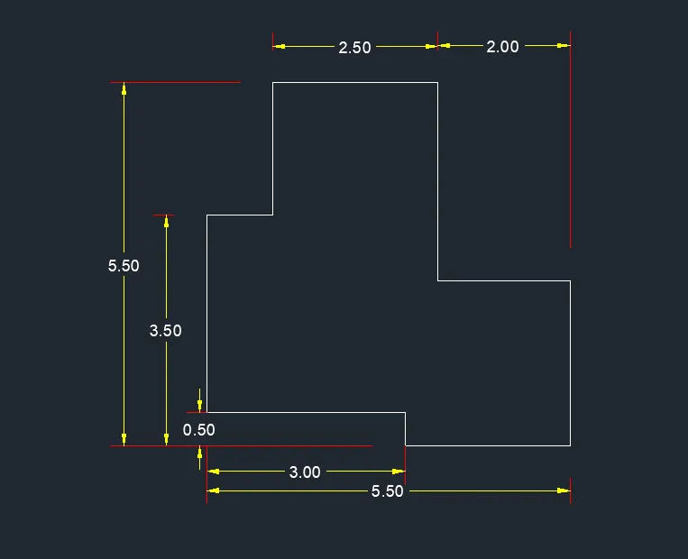
- type UN for drawing unit
- select length type to decimal
- select precision 0.00 press ok.
step-2 :
- type L for line command
- specify first point
- specify next point : @-3,0
- specify next point : @0,3
- speicfy next point : @1,0
- specify next point : @0,2
- specify next point : @ 2.50,0
- specify next point : @ 0,-3
- specify next point : @2,0
- specify next point : @0,-2.50
- specify next point : @-2.50,0
- specify next point : @0,0.50 press enter and then esc
5.
step-1 :
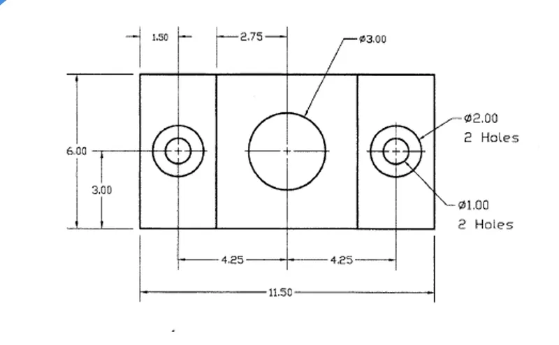
- type L for line command
- specify first point : select point 'a'
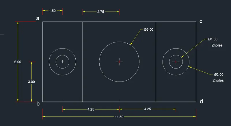
- specify next point :@0,6
- specify next point : @11.50,0
- specify next point : @0,-6
- specify next point : @-11.50,0
step-2 :
- type O for offset command
- specify offset distance : 3 press enter
- select object : select line ab
- repeat the procedure for line c apply offset distance 3
step-3 :
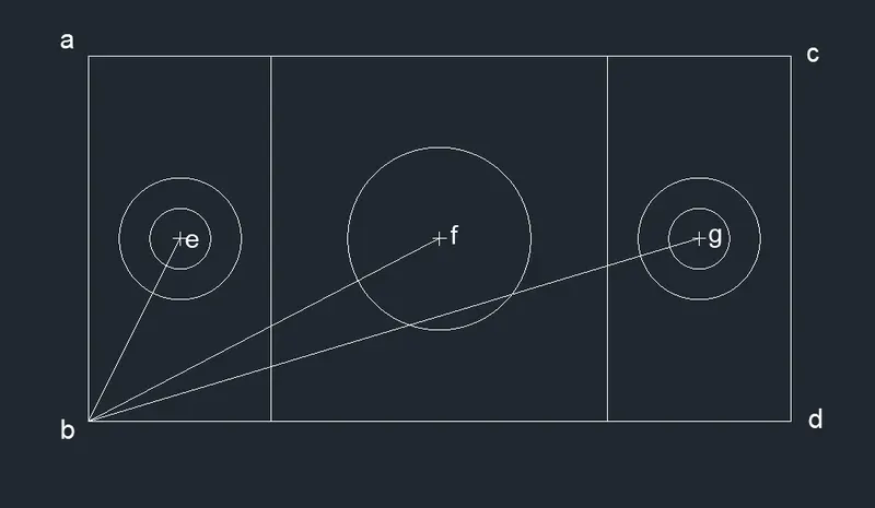
take refrence line for getting centre of circle i.e (e, f, g)
- type L for line command
- specify first point : select point a
- specify next point : @ 1.5,3 pree enter and then esc
- type line command
- specify first point : select point a
- specify next point : @5.75,3 press enter and then esc
- type line command
- speicfy first point : slect point a
- specify next point : @10,3 press enter and then esc
- erase the line be,bf,bg by .
6.
step-1 :
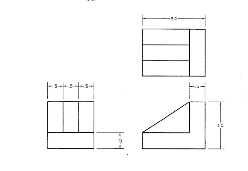
- type rec for rectangle
- specify first corner point : select point b
- select dimension
- specify length of rectangle : 1.5
- specify width of rectangle : 0.5 press enter and then esc.
step-2 :
- type L for line command
- specify first point : select point b
- specify next point : @0,1
- specify next point : @-1.5,0
- specify next point : @0,-1 press enter and then esc
step- 3:
- type O for offset command
- select offset distance : 0.5
- select offset object : select line ab
- make two offset of it.
step-4 :
- type copy command
- copy the given diagram
- type rotate command
- rotate the diagram to 90 degree to west direction
step-5 :
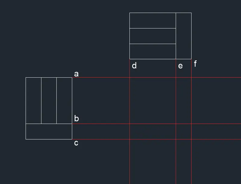
- type ray command for construction line
- select point c, b, a, d, e, f one by one and make construction line
- in diagram it is shown in red colour lines.
step-6 :
- type for L for line command
- specify first point : select point j
- specify next point : @0,1.5
- join the two point g and h by line
- join the two point g and i by line
- similarly join the line gi, il, lk, kj.
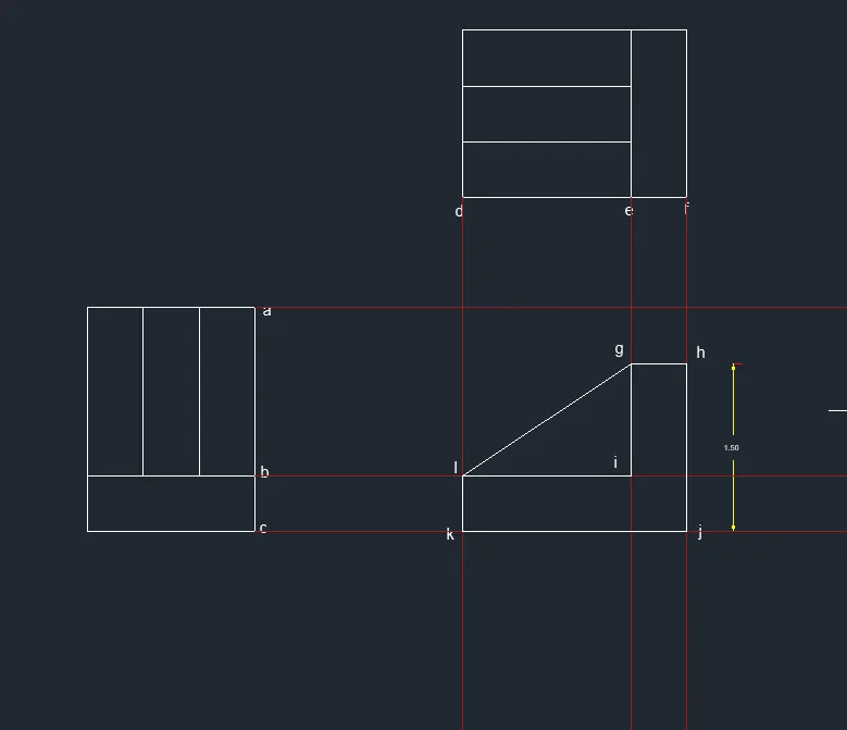
step-7 :
- erase all the construction line for final diagram.
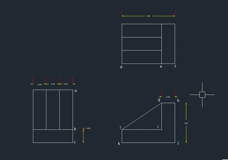
7.
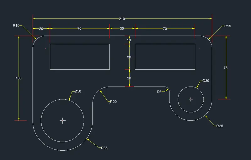
step-1 :
- type L for line command
- specify first point : select point a
- specify next point : @0,100
- specify next point : @210,0
- specify next point : @0,-75
- specify next point : @-25,0
- specify next point : @-90,0
- type L for line command
- specify first point : select point a
- specify next point : @0,-35
- specify next point : @35,0
- specify next point : @0,75 press enter and then esc
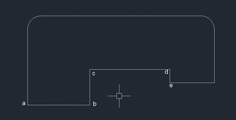
step-2 :
- type fillet command
- select radius
- specify fillet radius : 35
- select first object : select line a
- selecr second object : select line b press enter and then esc.
- follow similar procedure for all the corner which required fillet
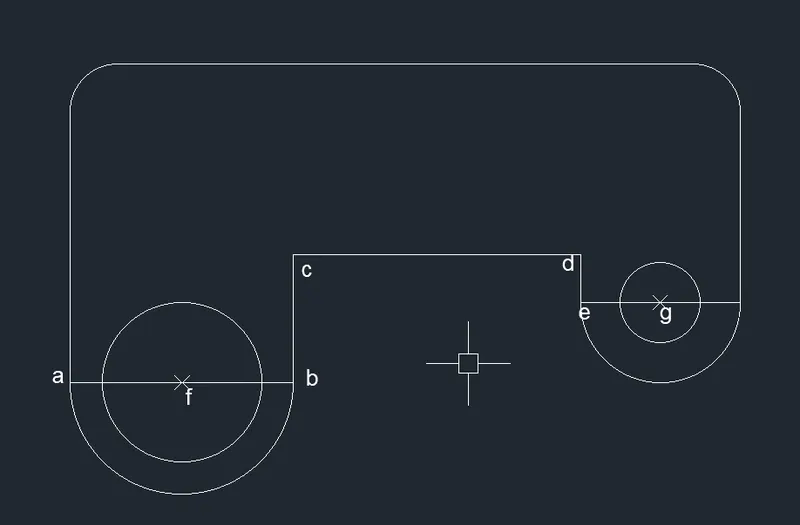
step-3 :
- type C for circle command
- specify center point : select point f
(to get f point set the object snap and move cursor properly it will give the centre)
- select diameter
- specify diameter for circle : 25 press enter and then esc
- do similar procedure for point g and type diameter 30.
step-4 :
- type L for line command
- specify first point : select point a
- specify next point : @20,60 press enter and then esc.
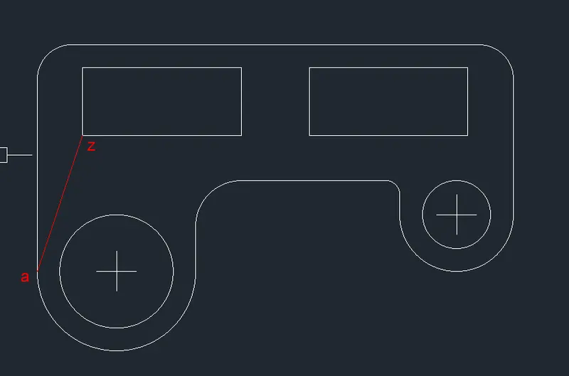
step-5 :
- type rec for rectangle command
- specify first corner point : select point z
- select dimension in command bar
- specify length of rectangle : 70
- specify width of rectangle : 30 press enter and then esc.
- type C command for copy
- select rectangle, keep ortho on
- specify base point : select rectangle from point z
- select displacement mode
- specify displacement : 100 press enter and esc
- erasr reference line az.
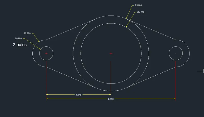
8.
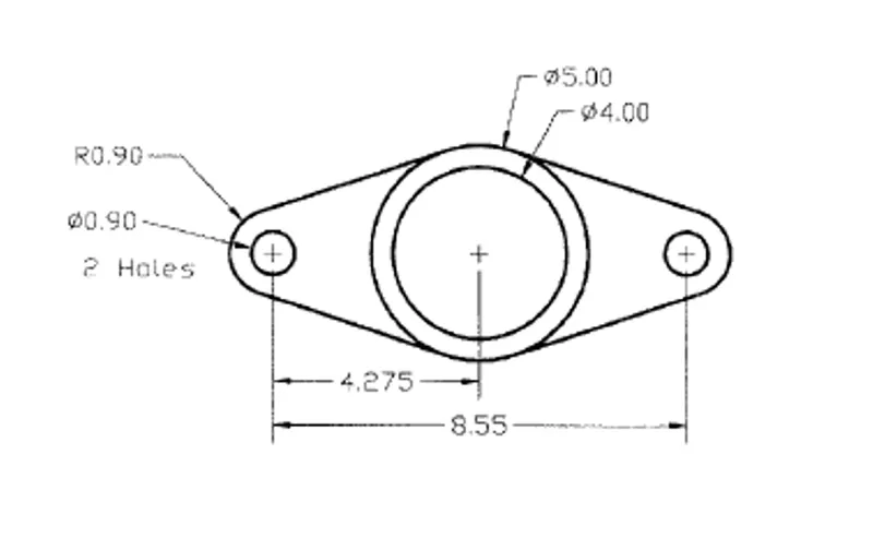
step-1
- type L command for line
- make horozontal line of dimension 8.55
- type C command for circle
- specify centre point : select mid point of line by using object snap
- specify diameter of circle : 4 enter
- repeat the same procedure and specify diameter of circle 5 press enter
- again repeat the procedure taking centre point a and e
- specify diameter of circle 0.90 for both point a and e
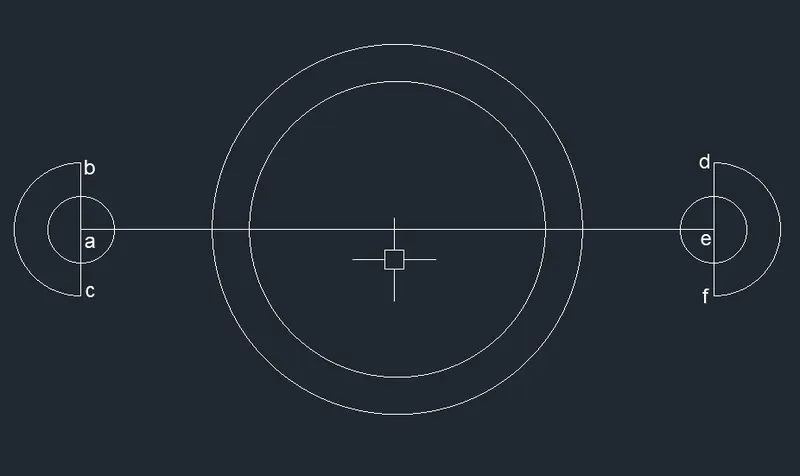
step-2 :
- make reference line i.e line bac and line def for arc for both centre point a and e
- select arc command center end radius
- specify start point : select point b
- specify end point : select point c
- specify radius : 0.90 press enter
- similar procedure for centre point e.
step-3 :
- type OSNAP for drafting setting keep tangent on.
- type L command for line
- select point b and move the cursor towards other circle you will get tangent point click on it
- similar procedure for oher side circle.
- finally erase all reference line.
9.
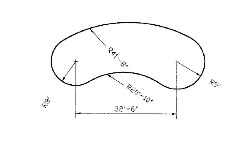
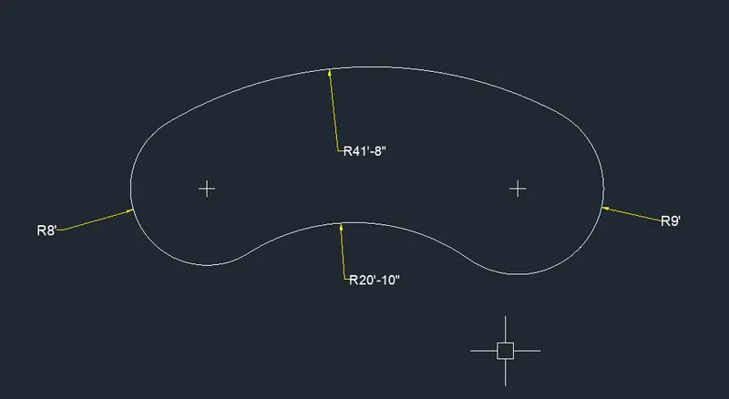
step-1 :
- type L command for line
- make a line of distance 32'6"
- draw a circle at the end of line
- at the left side end draw a circle of radius 8'
- at right side end draw a circle of radius 9'
- type C command for circle
- select tan tan radius
- specify point on object : select the top faces of right circle
- soecify point on object : select the top face of left circle
- specify radius : 41'8"
- repeat the same for bottom arc type radius 20'10"
- erase the reference line.
10.
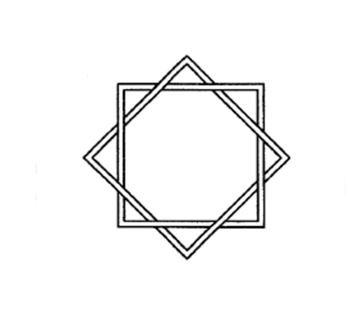
step-1 :
- type rec command for rectangle
- specify first corner point
- select dimnesions
- specify length of rectangle : 5"
- specify width of rectangle : 5"
- type co for copy
- copy the rectangle
- type rotate command
- select object press enter
- rotation angle 45 degree to horizontal
step-2
- type move command
- select object : select copied rectangle and cursor on centre of rec
- move the selected cursor to centre of original rectangle
- type trim
- trim the line as shown in given diagram

11.
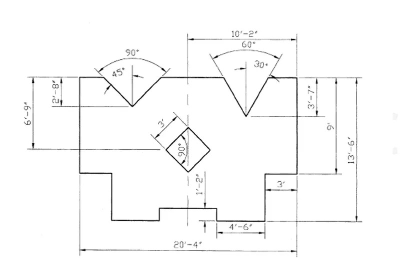
step-1 :
- type L command for line
- specify first point : select any point
- specify next point : @0,-1'2"
- specify next point : @4'6",0
- specify next point : @0,4'6"
- specify next point : @3,0
- specify next point : @0,9
- specify next point : @-3,0
- specify next point : @4'2"<240
- specify next point : @4'2"<120
- specify next point : @ -2'12',0
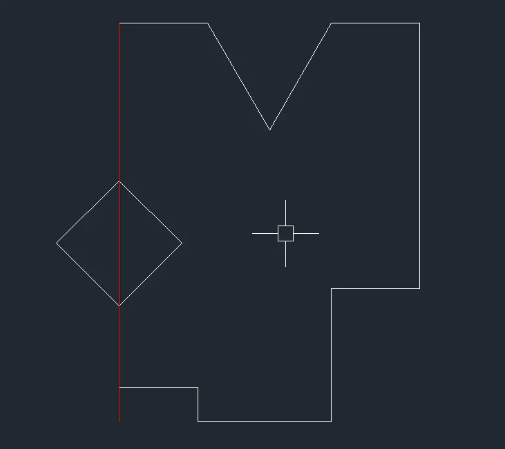
step-2 :
- type L command for line
- take reference line which is shown in above figure in red line.
make a rectangle separately and paste it on red line at distanc 6'9" point from top
- type rectangle command
- specify first corner point
- select dimensions
- specify length of rectangle : 3'
- specify width of rectangle : 3'
- rotate at 45degree.
- select the rectangle from centre point
- and paste it on refrence point which has bottom end point at 6'9" from top
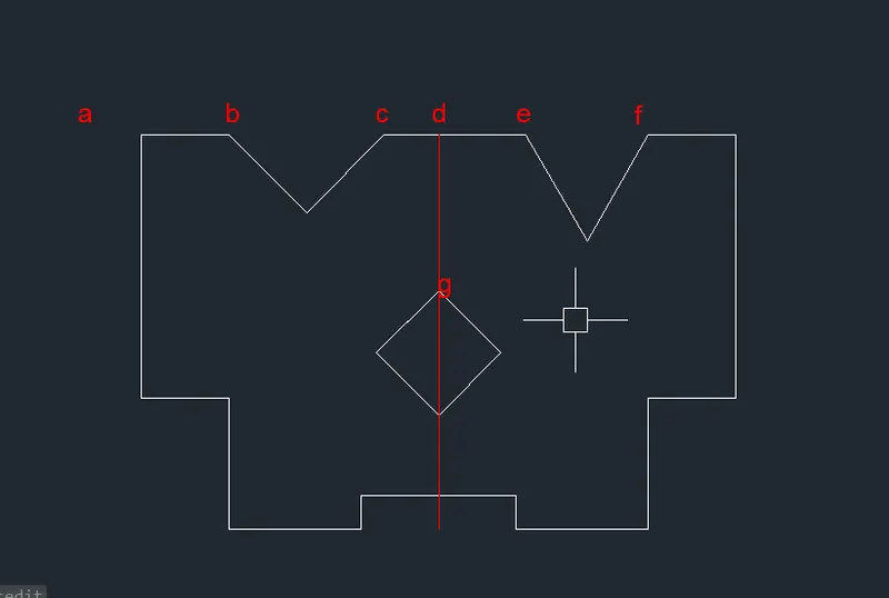
step-3 :
- type mirror command
- select the whole diagram what we get
- and mirror it from point d
step-4 :
erase the bc triangle
- type L command for line
- specify first point : select b point
- speicfy next point : @3'9"<315
- specify next point : @3'9"<45
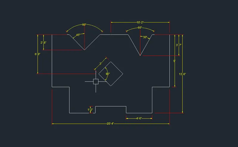
RESULT :
- 1.diagram sketched by using decimal unit.
- 2.diagram sketched by using architectural unit.
- 3.diagram sketched by using engineering unit
- thus we sketched all the drawing using proper unit which has given.