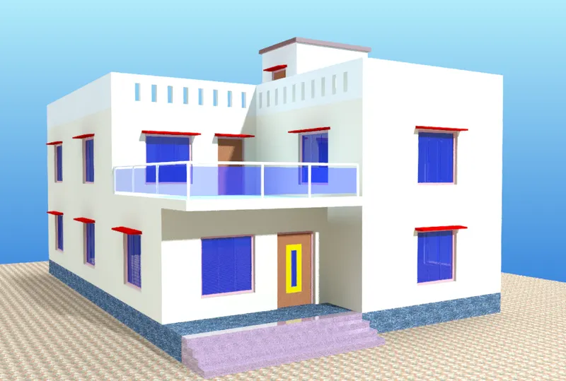
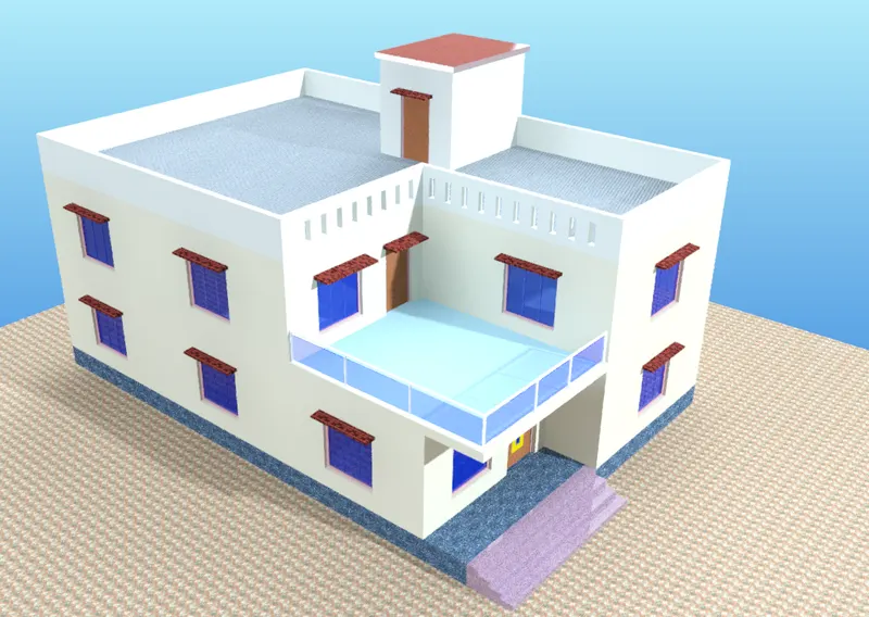
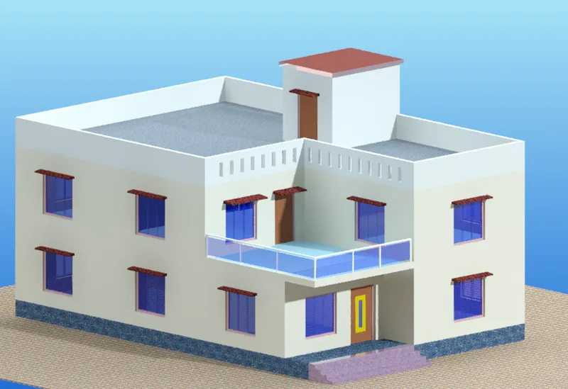
Project 2_Creating a 3D rendered model for a Residential Building in AutoCad
Project 2_Creating a 3D rendered model for a Residential Building in AutoCad.
Create a 3 dimensional model of the residential building with a rendered view.
Aim:
To create the 3D rendered model for a Residential Building in AutoCAD.
Introduction:
The 3D view of a wall spread footing is created in AutoCAD in 3D Modelling workspace using primarily the line and Extrude tools. The procedure of drawing is explained in detail with diagrams of each step and the final result is given.
Procedure:
STEP 1
- Go to START MENU, select AutoCAD 2022 In the Command line type in: STARTUP (ENTER]
- Enter new value of startup: 1
- Go to Application Menu and select New
- Select Metric, click OK
- Enter UNITS command in the command tab
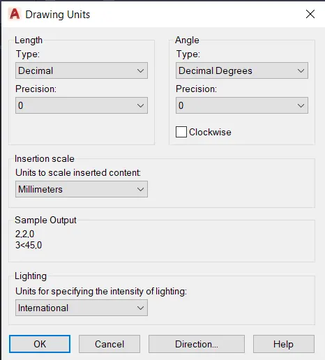
- In the Drawing Units dialog box, select Deciami in Type: 0 In Precision; and Millimeters in Insertion scale.
- Click on OK
- Select 3D Modelling from the Workspace Switching drop down list.
- Set the limits by entering LIMITS in the Command tab. The lower-left corner is specified as 0,0, and the upper
- right corner is specified as 30000,30000.
- visual style >2D wireframe.
STEP 2
- Select the Top view.
- Draw the floor plan of the building using mainly the Rectangle, Line, Offset, Copy and Trim tools.
- Provide dimensions to the drawings.
- Add text where required.
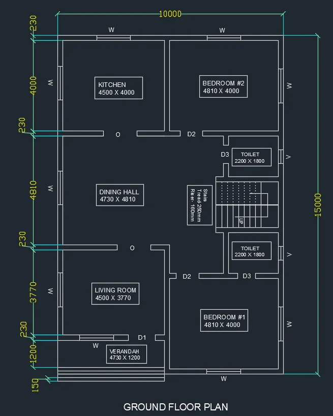
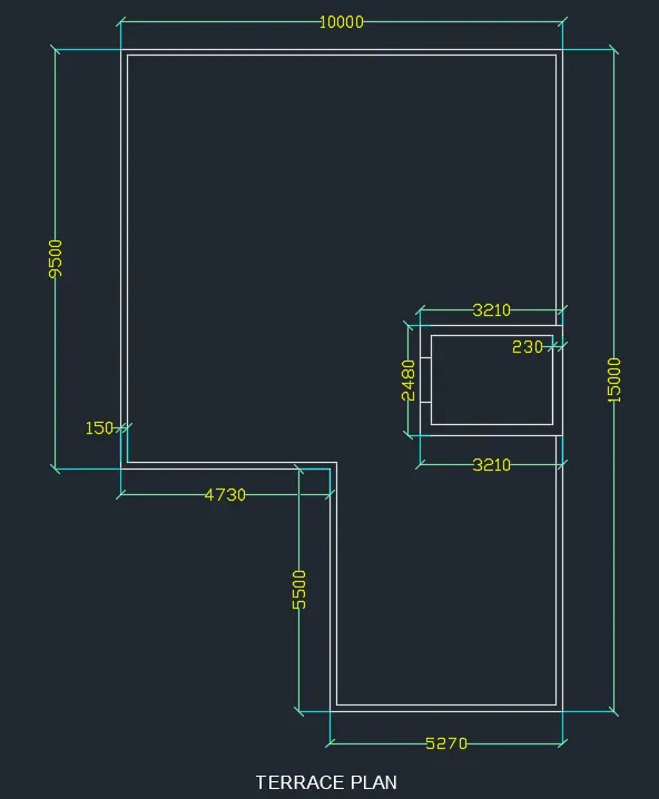
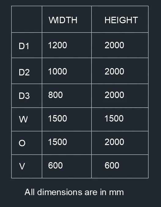
- Create a table containing dimensions of the doors, window, openings and ventilators.
STEP 2
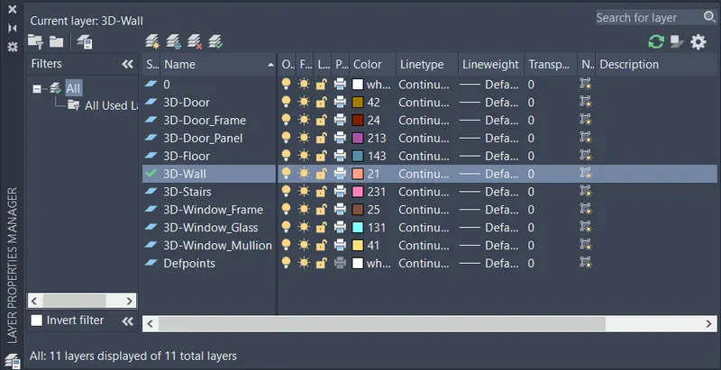
- Click on Layer Properties in the Layer panel on the Ribbon.
- Click on 'New Layer' to create the following layers- 3D Wall, door, stairs, window and floor layers.
- Specify different colors for the different layers and then close the Layer Properties Manager dialog box.
STEP 3
- Select SW Isometric View.
- Set current the 3D-Wall Layer.
- Change viewstyle to Shaded.
- Enter BOUNDARY command in the command tab.
- Specify Object type as Region and Click on Pick points icon in the Boundary Creation Dialog box.
- Click inside the wall portions of the plan.
- Press Enter.
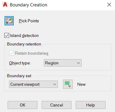
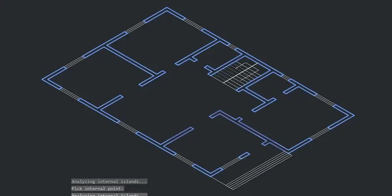
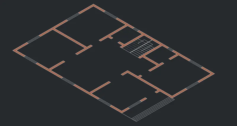
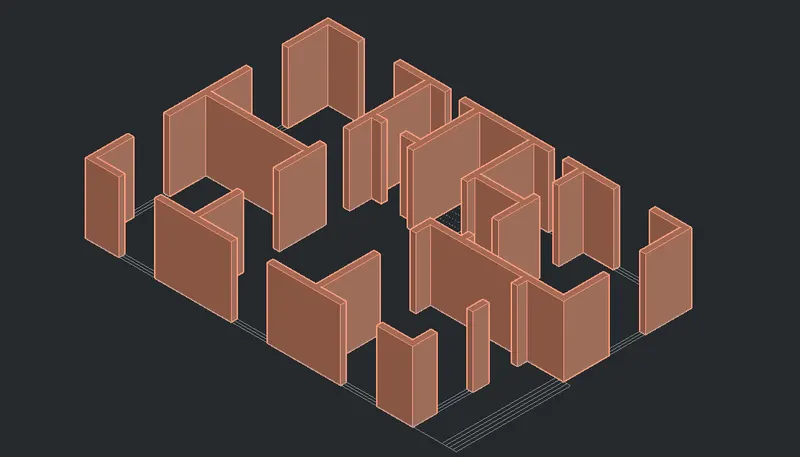
- Enter EXT in the command line to select the Extrude tool.
- Select the boundaries created earlier.
- Press Enter.
- Extrude it to a height of 2870.
STEP 4
- Select the Rectangle tool by entering 'REC' command in the command tab.
- Specify the first corner point as any corner point of the window.
- Specify the other corner as the opposite corner of the window.
- Select the Extrude tool from the Ribbon.
- Extrude the rectangle to a height of 500.
- Again select the Rectangle tool by entering 'REC' command in the command tab.
- Specify the first corner point as any corner point of the window opening at the top of the wall.
- Specify the other corner as the opposite corner of the window.
- Select the Extrude tool from the Ribbon.
- Extrude the rectangle to a height of 870 downwards (Storey height is taken as 2870 mm).
- Similarly all the door and window openings are created using the Rectangle and Extrude tools.
- Use the Union tool the 3D solids to create the below figure.
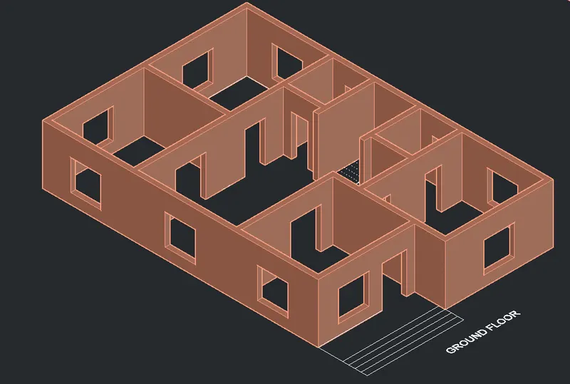
STEP 5
Following the same procedure as Step 4 the first floor walls with openings are created.
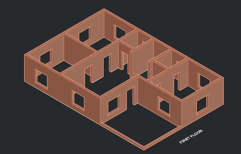
STEP 6
- To create the window, Select the Rectangle tool by entering REC command in the command tab.
- Specify the first point.
- Specify dimension as @1500,1500.
- Select the Offset tool by entering O command in the command tab.
- Specify offset distance of 60.
- Select and offset the previous rectangle.
- Explode the last created rectangle.
- Select the Offset tool by entering 'O' command in the command tab.
- Specify offset distance of 30.
- Select and offset the previous rectangle to create the mullion.
- Press Esc.
- Trim the unwanted portion of lines.
- Set current the 3D window frame layer.
- Enter BOUNDARY command in the command tab.
- Specify Object type as Region and Click on Pick points icon in the Boundary Creation Dialog box.
- Click inside the frame of the window.
- Press Enter.
- Select the Subtract tool, and subtract the mullion and glass portion of the window.
- Repeat the Boundary and Subtract commands to create the million and glass of the window.
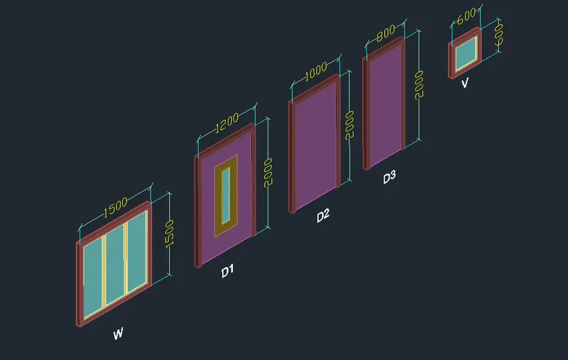
- similarly create door D1,D2,D3 and ventilator V.
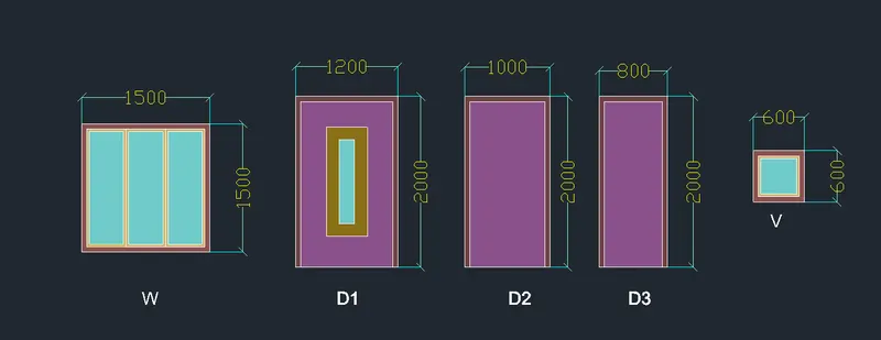
- Enter EXT in the command line to select the Extrude tool.
- Select the window frame boundary,
- Press Enter.
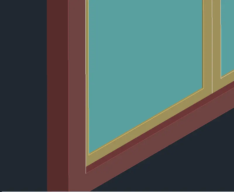
- Extrude it to a height of 75.
- Similarly Extrude the mullion to a height of 30 and the glass to a height of 15.
- Then Move the mullion and glass solids inside to give a depth to the assembly as shown in the below figure.
- Repeat the same process for the all the doors and ventilator assembly.
STEP 7
- Set current the 3D-Stairs layer.
- Adjust the UCS to get the desired side view of the flight of stairs..
- Select the Line tool by entering LINE command in the command tab
- Draw stairs having rise of 160 and tread of 250.
- Press Esc.
- Select the Copy tool by entering 'Co' command in the command tab
- Copy the stairs 8 times to create the flight of stairs.
- Press Esc
- Select the Line tool by entering LINE command in the command tab.
- Draw the landing slab of width 750 and thickness 150.
- Press Esc.
- Select the Line tool by entering LINE command in the command tab
- Draw the waist slab of thickness 150.
- Press Esc.
- Trim the unwanted portions of the line.
- Enter BOUNDARY command in the command tab.
- Specify Object type as Region and Click on Pick points icon in the Boundary Creation Dialog box.
- Click inside the stair elevation created.
- Press Enter.
- Enter EXT in the command line to select the Extrude tool.
- Select the boundary created earlier.
- Press Enter.
- Extrude it to 1000.
- Select the Face option.
- Select the top face of the first stair and Press Enter.
- Enter C in the command line to invoke the circle tool
- Create a circle of Diameter 60 at the corner of the first step.
- Select the Extrude tool.
- Select the circle created and extrude it to a height of 800.
- Enter CO in the command line.
- Copy the cylidrical object to all the steps and the landing.
- Press Esc.
- Enter 3DPOLY in the command line.
- Draw a poly line through the top center of all the cylindrical objects.
- Press Esc.
- Enter C in the command line to invoke the circle tool.
- Create a circle od Diameter 60 at the corner of the first step.
- Select the Sweep tool.
- Sweep the circle along the polyline created earlier.
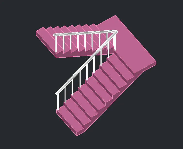
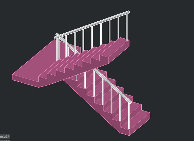
- Repeat the above procedure to create the other flight.
STEP 8
- Enter CO in the command line to select the Copy tool.
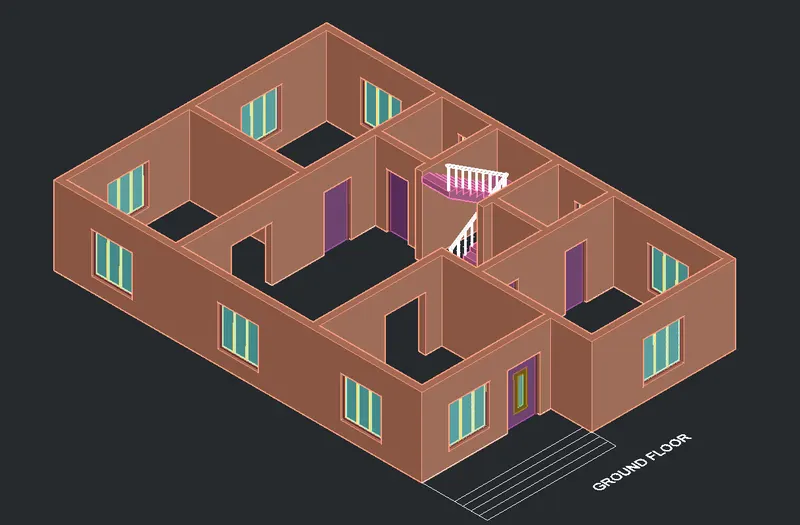
- Select the window, doors, ventilator and the stairs individually and copy them to their desired locations.
- Use 3DROTATE tool to rotate the objects as required.
- 3DORBIT command is used to control the viewing of the model when copying the doors, windows, ventilators and stairs to their respective locations.
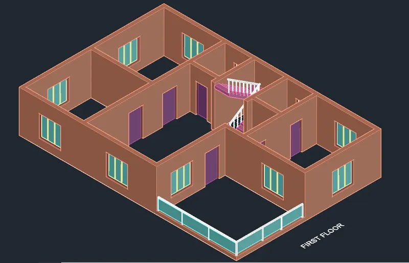
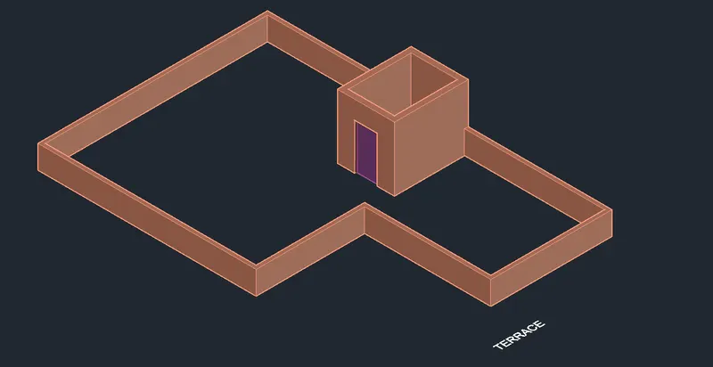
STEP 9
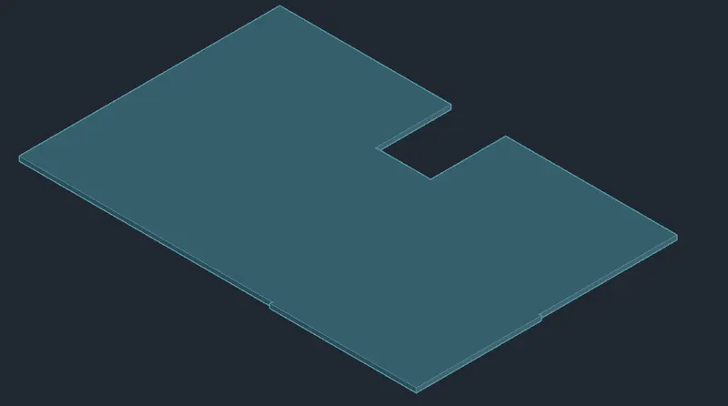
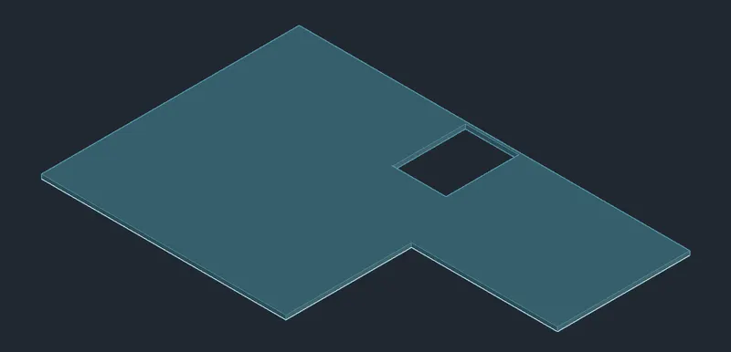
- Enter POLY in the command line to select the POLYLINE tool.
- Create a outline of the floor.
- Press Esc.
- Move the floor outline to a different location.
- Create a BOUNDARY of the outline.
- EXTRUDE it to a height of 600 to create the plinth.
- COPY it to the base of the ground floor model.
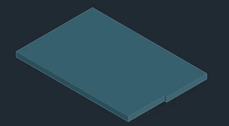
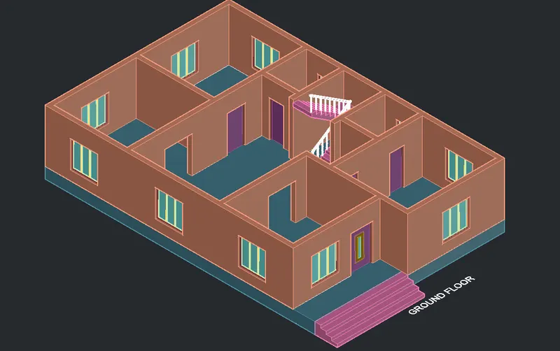
- Similarly create the floor slabs for the first floor and the terrace levels.
- Provide thickness of 150 mm.
Step 10
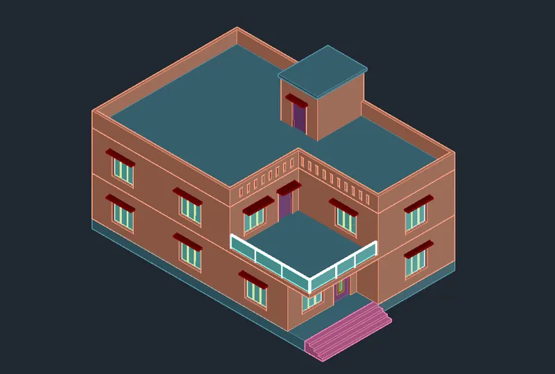
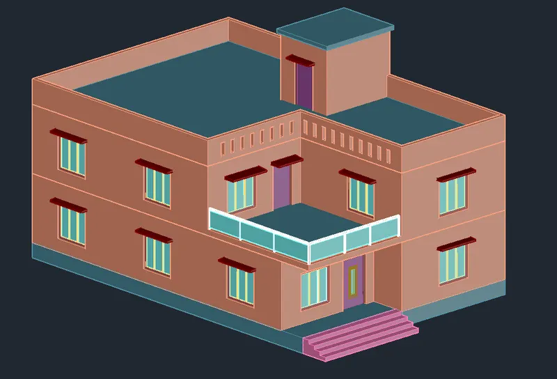
- Enter M in the command line to invoke the MOVE tool.
- Move each component of the building to its suitable position and assemble the whole model.
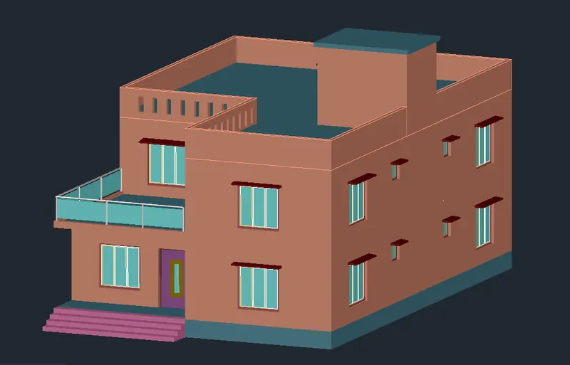
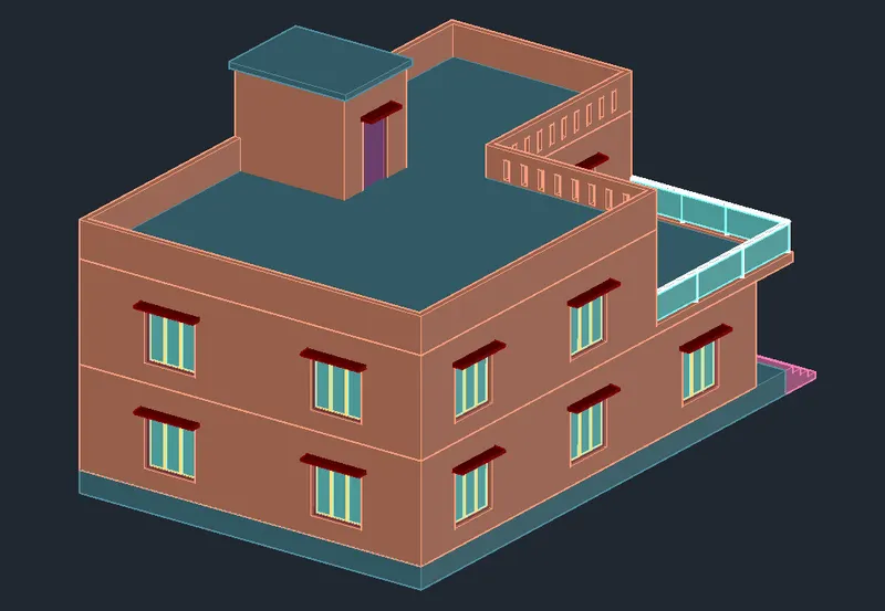
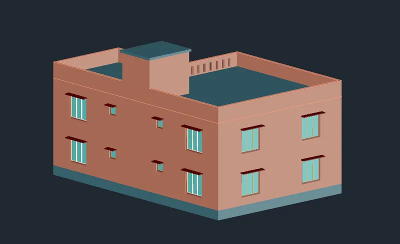
- Enter UCS in the command line.
- Select the World option.
- Enetr PLAN in the command line.
- Draw a Rectangle.
- Extrude it to a height of -50.
- Again go to Home view option in the view cube.
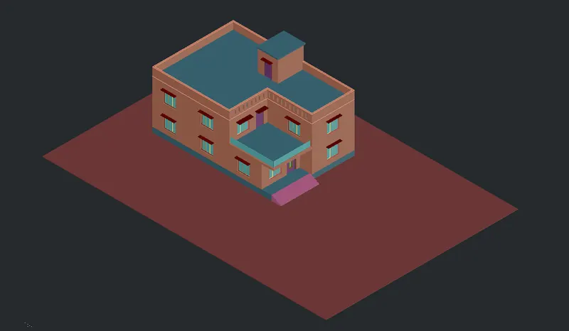
STEP 11
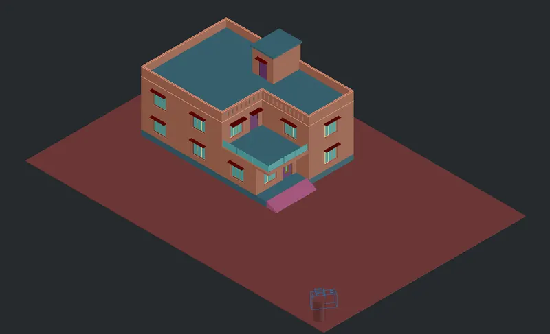
- To create a camera view, first draw a circle, extrude it to a suitable height.
- Enter CAMERA in the command line.
- Place the camera at the top of the cylinder created earlier.
- Specify the target location.
- Name the Camera view as Caml.
- From the Visualise panel the Sun Status can be adjusted and the Light can be created.
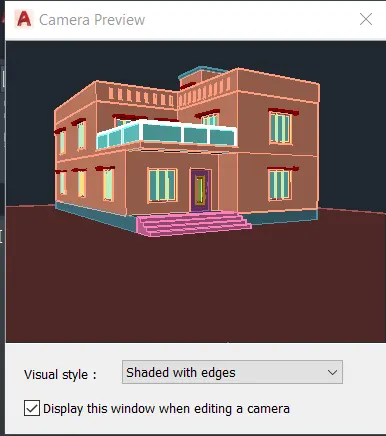
- Enter V in the command line.
- In the View Manager Dialog Box select the Caml view.
- Click Set Current OK.
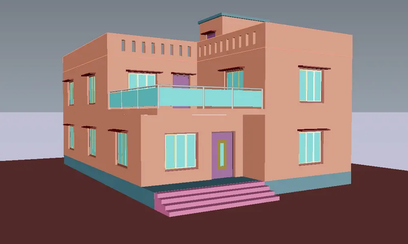
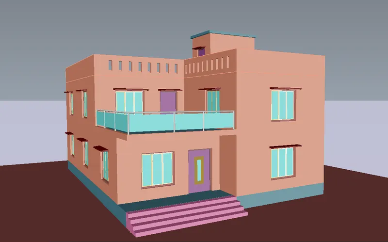
- Using the Navigation wheel the view can be adjusted.
- Save New View as Cam2.
STEP 12
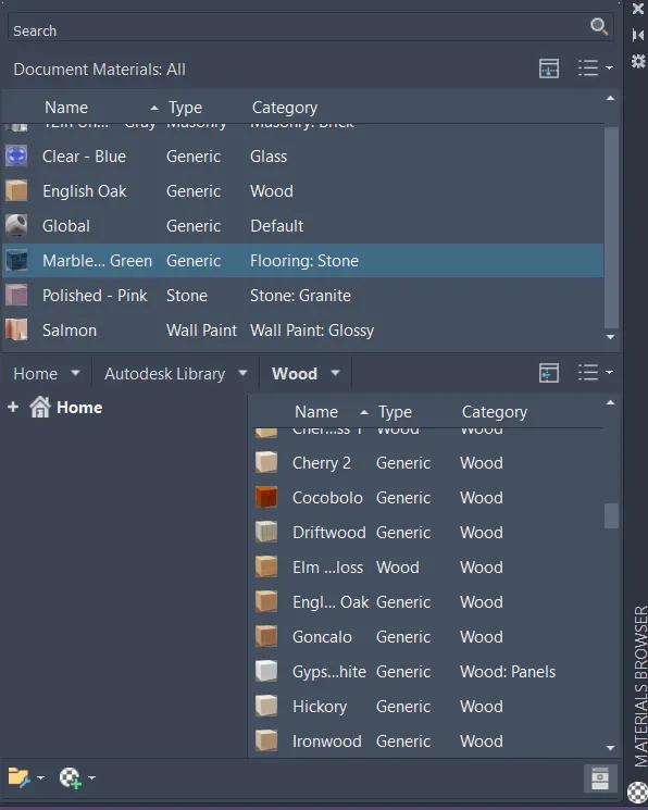
- Enter MAT in the command line to open the MATERIALS BROWSER.
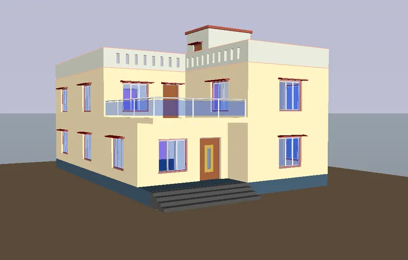
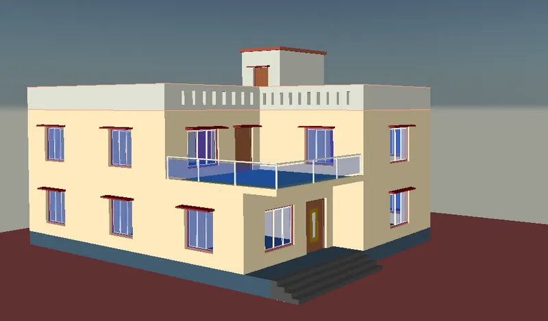
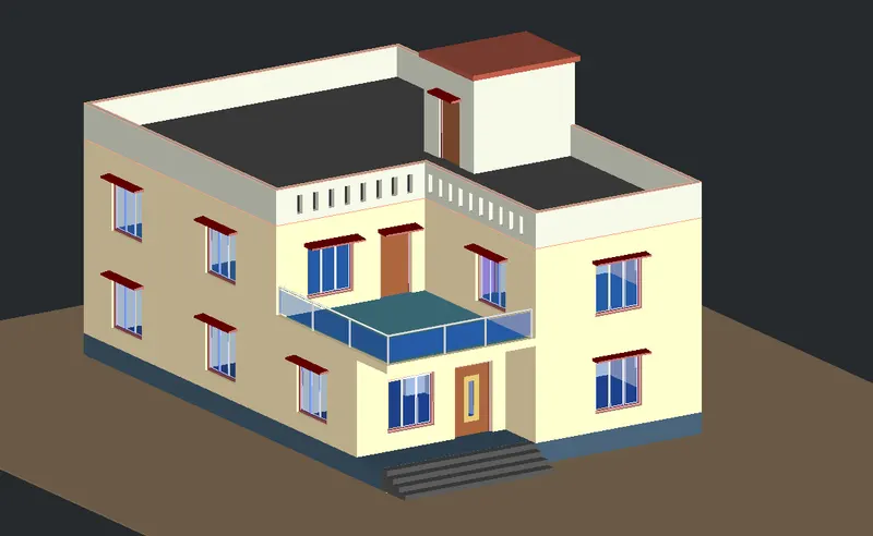
- Assign Materials to different components of thr building model by selecting them individually.
- Close the Materials Dialog box.
- Save the drawing.
STEP 13
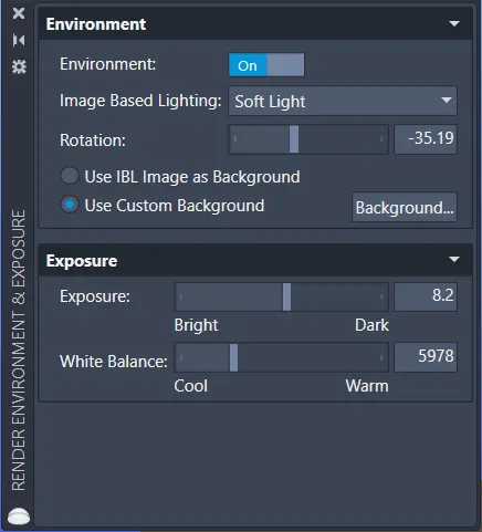
- Go to Visualise>Render drop down list>Render Environment and Exposure.
- Turn On Environment and make other suitable adjustments as required.
- Next adjust the Date and Time under Sun Status.
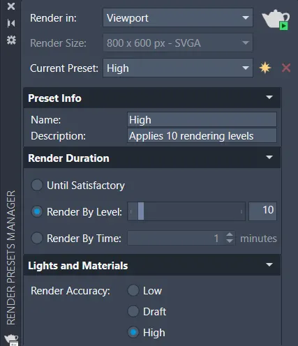
- Open the Render Preset Manger dialog box.
- Select Render in> Viewport.
- Make other chages as required.
- Close the Dialog box.
- Click on the Render icon on the panel.
RESULT: