Drafting of various geometries using Chamfer, Fillet tool in AutoCad
Q-1:-
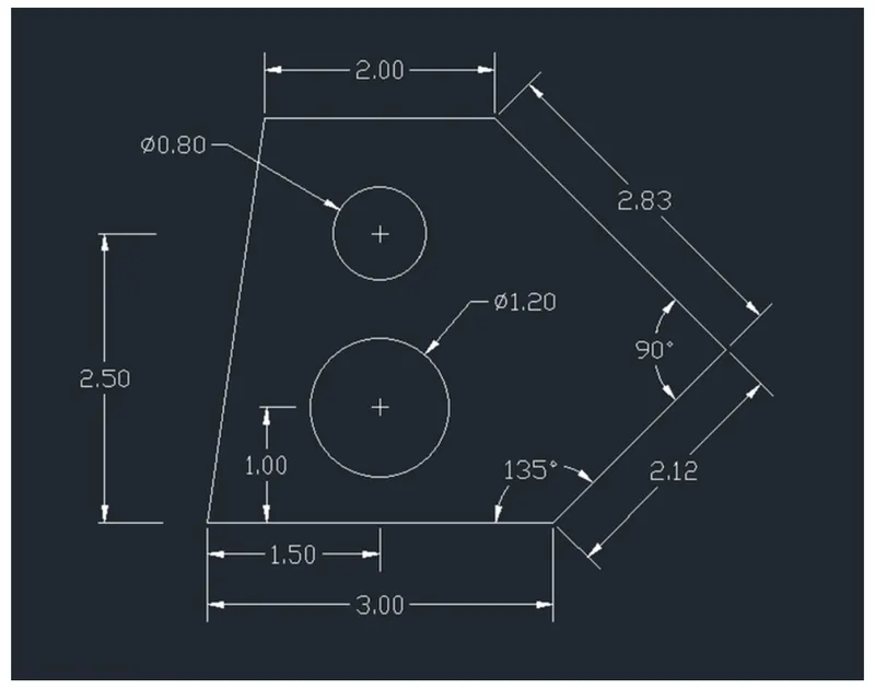
1. Aim: To draw the given geometry in AutoCAD software using unit of measurement as decimal unit.
Introduction
Various commands used to draw the geometry.
- QNEW command
- Line command
- Circle command
- Dimensions
Procedure
- Open AutoCAD software.
- Type QNEW in command box and press enter.
- In wizard setting select advanced setup.
- In advanced setup select unit of measurement as decimal with precision of 0.00
- Select angel of measurement as decimal degrees with precision 0.
- Select direction of angle measurement as east
- Select orientation of angle, measurement as counterclockwise and finish the setting.
- Type L in command box and press enter
- Specify first point as 5,5 and press enter.
- Specify next point as @3.00<0 and press enter.
- Specify next point as @2.12<45 and press enter
- Specify next point as @2.83-135 and press enter.
- Specify next point as @2<180 and press enter.
- Then click on the close option in the cammand box
- Type C in the command box and press enter.
- Specify center of the circle as 6.50,6.00 and press enter.
- Specify radius of circle as 0.60 and press enter.
- Again, type C in command box and press enter.
- Specify center for the circle as 6.50,7.50 and press enter.
- Specify radius of circle as 0.40 and press enter.
- Give the dimensions to the geometry using dimension tools.
Result
The output in AutoCAD software using above mentioned procedure is as follows.
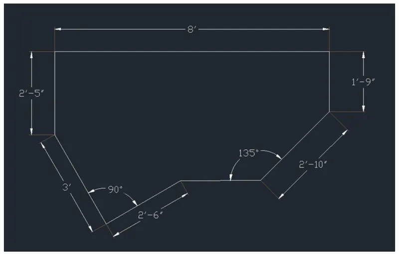
2. Aim: To draw the given geometry in AutoCAD using architectural unit of measurement
Introduction
Various commands used to draw the geometry.
- QNEW command
- Line command
- Dimensions command
Procedure
- Open AutoCAD software.
- Type QNEW in command box and press enter.
- in wizard setting select advanced setup.
- In advanced setup select unit of measurement as architectural with precision of 0'-0"
- Select angle of measurement as decimal degrees with precision 0.
- Select direction of angle measurement as east
- Select orientation of angle, measurement as counterclockwise and finish the setting.
- Type L in command box and press enter
- Select start point of line and specify next point as @2'-6"<210 and press enter
- Specify next point as @3'-0"<120 and pross enter.
- Specify next point as @2'-5"<90 and press enter.
- Specify next point as @8'-0"<0 and press enter.
- Specify next point as @1'-9"<270 and press enter.
- Specify next point as @2'-10 "<225 and press enter.
- Click on close option in command box.
- Using the dimensions tool give the dimensions to the geometry.
Result
The output in AutoCAD software using above mentioned procedure is as follows.
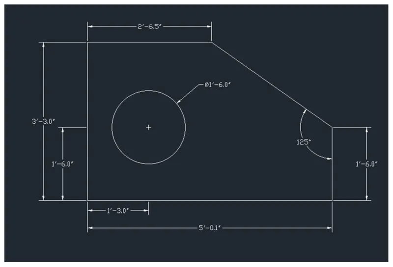
3. Aim: To draw the given geometry in AutoCAD software using engineering unit of measurement.
Introduction
Various commands used to draw the geometry.
- QNEW
- Line command
- Circle command
- Dimensions command
- Chamfer command
Procedure
- Open AutoCAD software.
- Type QNEW in command box and press enter. In wizard setting select advanced setup.
- In advanced setup select unit of measurement as engineering with precision of 0'-0.0"
- Select angel of measurement as decimal degrees with precision 0.
- Select direction of angle measurement as east
- Select orientation of angle, measurement as counterclockwise and finish the setting.
- Type rec in command box and press enter.
- Specify first corner point as 10'-0.0,10'-0.0" and press enter.
- Select dimension option in command box, specify length for rectangle as 5'-0.1" and press enter.
- Specify width of rectangle as 3-3.0 and press enter.
- Position the cursor in first quadrant and right click and select enter
- Type CHA in command box and press enter.
- Click on distance option in command box and specity first chamfer distance as 1-90, press enter
- Specity second chamfer distance as 2-5.6" and press enter
- Select first line as vertical line of right top comer and second line as horizontal line of right top comer of rectangle it will create chamfer.
- Now type C in command box and press enter
- Specity center of the circle as 11-30 11.6.0' and press enter
- Click on diameter option in command box and specify diameter as 1-8.0° and press enter
- By using the dimensions tool give the dimensions for line after setting unit of length measurement asengineering in dimension setting also.
Result
The output in AutoCAD software using above mentioned procedure is as follows
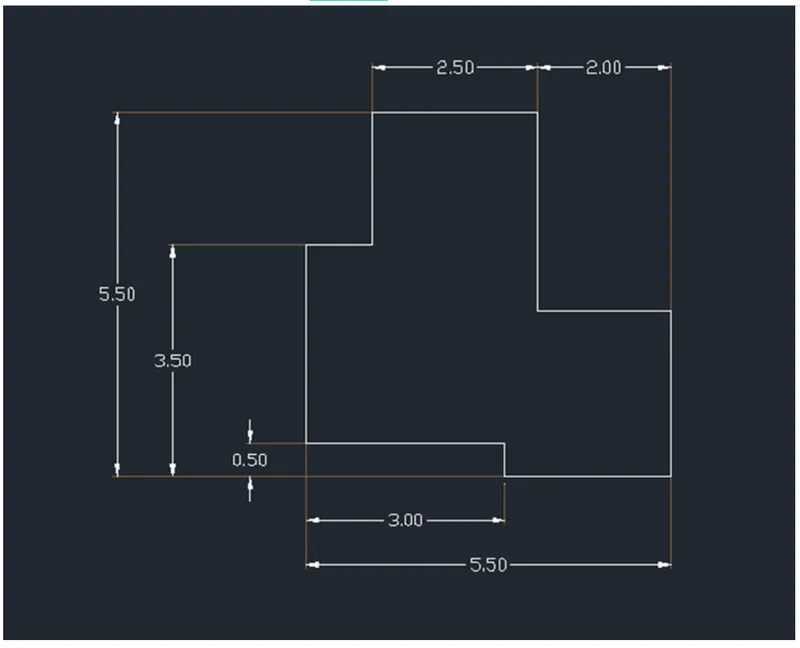
4. Aim: To draw the given geometry using decimal unit of measurement.
Introduction
Various commands used to draw the geometry.
- QNEW command
- Line command
- Dimensions command
Procedure
- Open AutoCAD software.
- Type QNEW in command box and press enter.
- In wizard setting select quick setup.
- In quick setup select unit of measurement as decimal with precision of 0.00.
- Type L in command box and press enter.
- Make sure ortho is on in the status bar.
- Specify first point, position the cursor in right direction, type distance 3.00 and press enter.
- Position the cursor in downward direction, type distance 0.50 and press enter.
- Position the cursor in up direction, type distance 2.5 and press enter.
- Position the cursor in left direction, type distance 2.00 and press enter.
- Position the cursor in up direction, type distance 3.00 and press enter.
- Position the cursar in left direction, type distance 2.5 and press
- Specify first point, position the cursor in right direction, type distance 3.00 and press enter.
- Position the cursor in downward direction, type distance 0.50 and press enter.
- Position the cursor in up direction, type distance 2.5 and press enter.
- Position the cursor in left direction, type distance 2.00 and press enter.
- Position the cursor in up direction, type distance 3.00 and press enter.
- Position the cursor in left direction, type distance 2.5 and press enter.
- Now, position the cursor in down direction, type distance 2.00 and press enter.
- Position the cursor in left direction, type distance I and press enter.
- Click on the close option in command box.
- Give the dimensions to the lines using dimension tool.
Result
The output in AutoCAD software using above mentioned procedure is as follows.
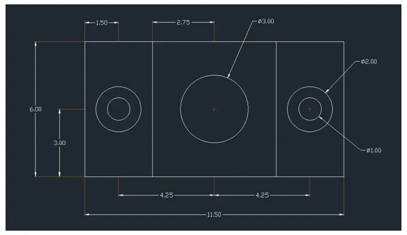
5. Aim: To draw the given geometry in AutoCAD software using decimal unit of measurement.
Introduction
Various commands used to draw the geometry.
- QNEW command
- rectangle command
- Circle command
- Dimensions command
Procedure
- Open AutoCAD software.
- Type QNEW In command box and press enter.
- In wizard setting select quick setup.
- In quick setup select unit of measurement as decimal with precision of 0.00.
- Make sure that object snap mode of status bar is on.
- Make sure center and geometric center visibility is on in the object snap setting.
- Type rec in command box and press enter.
- Specify first corner point of rectangle.
- Select area option in command box.
- specify area for rectangle as 18 and press enter.
- Choose length option in command box.
- Specify length of rectangle as 3 and press enter.
- Type rec in command box and press enter.
- Specify first corner point of rectangle as right bottom corner of previous rectangle.
- Select dimension option in command box.
- specify length for rectangle as 5.5 units and press enter.
- Specify width of rectangle as 6 and press enter.
- Position the cursor in first quadrant and right click and select enter.
- Type rec in command box and press enter.
- first corner point of rectangle as right bottom corner of last rectangle.
- Select area option in command box, specify area for rectangle as 18 and press enter.
- Specify length of rectangle as 3 and press enter.
- Type C in command box and press enter.
- Specity center of circle as geometric center of first rectangle and specify radius of circle as 1 unit and press enter.
- Again, type C in command box and press enter.
- Specify same center as that of previous circle and specify radius of circle as 0.5 units and press enter.
- Type C in command box and press enter.
- Select center of circle as geometric center of second rectangle and specify radius as 1.5 units and press enter
- Again, type C in command box and press enter.
- Specity center of circle as geometric center of last rectangle and specify radius of circle as 1 unit and press enter.
- Again, type C in command box and press enter.
- Specify same center as that of previous circle and specify radius of circle as 0.5 units and press enter.
- Give the dimensions to the geometry using dimension tool.
Result
The output in AutoCAD software using above mentioned procedure is as follows.
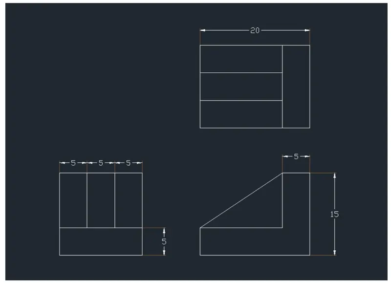
6. Aim: To draw the given geometry in AutoCAD software using decimal unit of measurement.
Introduction
Various commands used to draw the geometry.
- QNEW command
- XLine command or construction line command
- Offset command
- Trim command
- Dimensions command
Procedure
- Open AutoCAD software.
- Type ONEW in command box and press enter
- In wizard setting select quick setup.
- In quick setup select unit of measurement as decimal with precision of 0 Type XL in command box to draw construction line and press enter
- Select horizontal option in command box and draw two construction lines at certain distance.
- Again, type XL in command box and press enter.
- Choose offset option in command box and specify offset distance as 5 units and press enter.
- Take three offsets to each drawn construction lines.
- Type XL In command box press enter.
- Choose vertical option in command box and type two vertical construction lines at certain distance apart from each other
- Again, type XL in command box and press enter.
- Choose offset option in command box and specify offset distance as 5 units and press enter.
- Take four offsets to each drawn construction lines, it will create the block pattern.
- Type TR in command box and press enter.
- Trim the extra extended construction lines using trim tool.
- Using the same trim option trim the unnecessary lines in each block to get desired geometry.
- Using the dimensions tool give the dimensions to the geometry.
Result
The output in AutoCAD software using above mentioned procedure is as follows.
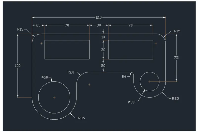
7. Aim: To draw the given geometry in AutoCAD software using decimal unit of measurement.
Introduction
Various commands used to draw the geometry.
- QNEW command
- Line command
- rectangle command
- Circle command
- Fillet command
- Arc command
- Dimensions command
Procedure
- Open AutoCAD software.
- Type QNEW in command box and press enter
- in wizard setting select quick setup.
- in quick setup select unit of measurement as decimal with precision of 0.
- Make sure that object snap mode of status bar is on.
- Make sure center, midpoint and endpoint visibility is on in the object snop setting.
- Choose line tool and specify first point as 100,100 and specify next point as 40 <270, press escape.
- Choose Arc tool and select start, center and angle option.
- Select start point as bottom end of the line and specify center as @35 <180 and included angle as 180 and press enter.
- Type C in command box and specity center as geometric center obove of draw arc
- Specify radius of circle as 25 units and press enter.
- Again, choose the line tool and specify start point as other end of arc.
- Specify next point of line as @100<90 and press enter.
- Specify next point as @210<0 and press enter.
- Specify next point as @75<270 and press enter.
- Choose the arc tool from ribbon and select the start, center and angle option.
- Specify start point as bottom end of just drawn line and center as @25<180 and press enter.
- Specity included angle as angle as 180 and press enter.
- Choose line tool from ribbon and specify first point as end point of the just drawn arc.
- Specify next point as @15<90 and press enter.
- Now, close the geometry by joining the endpoint of line with star point of drawing geometry.
- Type C in command box and select center of circle as center of right arc.
- Specity radius of circle as 15 and press enter.
- Type REC in command box and press enter.
- Specify first point of rectangle as 50,120 and press enter
- Specity radius of circle as is and press enter.
- Type REC in command box and press enter.
- Specify first point of rectangle as 50,120 and press enter.
- Choose dimension option in command box.
- Specify length of rectangle as 70 and width as 30, specify other corner point of rectangle in first quadrant side Type F in command box and press enter.
- Click on multiple option in command box followed by radius option.
- Type fillet radius as 15 units and press enter.
- Select objects as top left corner lines of geometry for first fillet and top right corner lines of geometry for next filleting
- Type F in command box and press enter.
- Choose the radius option in command box and type fillet radius as 20 units and press enter.
- Select the intersecting corner lines where we want to draw the fillet
- Again, Type Fin command box and press enter.
- Choose the radius option in command box and type fillet radius as 6 units and press enter.
- Select the intersecting corner line to draw fillet
- Select the intersecting corner lines where we want to draw the fillet of 6 unit radius. - By using the dimension tools give the dimensions to the geometry.
Result
The output in AutoCAD software using above mentioned procedure is as follows.
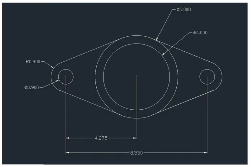
8. Aim: To draw the given geometry in AutoCAD software using decimal unit of measurement.
Introduction
Various commands used to draw the geometry.
- QNEW command
- Circle command
- Arc command
- Dimensions command
Procedure
- Open AutoCAD software.
- Type QNEW in command box and press enter
- in wizard setting select quick setup.
- in quick setup select unit of measurement as decimal with precision of 0.000
- Make sure that object snap mode of status bar is on
- Type C in command box and press enter
- Specity center for the circle and specity radius of circle as 2.5 units and press enter
- Choose circle option in home tab of ribbon and select center diameter option
- Specity center of circle as center of first drawn circle and type diameter as 4 units and press enter.
- Type C in command box and press enter.
- Specity center of circle at distance of 4.275 units from the center of first drown circle
- Click on diameter option in command box and specify diameter as 0.9 units and press enter
- Choose Arc tool in home tab of ribbon and select center, start and angle option.
- Specity center as center of last drawn circle and start as @0.9<90 and press enter.
- Specify included angle as 180 and press enter.
- Make sure tangent option of object snap is on.
- Draw the tangents from the star and end point of arc to the top and bottom point of the 5 unit diameter circle
- Repeat the same procedure on right hand side of centrally drawn circle.
- Give the dimensions to the geometry using dimension tool.
Result
The output in AutoCAD software using above mentioned procedure is as follows.
9. Aim: To draw the given geometry using AutoCAD software.
Introduction
Various commands used to draw the geometry
- QNEW command
- Line command
- Circle command
- Trim command
- Dimensions command
Procedure
- Open AutoCAD software.
- Type QNEW in command box and press enter.
- In wizard setting select quick setup.
- in quick setup select unit of measurement as architectural with precision of G-0", Make sure tangent option in object snap mode is on
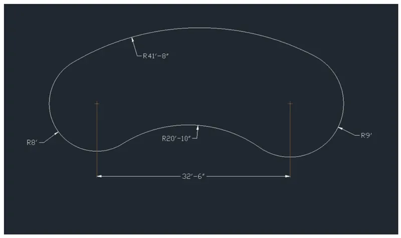
- Choose line tool and draw horizontal line of length 32'-6"
- Type C in command box and press enter
- Select center of circle as first endpoint of line and specify radius as 8'-07" and press enter.
- Again, type C in command box and press enter
- Select center of circle as other end point of horizontal line and specity radius as 9-0 and press Choose erase tool from home tab of ribbon and erase the drawn horizontal line
- Choose circle option in home tab of ribbon and select tangent, tangent and radius option
- Select first tangent as top of 8' circle, second tangent as top of 9' circle and specify radius of circle os 41'-8"ond press enter
- Again, choose the circle option from home tab of ribbon and select tangent, tangent and radius option. Select first tangent as bottom of 8' circle, second tangent as 9 circle and specify radius as 20-10° and press enter
- Type TRIM in command box and press enter.
- Trim the unwanted lines to get the desired geometry Give the dimensions to the geometry using dimension tool.
Result
The output in AutoCAD software using above mentioned procedure is as follows.
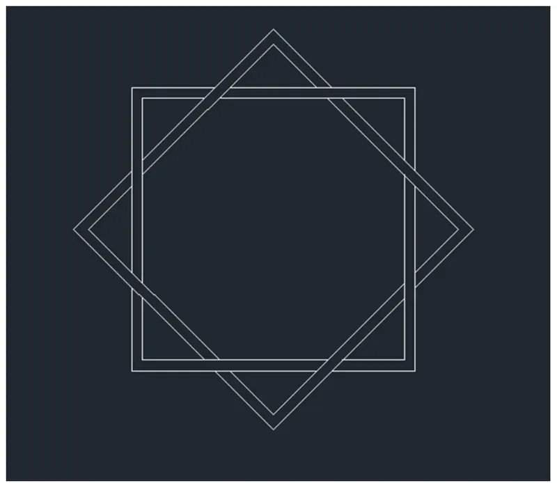
10. Aim: To draw the given geometry using AutoCAD software.
Introduction
Various commands used to draw the geometry.
- QNEW command
- Rectangle command
- Rotate command
- Trim command
- Dimensions command
Procedure
- Open AutoCAD software.
- Type QNEW in command box and press enter
- In wizard setting select quick setup.
- In quick setup select unit of measurement as decimal with precision of 0 and angle of measurement as decimal degrees with precision 0.
- As the dimensions of geometry are not given let us assume it consists of square of side 10 units.
- For that type rec in command box and press enter.
- Select first corner point of rectangle and choose dimension option in command box.
- Specify length of rectangle as 10 units and width as 10 units and press enter
- Type O in command box and press enter.
- Type RO in command box and press enter.
- Select the object and press enter.
- Select the base point as geometric center of rectangle and choose the copy option in command box
- Specify rotation angle as 45 and press enter.
- Type TRIM in command box and press enter.
- Trim the extended lines to get the desired geometry.
Result
The output in AutoCAD software using above mentioned procedure is as follows
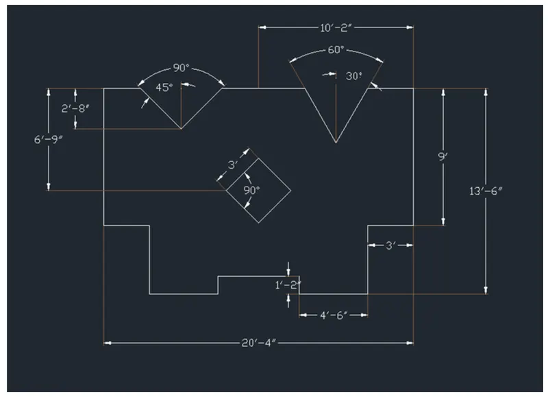
11. Aim: To draw the given geometry in AutoCAD software using architectural unit of measurement.
Introduction
Various commands used to draw the geometry.
- QNEW command
- Line command
- Chamfer command
- Mirror command
- Erase command
- Dimensions command
Procedure
- Open AutoCAD software.
- Type QNEW in command box and press enter.
- In wizard setting select quick setup.
- In quick setup select unit of measurement as architectural with precision of 0'-0" and unit of angle measurement as decimal degree with precision of 0.
- Type L in command box and press enter.
- Select first point of line and specify next point as @5'-1"180 and press enter.
- Specify next point as @9'-0"<270 and press enter.
- Specify next point as @3'-0"<0 and press enter.
- Specity next point as @4'-6"<270 and press enter.
- Specify next point as @4'-60" and press enter.
- Specify next point as @1'-2"<490 and press enter.
- Specify next point @2'-8"<0 and press enter.
- Specify next point as @3'-2"<90 and press enter.
- Specity next point as 3'-0"<135 and press enter.
- Specify next point as @3'-0"<45 and press enter and press esc button
- Type MIR in command box and press enter.
- Select the entire objects by using crossing window and press enter.
- Select first point of mirror line as bottom corner point of object and second point of mirror line as top corner point of line.
- In command box choose no option for not erasing the source object.
- Type E in command box and press enter.
- Select the object to erase as central vertical line of object and erase it.
- Choose line tool and specity start point as start point of object in left side and specify next point as @2'-8"<270 and press enter
- Type CHA in command box and press enter.
- Choose the angle option in command box and specify chamfer length on first line as 2'-8" and press enter.
- Specity chamfer angle from first line as 45 and press enter.
- Select first line as vertical line and second line as horizontal line, it will create chamfer
- Type MIR in command box and press enter.
- Select inclined line and press enter.
- Select first point of mirror line as bottom end point of inclined line and second point of mirror line as any top point in vertical direction.
- Similarly, Choose line tool and specify start point as start point of object in right side and specify next point as @3'-7"<270 and press enter.
- Type CHA in command box and press enter.
- Choose the angle option in command box and specify chamfer length on first line as 2'-8" and press enter.
- Specity chamfer angle from first line as 45 and press enter.
- Select first line as vertical line and second line as horizontal line, it will create chamfer
- Type MIR in command box and press enter.
- Select inclined line and press enter.
- Select first point of mirror line as bottom end point of inclined line and second point of mirror line as any top point in vertical direction.
- Similarly, Choose line tool and specify start point as start point of object in right side and specify next point as @3'-7"<270 and press enter.
- Type CHA in command box and press enter.
- Choose the angle option in command box and specify chamfer length on first line as 3'-7" and press enter.
- Specify chamfer angle from first line as 30 and press enter.
- Select first line as vertical line and second line as horizontal line, it will create chamfer.
- Type MIR in cammand box and enter.
- Select inclined line and press enter.
- Select first point of mirror line as bottom end point of inclined line and second point of mirror line as any top point in vertical direction.
- By using the line tool close the geometry.
- Using dimensions tool specify dimensions to the geometry.
Result
The output in AutoCAD software using above mentioned procedure is as follows.