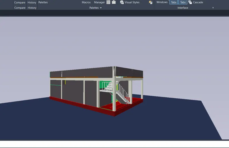
Project 2_Creating a 3D rendered model for a Residential Building in AutoCad
1.Aim: To create the 3d model of building and rendering view unit in the Auto cad engineering system.
- Auto Cad 3d modeling is developed to plot the modules in 3 dimensional or as to develop the solind model of a unit.
- In Auto cad length ,width and height is also plotted in the same plane. In the auto acd 2d Only one plane formed with X and y axis is only used while in the Auto cad 3d model Z axis is also used to plot the height of the model with repect to the X and Y axis.
- In the Auto cad 3d model all the views of the model can be visible simultaneously using the view cube option.
- After developing the 3d model of the individual house, the rendered view of the building is also dveloped and the material properties is assigned to the building units using the material browser option.
Procedure :
- Click on new File and create the new template for potting the drawing
- Now enter units (un) command and select the engineering system in the units and also set the precision of the units and insertion scale to inches and click on ok.
- Now the lay out plan is plotted using the various commands.The outer line of the building is plotted using the line or poly line or rectangle command to a size of 43'6.5" and 25'.
- Now enter offset distance of 9" for all the four sides which forms the external walls of the building.
- Now using the offf set command the bed room walls are plotted to an off set distance of 11'7.5" and 11'6" from the vertical external walls and with an offset distance of 12' from the horizontal external walls.
- Now using the trim command trim the corners edges which are merged and the boundary wall edges are formed.
- In this way using the offset command the walls of the different rooms are plotted with respect to the sizes of the rooms and the plan of the drawing is plotted with the respective position of the columns and the walls etc.
- Now the drawing is changed into the 3d modeling unit and the 3dmodeling unit with the rendering view of the building is created. The walls of the building are extruded to various levels.
- Enter region or boundry command in the command bar and the regions of the walls are created by selecting the regions or the closed boundry of the walls and columns.
- Enter the extrude command in the command bar and the walls are selected and extruded to a height of the 6'6" that will be the lintel level, the walls are extruded upto lintel level because to provide the bearing of the lintel to be the lintel in the firm position.
- Now enter the rec command and plot the rectangless over the walls which are extruded and also plot the lintel at the wall top level i.e 6'6" from the floor level.
- Enter the region command and create the region for the lintel,now enter the extrude command and extrude the lintel to a size of 8" .
- Enter the rectangle command and plot the rectang;le over the lintel for the further extension of the walls and enter the region command and create the region for the walls over the lintel and as well as over the walls with no lintel also. Now enter the extrude command and extrude the walls over the lintel to the height of 2' and the walls with the no lintel to a height of 2'8".
- Now enter the rectangle and plot the rectangles over the walls which will be extruded to create the rooof beam. Enter the region command and create the region for the rectangles over the walls and enter the extrude command and extrude the rectangles over the walls to a height of the 1' and a roof beam will be created.
- Enter the rectangle command and create a rectangle over the total building and for the creation of the roof slab.Enter the region command and create the region for the rectangle and extrude to the thickness of 6".
- The columns in the bottom of the plan are now extrude to the full height of 12'8" and create the region for the rectangles of the columns and enter the extrude command and the columns are extruded to the full height of 12'8".
- The Stair case is plotted separetely and copied it to the necessary position in the 3d model unit. The side view of the stair case is plotedin the xy plane and then rotate with the 3d rotate command along z axis to an angle of 90 inthe command bar and then the stairr case is extruded to the height of 3'.
- The Hand rail and balustrades are created with the rectangle or cicle command which will depend on the shape of the hand rail and then it is exruded to the height of the balustrade is 2'10".
- Enter the circle command and create the circle over the stair with the radius of 2" and then enter the region command and create the region of the circle and extrude to the height of 2'10".Now enter the copy command in the command bar and copy the balustrade to all the stairs.
- The hand rail is plotted using the polyline command enter the polyline command in the command bar and join the centre points of all the balustrades and then sweep the circle along the path generated by joining the cetre points of the balustrades. Then the obtained staircase is copied and placed in the necessary position where we require in the 3d model unit.
- The parapet wall is created with rectangle command enter the rec command in the command bar and plot the rectangle to a size of the roof slab, Now enter the offset command in the command bar and then the offset the rectangle to a distance of 4" and enter the region command and create the region between the two rectangles and extrude the region of the parapet to a height of 3'.
- Now the total building is created to the 3d model unit then it is created for the rendering view and to assign the materials of the building.The rendered view is nothing but the view of the at a certain point with the fixed elevation.The rendered view is created with the camera command. Enter the camera in the command bar then the camera is displayed on the screen and adjust the camera in such a way that the whole building is covered from the camera point then enter the details of the location of the camera, Name of the camera view, the elevation of the camera and lens of the camera etc.
- The material of the building is assigned using the material browser option, In the material browser option there will be various kind of materials which can be assigned to the building units. Select the building unit like beam,wall,stair case, door or any other units of the building and select the material in the materail browser and click on 'Assign to the selected' option and then the unit changed in to the material which may be concrete,Brick,stone or any other material. By using the material browser we can easily get to know about the materials by which the building unit is formed.
- The shaded view gives the solid model of the modeling unit of the building it doesnot specify the surface and texture of the materials units of the building it says about the view which is made of solid volume.
- The rendered view differentiate the surface of the building unit by exhibiting the nature of materials which are finished or the building units made by the respective materials.
- The final rendered view of the building unit is formed as shown below.
The below rendered view diaplays the surface property of the materials by which the building unit is made.
- The rendered view is a view obtained by the focus of the camera towards the building.The camera view is the one in which the building is viewed from particulr angle with the fixed elevation in three dimensional way.
- The rendered view exhibits the plinth beam is made of the brick masonry surface.
- The walls of the rendered view states that the walls are made up of the grey masonry stone surface.The walls include the both external,internal and the parapet wall.
- The Columns and the stair case is generally casted with concrete but we may apply the finishing course made of various materials like granite, marble,tiles and other various types of stones.In the below redered view of the building unit the column are finished with the marble stone.
- In this way for a building unit all every individual unit various types of material properties can be assigned using the various kinds of materials in the material browser option.
- The rendered view of the building helps for the skilled and unskilled person to get to know about the material by which the building units are made.
- The final rendered view of an individual residential house obtained is shown below.