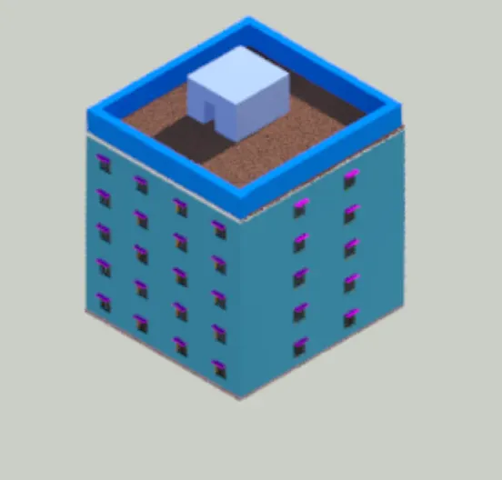
Project 2_Creating a 3D rendered model for a Residential Building in AutoCad
Aim - To crerate a 3D model of Residential Building .
Introduction -
i) A 2D plan is created in autocad and it is converted into 3D by using Autocad 3D Modeling .
ii) Auotocad is generally used for 2D drawings and then if necessary it is converted into 3D objects by using 3D Modeling
iii) To use 3D autocad , a user should be familiar with 3D commands which are mainly used such as Sweep , Extrude , Subtract ,
Union etc
iv) User also should be familiar with the Viewport features when working in 3D Models.
v) There are by default different views are available in 3D like Top view , SE ISOMETRIC , SW ISOMETRIC .etc So user needs to
understand how to work by using view cube options .
Followings are the 2D and 3D tools which are used in this project -
A) 2D Tools -
1) Line - It is a basic command which aren used in this project . Command L
2) Construction Lines - Construction line are helpful when we create a floor plan. It acts as a reference line for plan . Command XL
3) Arc - This command is used to draw a curve . For door openings we can directly used ARC command to draw the curve . Command Arc
4) Rectangle - Rectangle commads are used if the dimensions such as Length and Width are known , then we can directly draw the plan instead
of drawing by Line command . Command Rec
5) Erase - This command are used to delete the objects or line . Command Erase
6) Trim - This command also similar to Erase command . Command Trim
7) Copy - This command is used to create a copy of the object in specified dimensions or by specifying the reference point. You can create multiple
copies of the object . Command Copy
8) Mirror - This command is used to create a mirror image of the object by specifying the reference line or point . Command Mirror
9) Layers - Layers are the commands which is used for highlighting the lines by assigning the colour type and linetype . It controls the Visibility
of the object . Command - LA
10) Dimensions - This command is used to measure the dimensions of the object . There are various option in Dimensions .
For eg - To measure aligned dimensionsn - DIMALIGNED command used
To measure the dimensions from base - DIMBASE is used
To measure the dimensions from previous dimensions - DIMCONTINUE command used
11) Text - This command is used to show the Annotations to the particular object . Command DT is used
2) 3D Tools -
1) Sweep - This command is used to extrude the 2D objects by specifying the path . Command Sweep
2) Extrude - This is the most used command in 3D. This command helps to create a 3D object by extruding the 2D plan along the faces .
Before extruding the command a region should be create . Command Extrude
3) Union - This command helps to combine the two objects into single entity .
4) Subract - This command is used to subtract a particular objects from the other object.
For eg . For Eg if Rec is drawn and it is extruded at a certain height and If we want to create a hole in that section , Then Subtract
command is used .Circle is drawn at the surfaces and it is extruded at a ht of rectangle . and then selecting the Subtarct
command , Select the Rec and the subtract Circle object .
5) Rendering - It is a last command of 3D modeling to see the 3D view after assigning all the materials and properties . A view is created based
on materials and properties which we assign.
3) Assigning Material Properties -
i) Visualize tab - Material browser - Add materials
ii) Select the object which we have to assign the properties - Right click on material and Selection to apply object .
Procedure -
i) Open Autocad - click on Open New Drawing
ii) Make sure that your workspace setting is in Drafting and Annotations ( Because we have to create a plan in 2D )
iii) Now we have to set the Units - Command UN - Decimals - Milimeters -
iv) Set the LIMMAX and LIMITS
A)
Step 1) To create the 2D Floor plan ( of 4 Flats )
i) Command XL - to draw a horizontal and vertical construction lines for reference
ii) Command Offset - Take the offset of 230mm to draw the walls and Assumen internal wall of size 150mm
iii) Command Line , Rectangle , Offset are used to draw the 2D plan
iv) Provide Necesssary openings for Doors , Windows wherever necessary .
v) For Staircase - Assume Riser - 150mm
Tread - 250mm
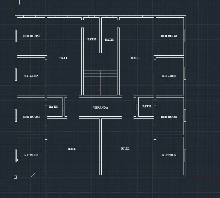
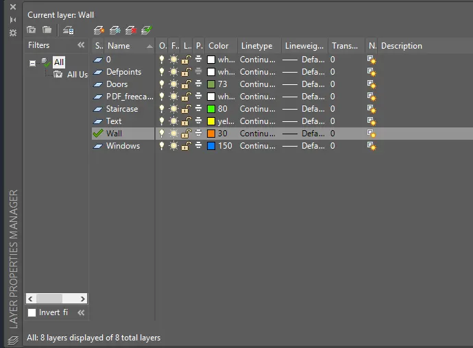
vi) Command LA - Add layers such as
i) Wall layer
ii) Doors
iii) Text
iv) Staris
v) Windows
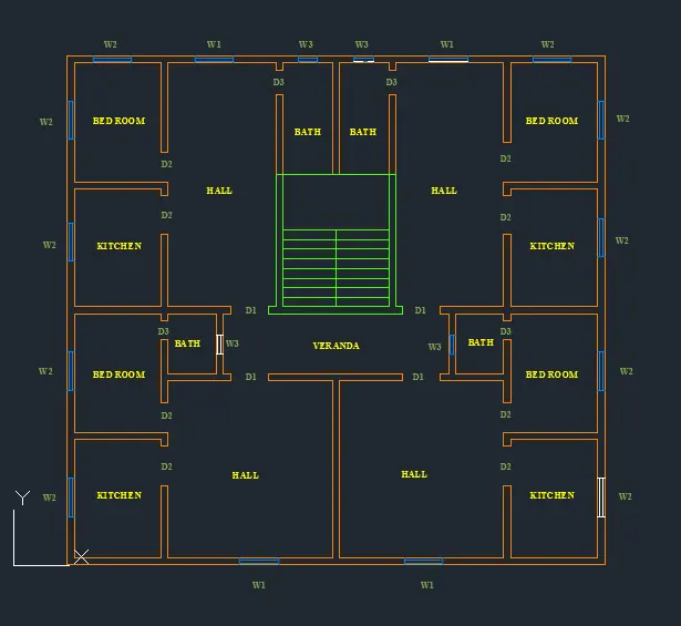
vii) Dimensions is done by using DIMLINEAR command -
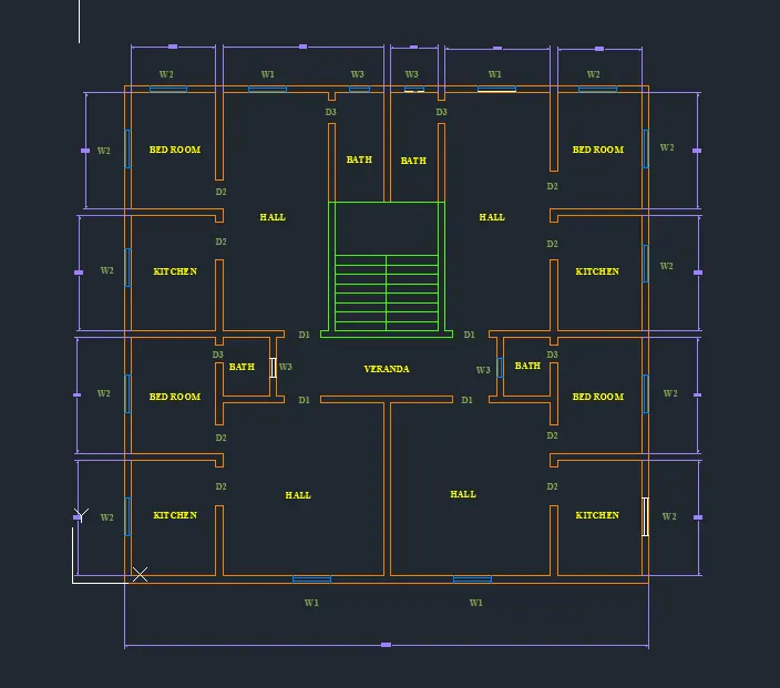
viii) Apply Lineweight to 0.30mm
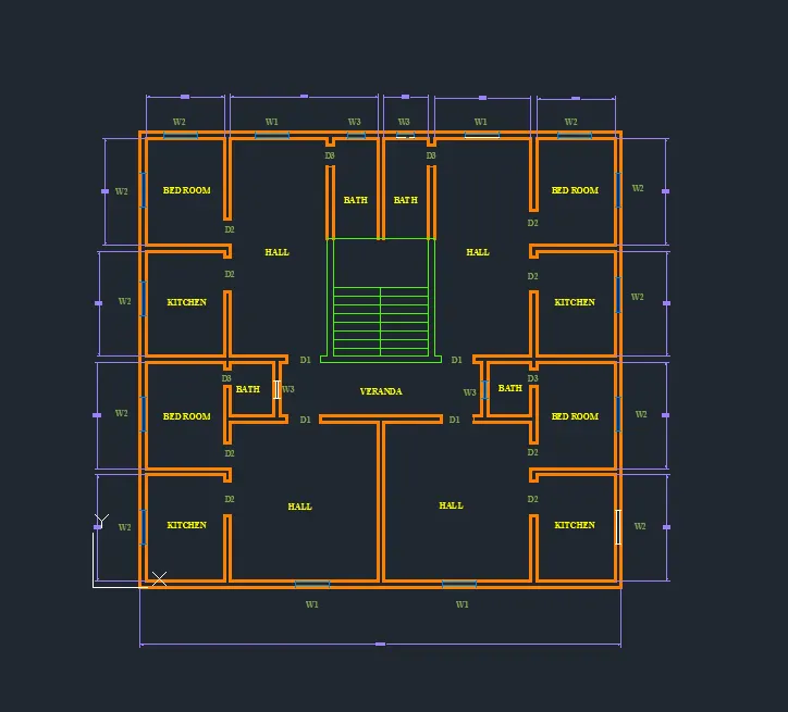
ix) 2D Floor Plan of (4 flats) are created .
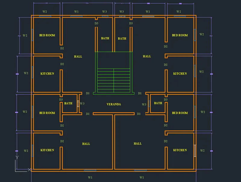
B)
Step 2) To convet 2D view to 3D view by using Autocad 3D
i) Now , change the workspace setting to Autocad 3D modeling and visualize style to 2D wireframe model
ii) Make a copy of plan and work on that plan .
iii) By default view will be SE ISOMETRIC
iv) Turn off all the layers except Wall layer
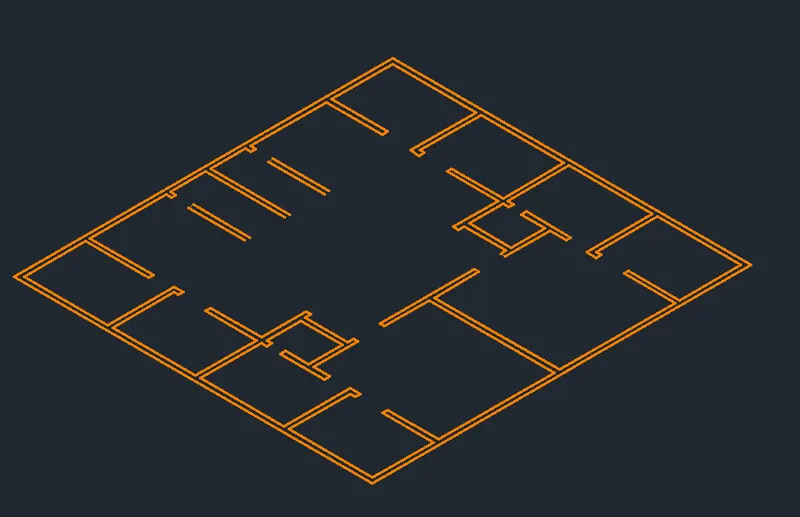
v) Now , we have to create a boundary before extruding the object
vi) Command BO - Pick up internal points - press Enter .
vii) Command Extrude - Extrude the object at a height 3.2 m
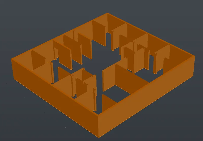
Step 3) Doors cutoffs
i) As we already have the openings of doors
ii) Draw the Rec at the top surface at top
iii) Assume the height of door is 2.1m
iv) Extrude the door from top to bottom at an height of 1.1 m
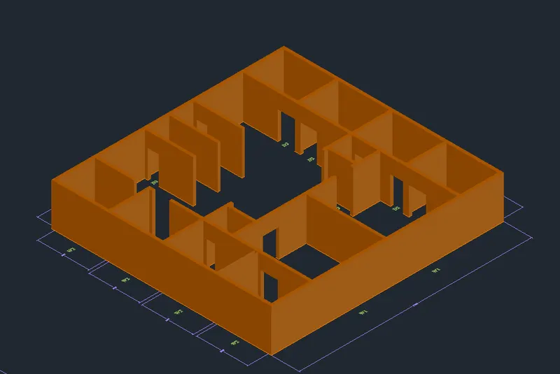
Step 4) Window Cutoff
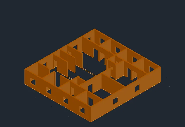
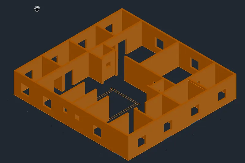
i) Just like door cutoff , Similarly we have to do it for Window cutoff also.
ii) Turn off the wall layer and Turn on the window layer
iii) Draw the rectangle at the window side and extrude it at an height of 800mm from bottom (plinth level) and 1100 mm from top.
iv) For Ventilators window extrude at an height of 1500mm from plinth level .
iv) Now using Subtract command , Subtract the windows from the wall .
View from SE ISOMETRIC
View from NW ISOMETRIC
Step 5) To create a Floor level
i) To create a floor leve first we have to draw a polyline at the top
ii) Command Polyline - Draw the line at the top from outer to outer portion of the building.
iii) After creating the polyline , Move the polyline to the base i.e 3200mm from top .
iv) After shifting the polyline at the plinth level , Extrude the polyline at a distance 200mm to create a floor level .
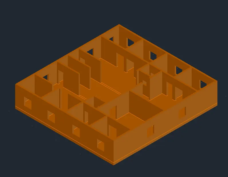
Step 6) Creating portion of Staricase and its cross section.
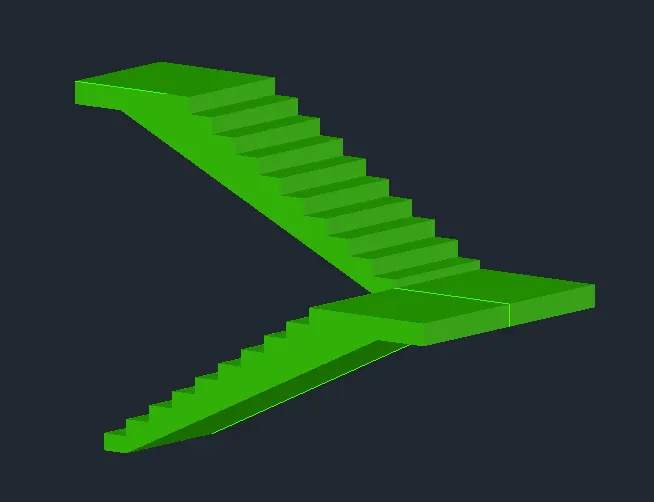
i) Turn on the staircase level .As we are providing dog-legged staircase
ii) Draw the rectangle at the staricase portion.
iii) Extrude the staricase wall at an height of 3200 mm ( which carries 1st flight , landing portion , 2nd flight .)
iv) So , Walls of staricase are extruded .
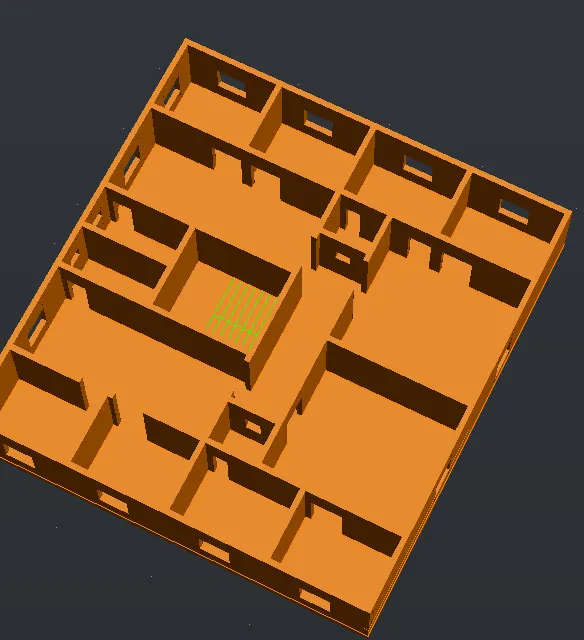
v) Now we have to draw the cross section of stairscase
vi) First draw the 2D plan of staricase which contains Riser and Tread . Size are already mentioned
vii) width of landing is provided 1500 mm and thickness of landing slab is 250mm
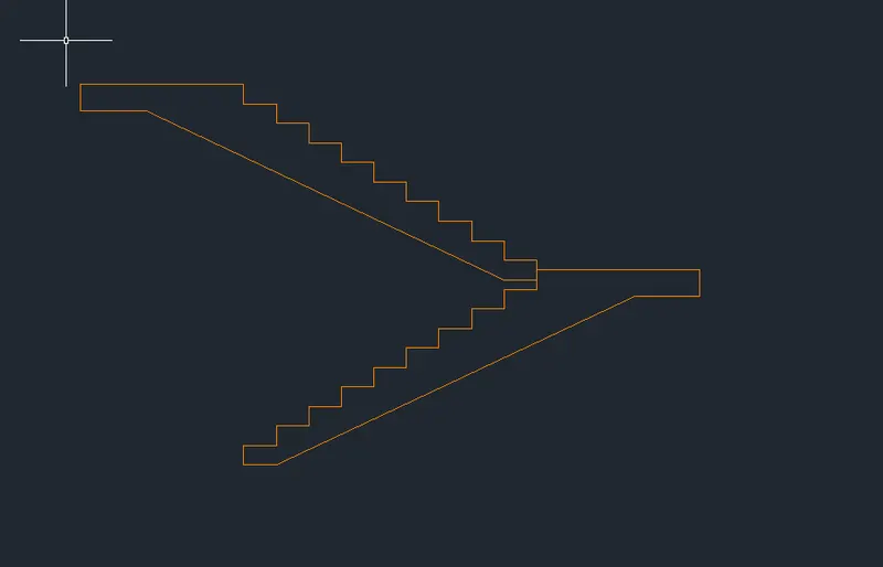
vii) Now , convert into the object into 3D , by extruding the command
viii) Before the Region should be created ,
ix) Command Boundary pick up the internal points and press Enter .
x) Extract the steps to create 1st Flight
xi) Similarly follow the same procedure to create the 2nd Flight .
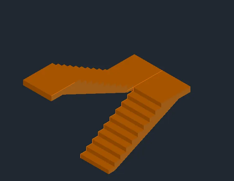
xii) Assign the layer of staircase , as w have drawn it by wall layer . Select the object - Right click - properties - Staircase layer
Step 7) Assigning Doors and Windows -
i) To create a Door D1
ii) Create a Rectangle of dimensions 1500 x 2100 mm
iii) Take the offfset of 100 mm on both side
iv) From the midpoint of the rectangle( on both sides) , draw a vertical line and Horizontal line from the midpoint
v) Take the offset of 50mm from both the line i.e upward and downward directions .
v) Assign the layer of Doors .
vi) Follow same procedure for other doors also.

For Windows -
i) Create a rectangle
ii) Command Rec 1
iii) Enter Length - 1200 mm
iv) Entter Width - 1300 mm
v) Create an offset of a distance 100mm and again 150 mm for both the window
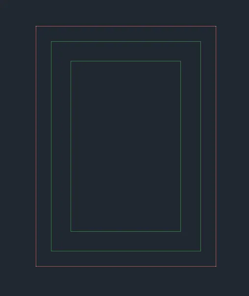
vi) Command Subtract - Select bigger region and subtract smaller region
vii) Follow the same procedure for all the three boxex.
viii) Command BO
ix) Pickup the internal points and press Enter .
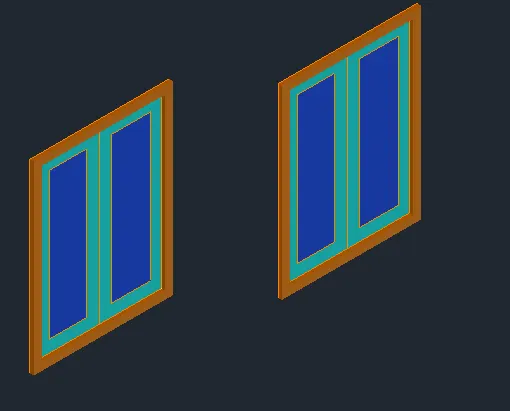
x) Command Extrude - Extrude the frame of the window .
Step 8) Assign the Materials to Windows and Doors -
i) Command MAT -
ii) Select the materials such as Glass and Wood
iii) Select the type of glass and windows whichever you want .
iv) Select the windows and door and right click the properties and assign to selection object .
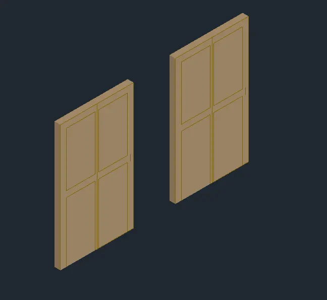
Step 9) Assign the doors and windows
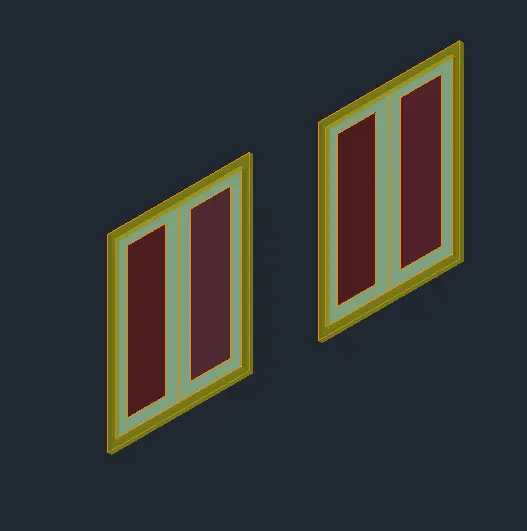
i) Make the copies of windows and Doors
ii) Command 3DMove -
iii) Move the doors to the respective openings for doors and windows .
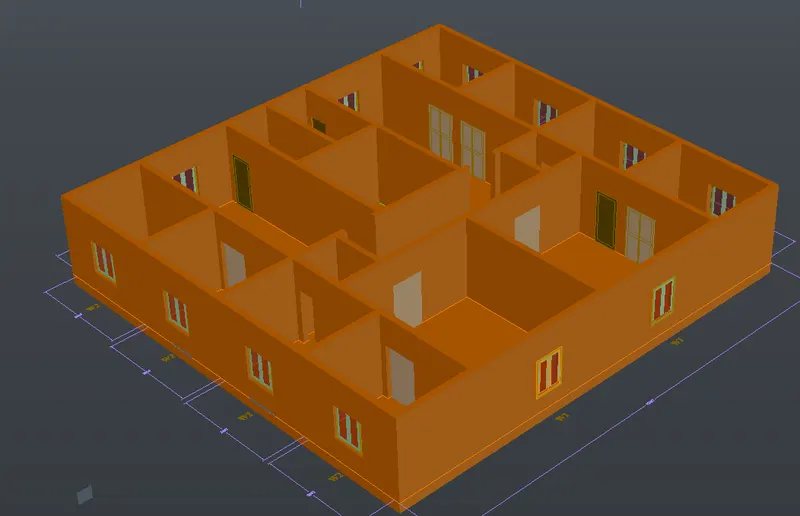
Step 10) Assign the materials to the remaining walls , internal walls etc
i) Command MAT
ii) Materials browser will open
iii) Select the properties from Autodesk Library - Select sub properties
iv) Select the object and assign the materials properties .
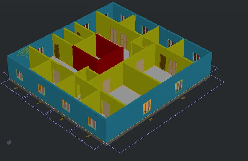
Step 11) Assigning lights
i) Assign the lights by creating the lights .
ii) To place a light at the top , for that change the view to Top view
iii) Draw the diagonal line where you want to keep the lights
iv) After creating a diagonal line , Create a light - Select which you want ( point light , distance light etc )
v) Place this light at the center of the diagonal line
vi) Increase the intensity factor to 30 .
vii) Follow the same procedure for other rooms also .
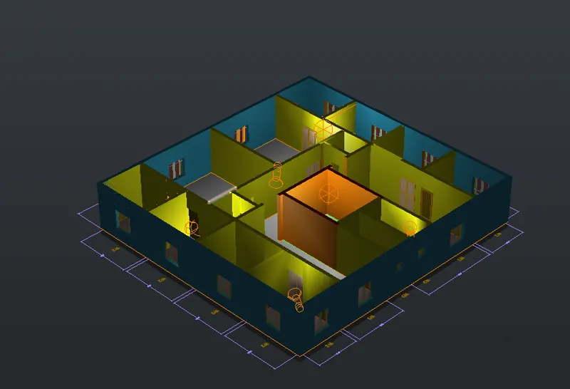
Step 12) Create a Chajja's
i) Chnage the view to 2D wireframe
ii) Command UCS - Select Object
iii) Draw the rectangle over the window
iv) Extrude the rectangle at a distance 400mm .
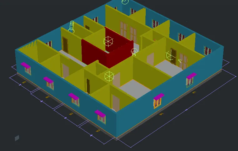
Step 13) Adding roof
i) Copy the plinth line which we have created earlier
ii) Copy the plinth line at a distance 3200mm
iii) Extrude the polyline at adistance of 200mm ( Ground floor top slab )
iv) Copy the ground floor plan at 1st floor
v) Similarly follow the same procedure till 3rd floor .
vi) Make sure that every time when you copied the plan do not take floor level .
vii) Assign the materials to the roof .
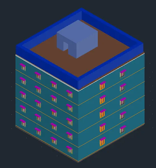
viii) At the roof create a door opening .
Step 14) Render View
i) After completion of all the steps , last step is render view
ii) For that Camera is placed around whole building
iii) . Select Image base lightining - Village
iv) Command Render - Rendering is done with following view .
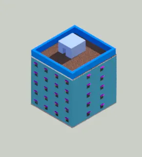
Following are the Cameras view
1)
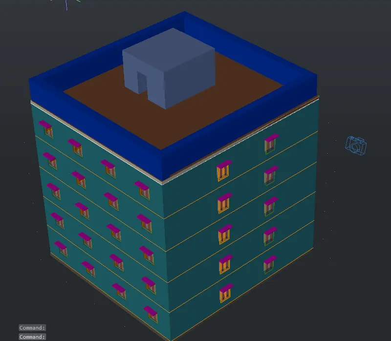
2)
3)
RESULTS -
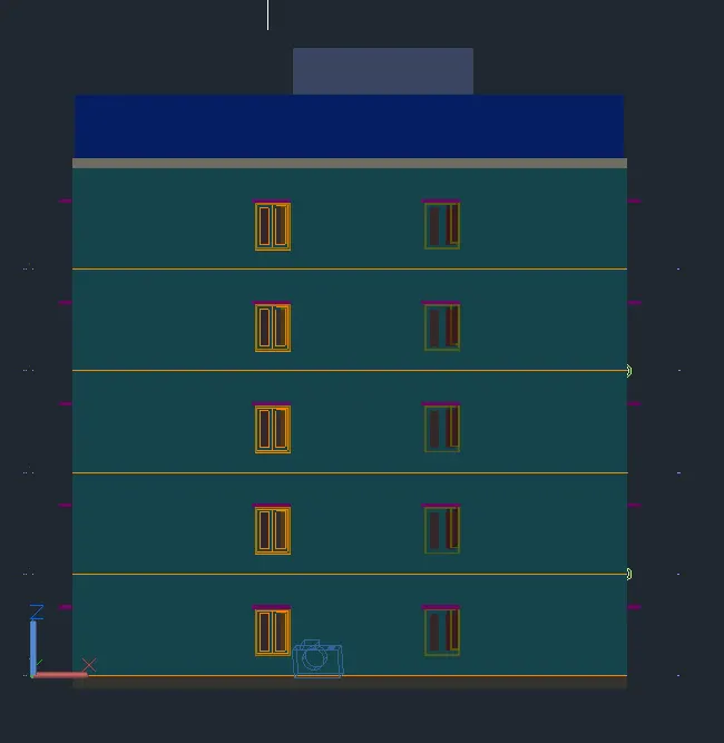
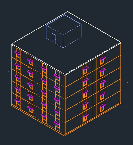
1) A 3D dimensional model view of Residential Building is create with four flats per floor.
2) G+4 building is model in 3D autocad
3) Dimensions are assume as per standard
4) Following are the views
A) 2D Plan layout
B) A view after converting 2D model into 3D model
C) A view after assigning the all the layers and material properties
D ) Hidden View of Entire Building
E) Cross Section of Dog-Legged Staircase
F) Render view of the Building .