Project 2_Creating a 3D rendered model for a Residential Building in AutoCad
1.Aim & Introduction
Aim
This challenge aims to let the student utilize the tools in Autocad to create a 3D sketch. It aims to help the student familiarize with thedifferent 3D commands present in the AutoCAD software. This challenge aims to correlate the 2D drawing into 3D sketches
Introduction
The AutoCAD software provides different tools. used in this challenge is as described below:
Line- creates line object
Polyline- creates rectangle line object
Rectangle- creates rectangles object
Circle- create circle object
Trim-Cut unwanted lines or shapes with the provided cutting edges
Extended- Extend lines to opposite corners
Move- Move objects to particular locations
Copy- Copy obejects to particular locations
Rotate- Rotate selected objects to a particular angle with respect to base point
Array- Copy an object in a set path linearly or polarly
Join- Joins separated line objects to a particular angle with respect to base point
Dimlinear(DLI)- provides vertical or horizontal linear/ straight dimensions
Dimligned(DAL)- Provides dimensions with respect to the angle of the object
Dimangular(DAN)- Provides angular dimensions between two line objects.
Quicklinedimension(QDIM)-provides quick dimension of a geometry
Leader- creates an arrow head line
Layer- Provides identification of line or object groups by their properties
Units- Open "Drawings Units" window to specify to modify the dimension properties
Hatch- provides hatching pattern in a given object or internal point
3D orbit- allows panning in the 3D view
Extrude- Creates a 3D solid, surfaces, or 2D regions by subtraction
UCS- Manages defined user corodinate systems
Union-Unions two solid or two region objects
2. Sketch and procedure:
A. Create a 3D model of the residential building with a rendered view
Procedure:
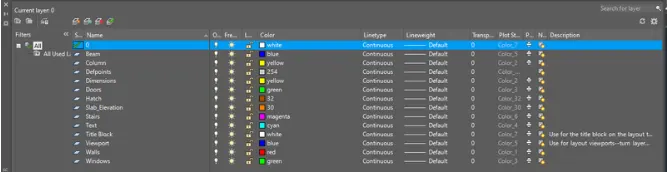
-----> Decide the layers
- These layers can be adjusted later as per requirement. Use the layer command
-----> Proceed with the plan drawing
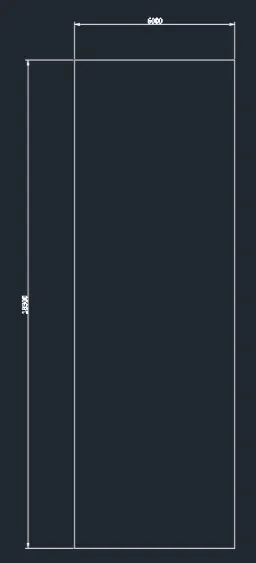
- Create boundary using object. Dimension 6m by 18.3m
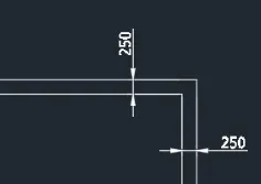
- Offset it by 250 towards the inside to project the wall. Add the plant north facing east
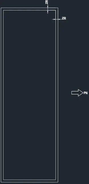
- Now create a projected boundaries for the layout. Add lines and use the extend/trim command to sketch the plan
- Start the top, position stairs in the middle
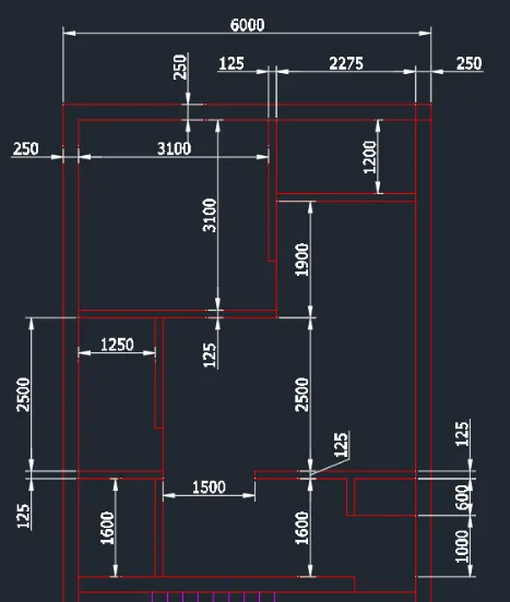
- Use line and trim tool to add the wall openings and trim the unnecessary lines
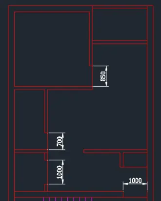
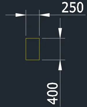
- Add the columns. Column size is 250x400mm
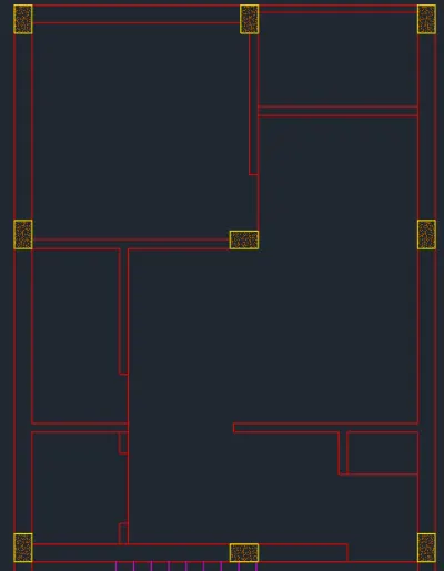
- Add the doors and windows at locations where it is needed
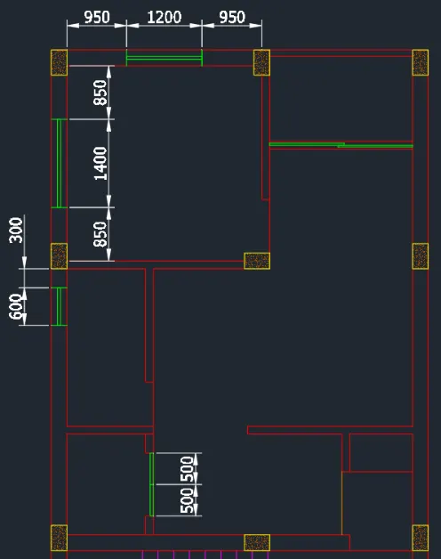
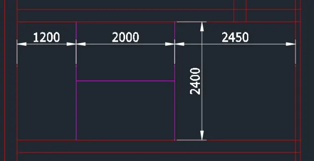
- Create the stair provosion at the middle part
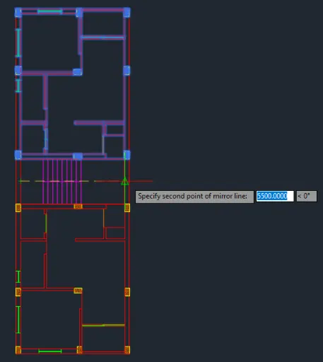
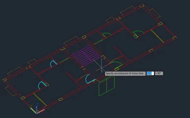
- Mirror the layout of the top room and mirror it on the other side. include the column walls, windows and door to the other side
- Add the door sysmbol
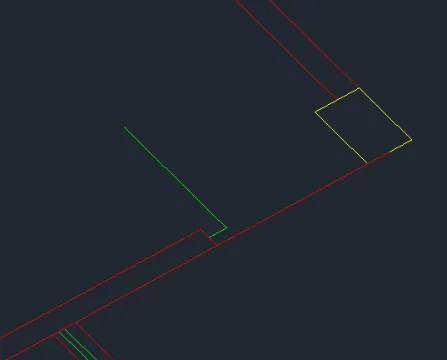
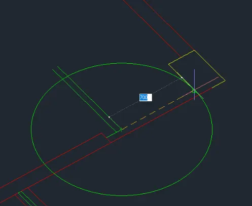
- Trim and close the edges
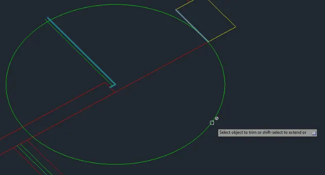
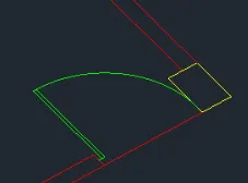
- Copy the door sysmbol to the doors
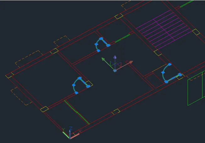
- Mirror to the other side
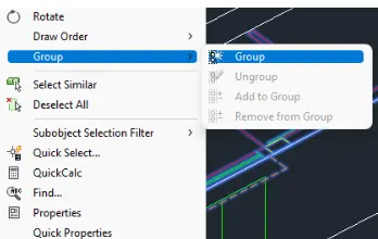
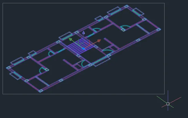
- Turn the plan into a group
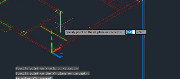
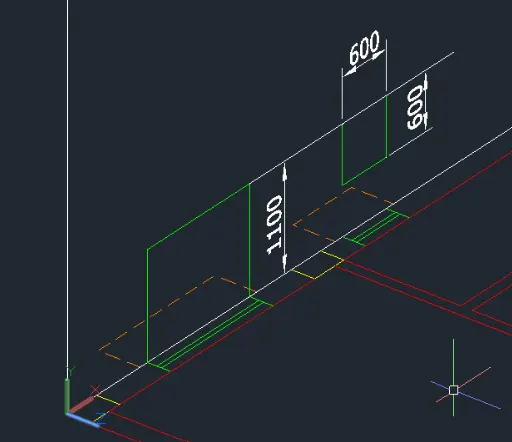
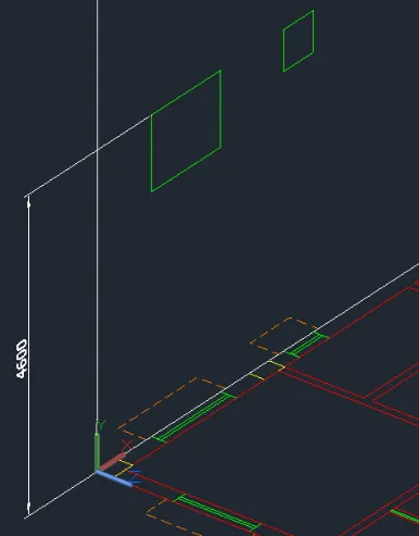
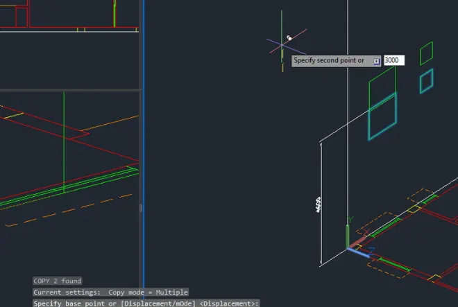
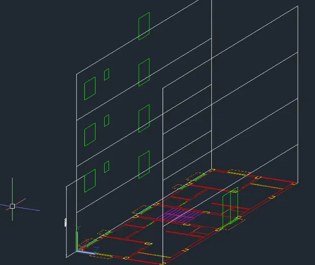
----->Create the front and side elevation of the drawing in the front view
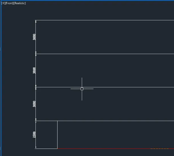
- Add the window and door locations
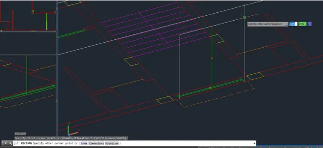
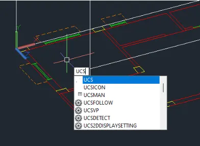
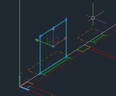
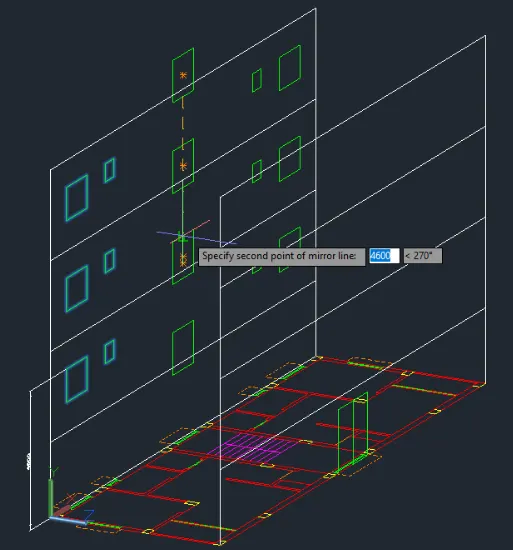
---> Proceed to extrusion of columns. Move elevation to the second floor
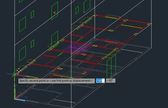
- Turn off the other layers to avoid selecting them
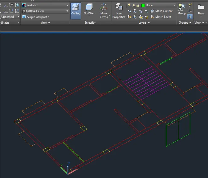
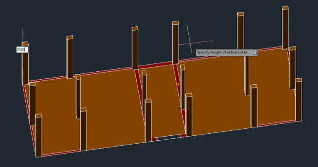
- Extrude the columns. Isolate the column layer to avoid selecting the others
- Move the columns to the bottom
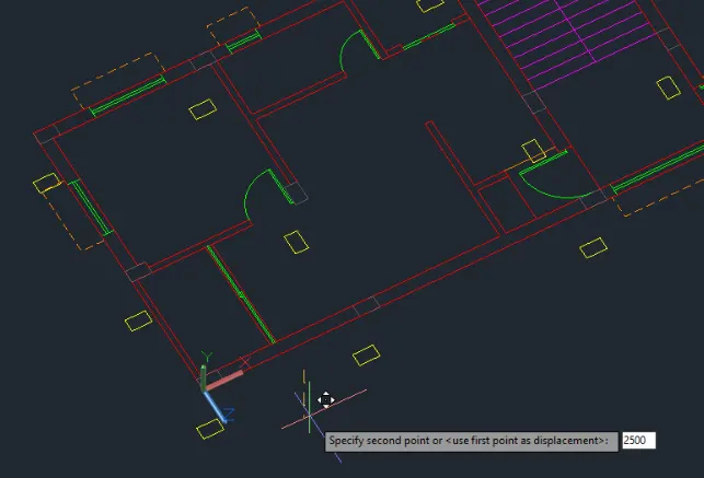
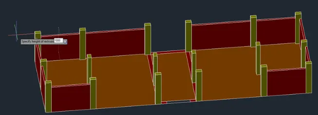
- Extrude to the structure height
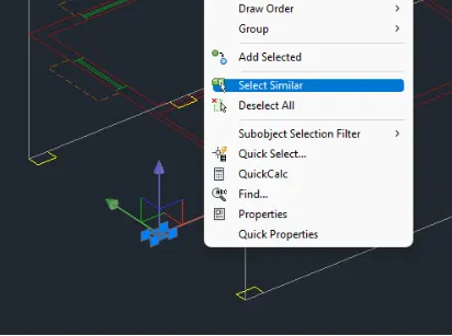
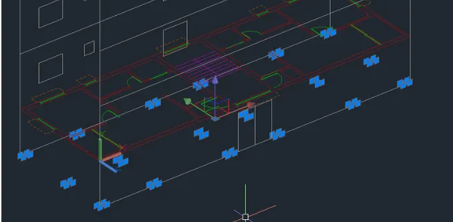
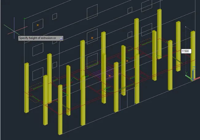
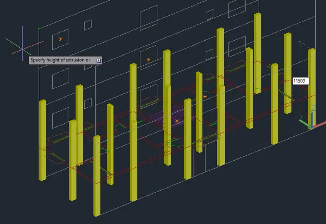
- Turn on all the laures and proceed with the walls on the 2nd floor
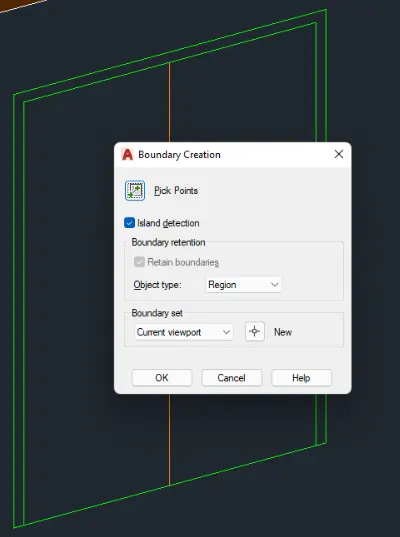
- Create regions for extrusions
- Turn off unnecessary layers
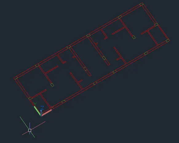
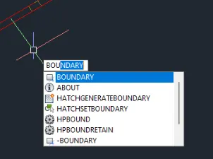
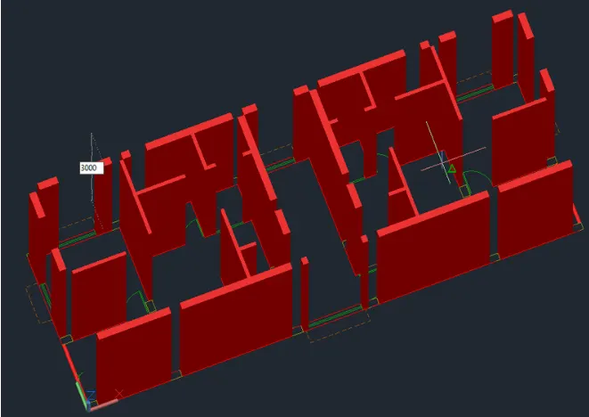
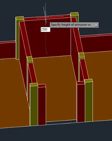
- Create the opening
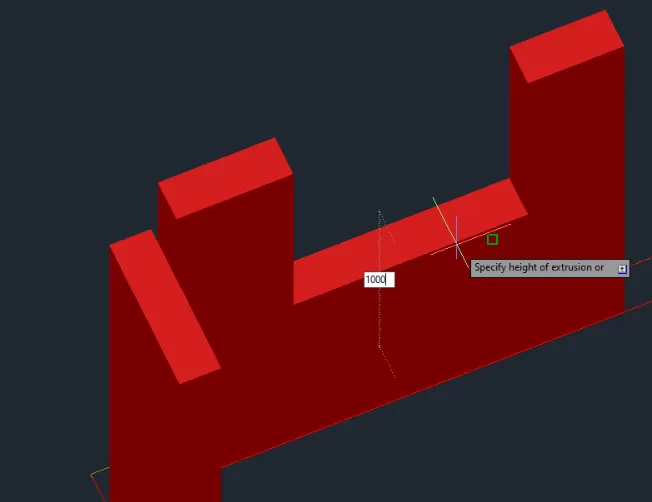
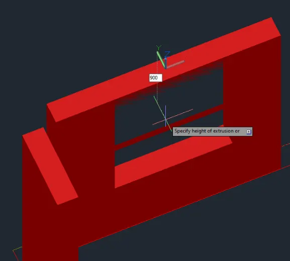
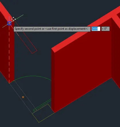
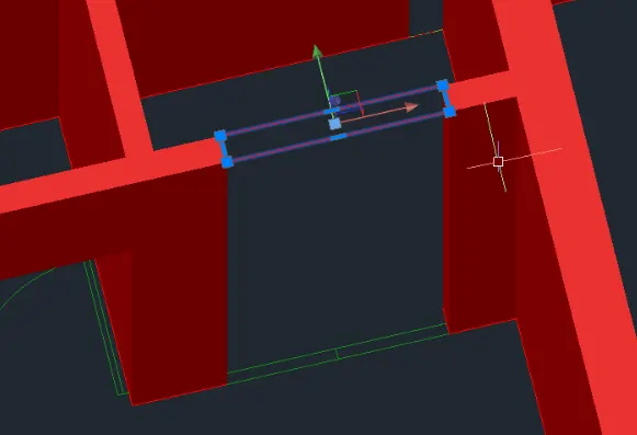
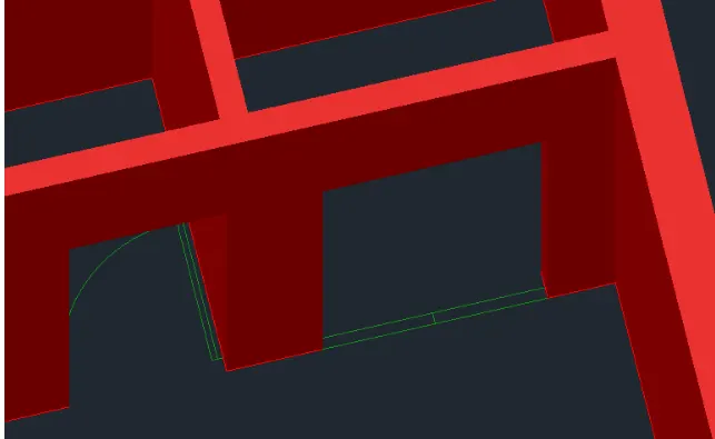
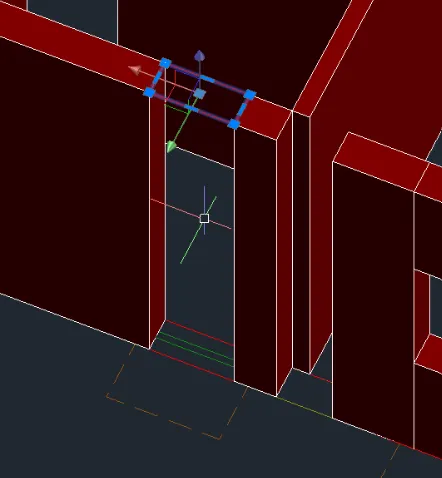
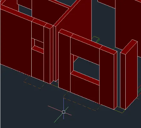
- Copy the opening edges to the other side mirror is also applicable
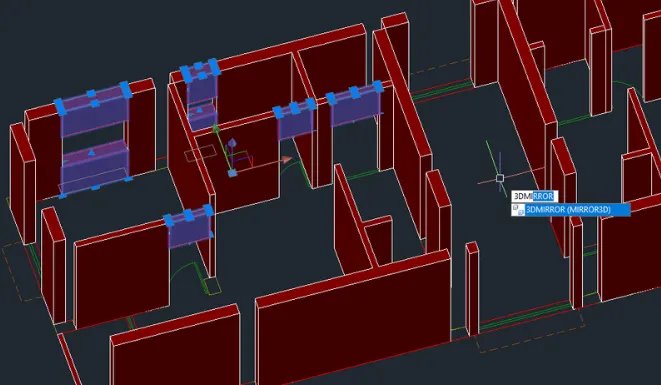
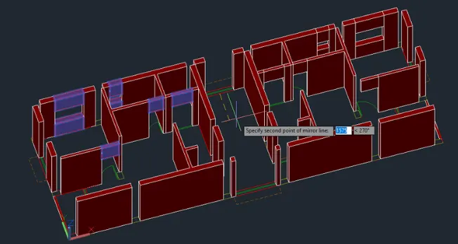
- Create the opening for the stair
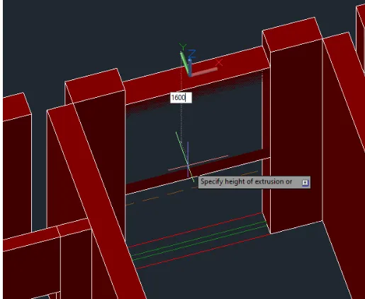
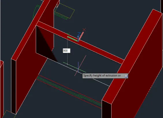
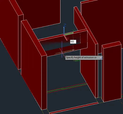
- Join the 3D solids using union
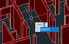
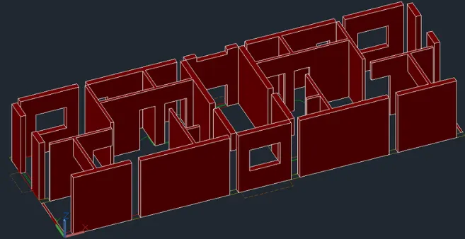
- Proceed with the balcony
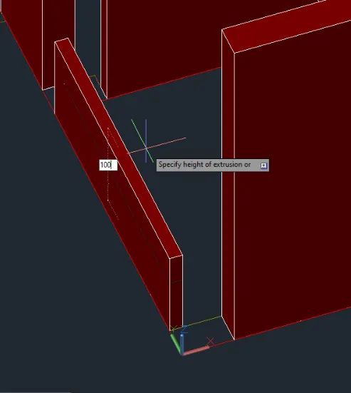
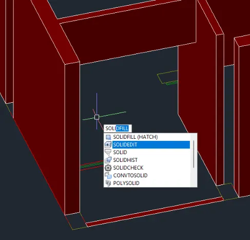
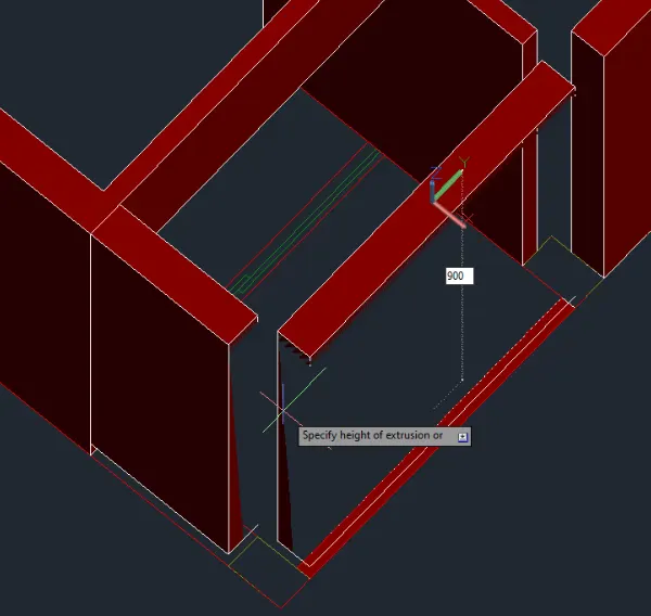
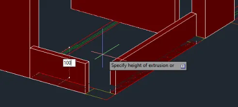
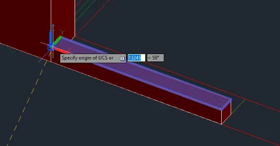
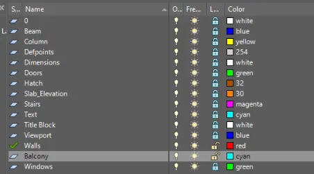
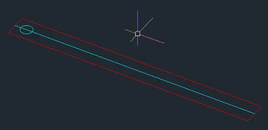
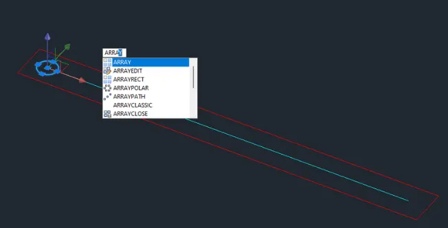
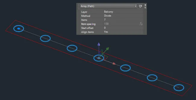
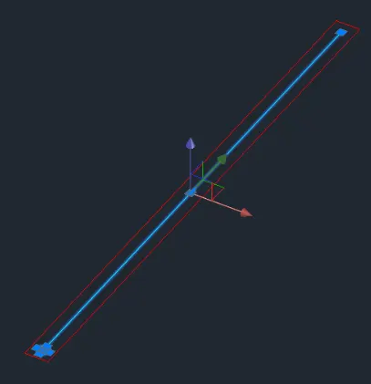
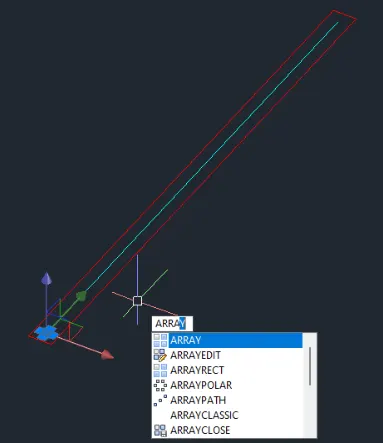
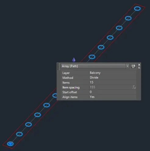
- Explode the array for extrusion
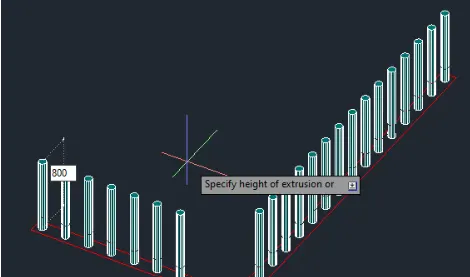
- Add the line on top
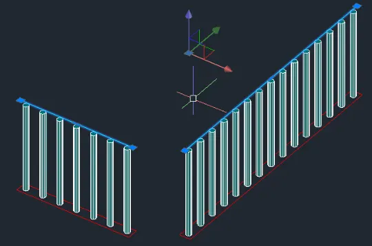
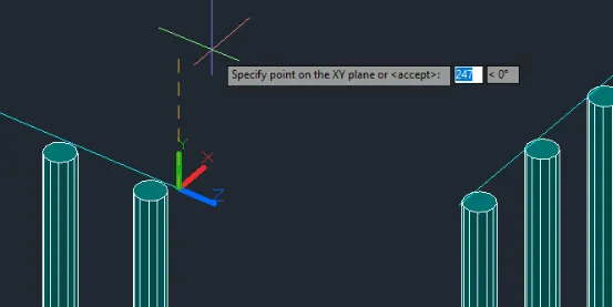
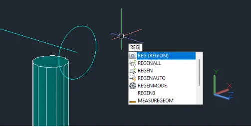
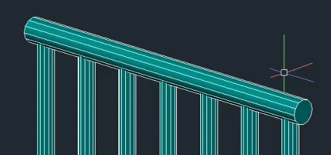
- Do the same on the other side
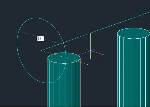
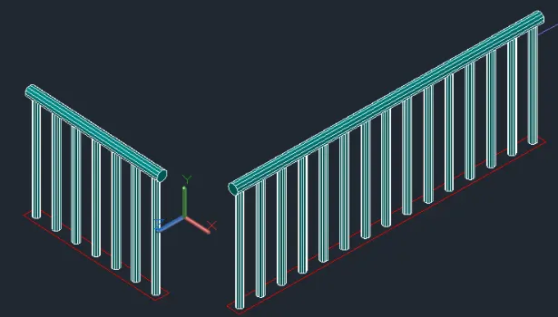
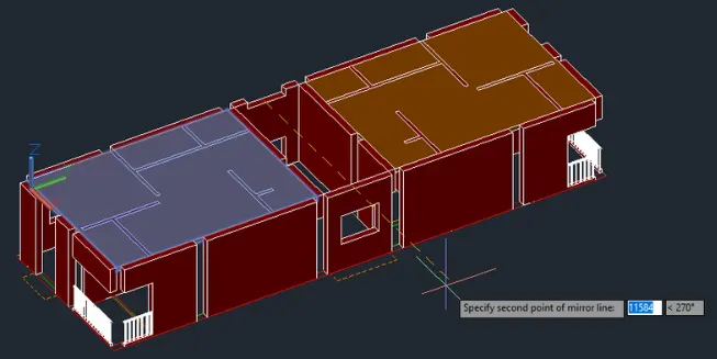
- Mirror to the other side of the building
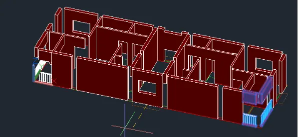
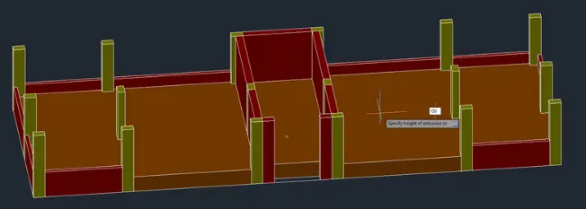
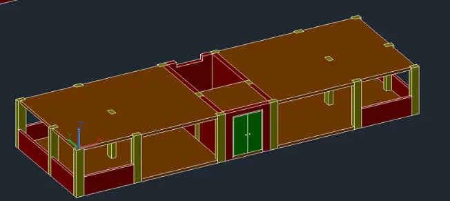
- Add the slabs
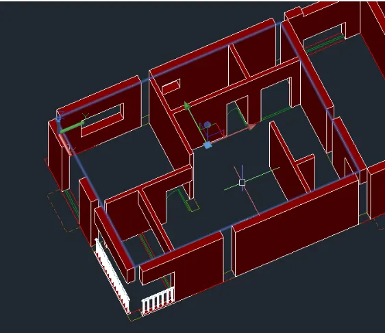
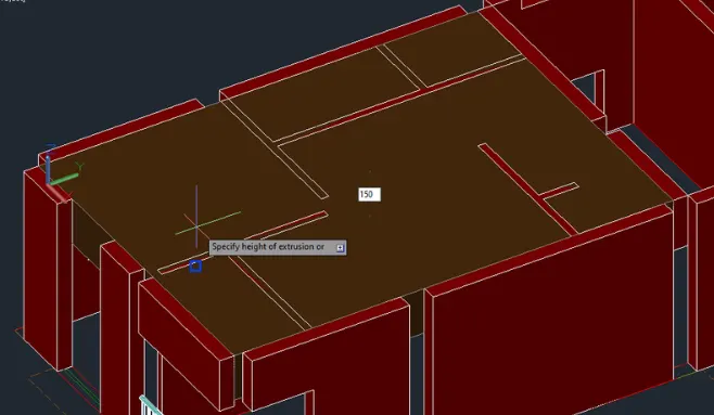
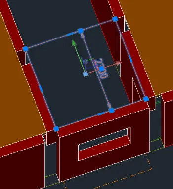
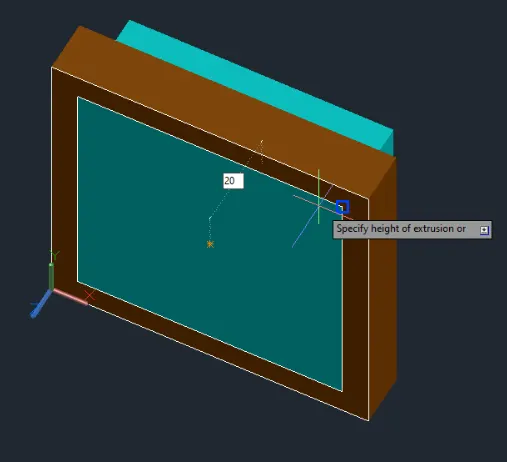
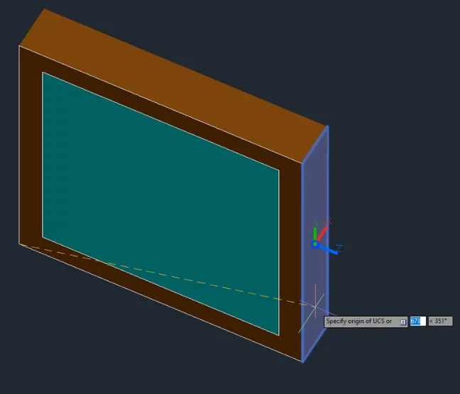
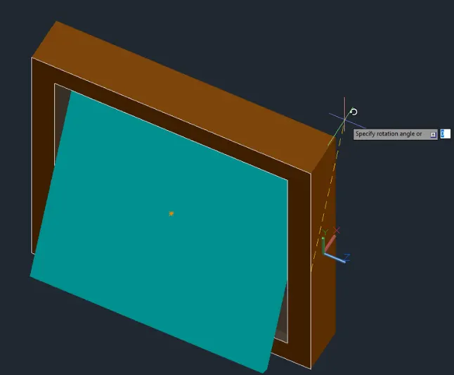
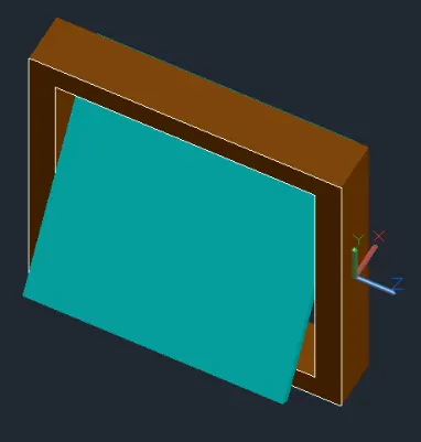
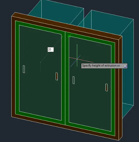
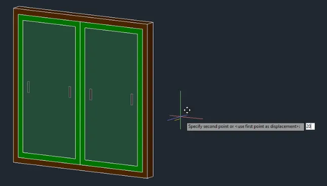
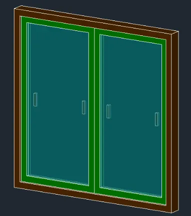
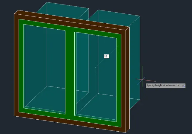
- Create the door and window faces
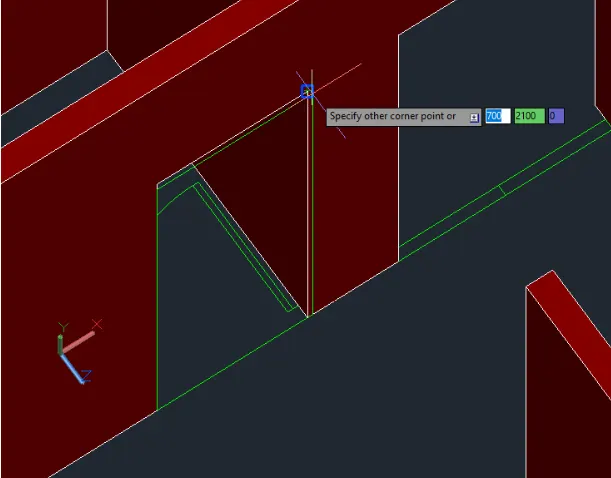
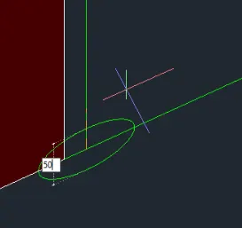
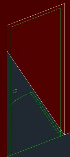
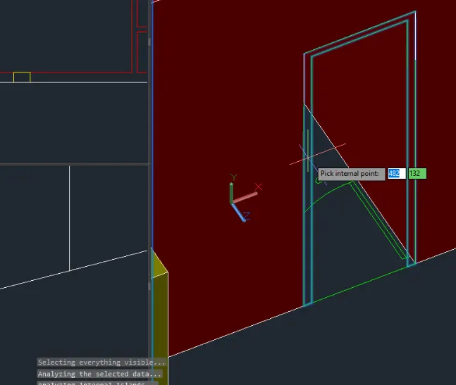
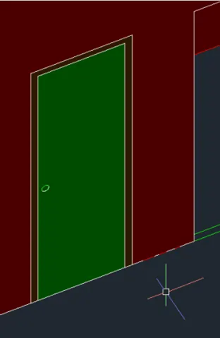
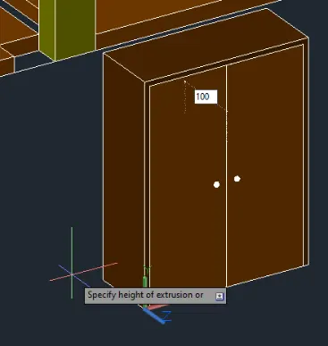
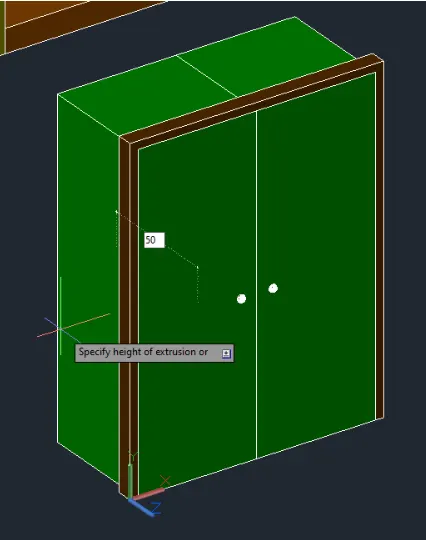
- Extrude for solidity
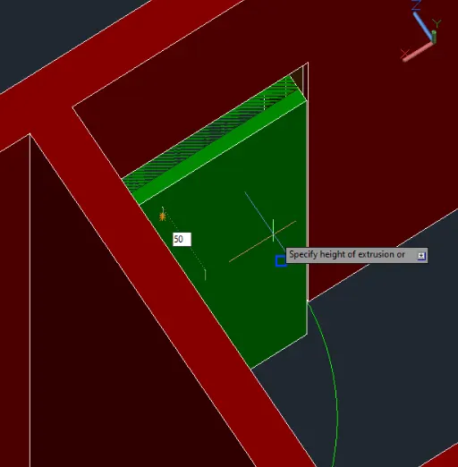
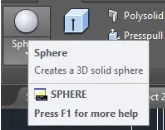
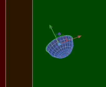
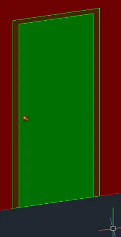
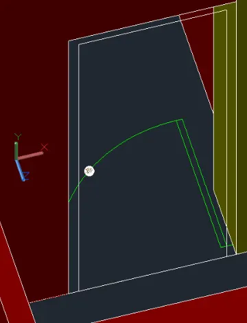
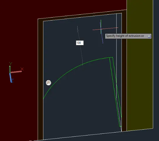
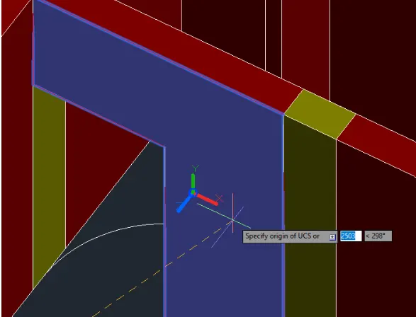
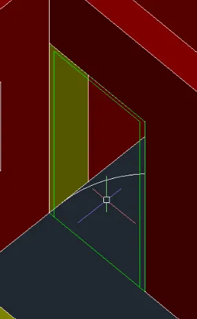
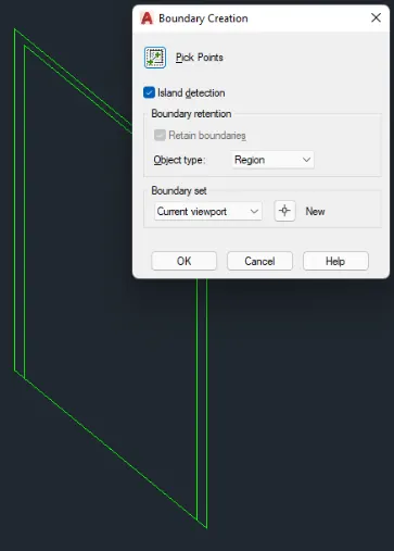
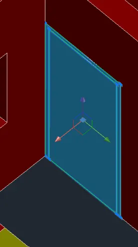
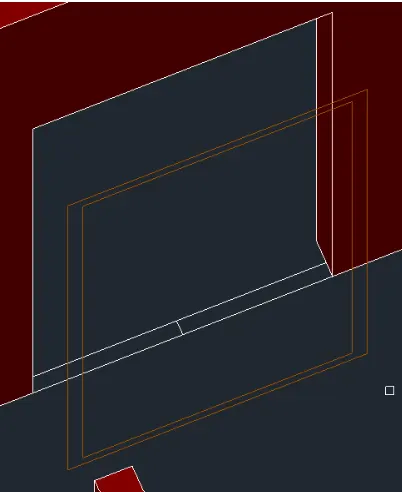
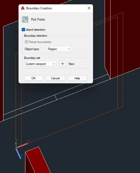
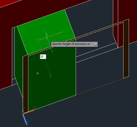
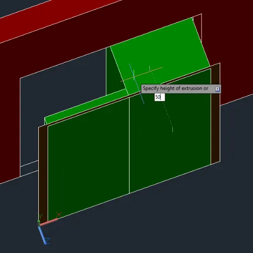
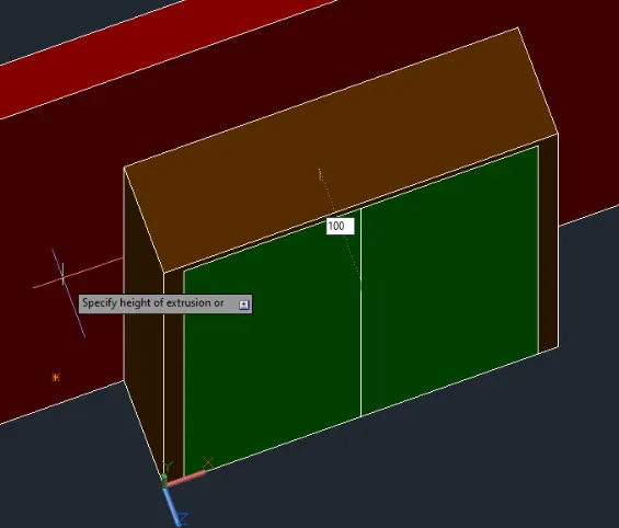
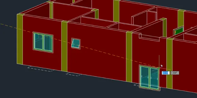
- Mirror the other side
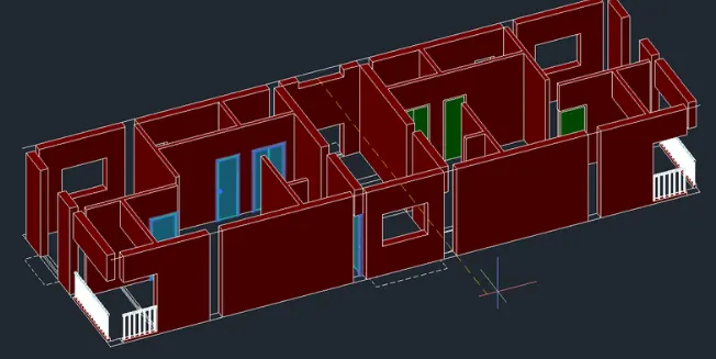
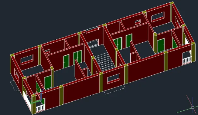
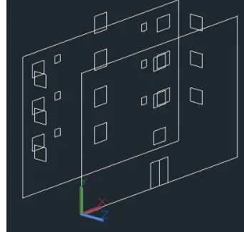
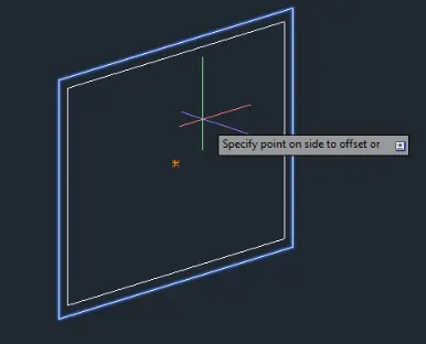
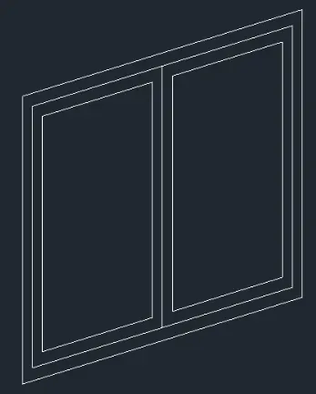
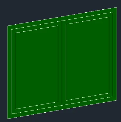
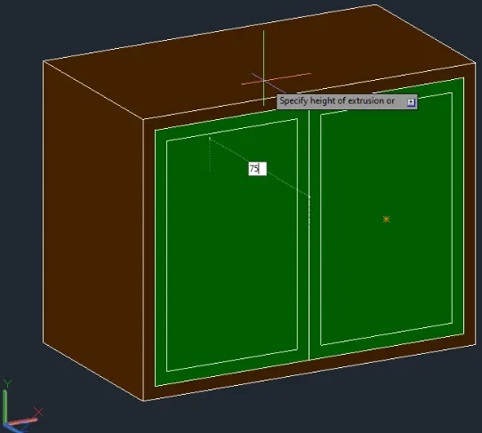
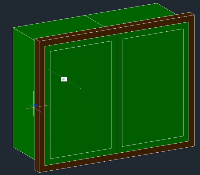
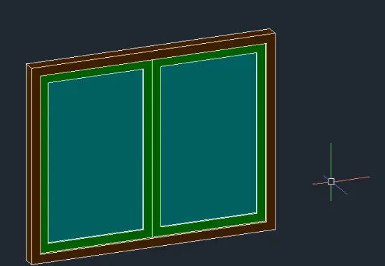
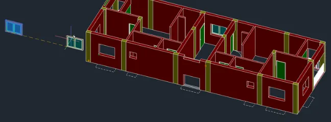
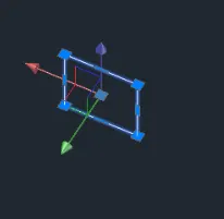
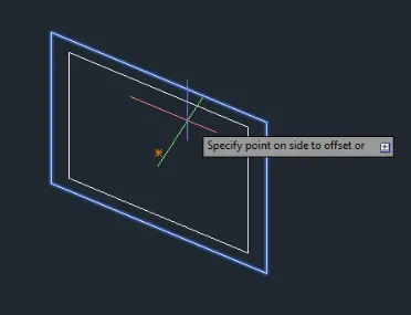
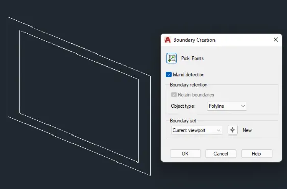
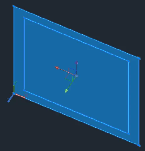
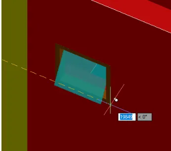
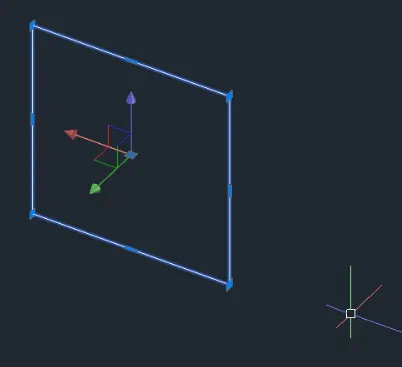
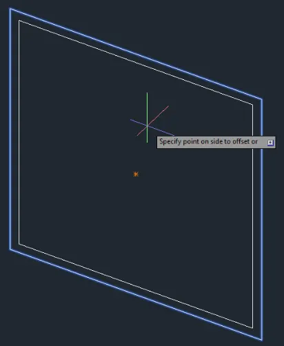
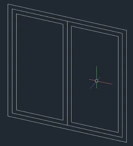
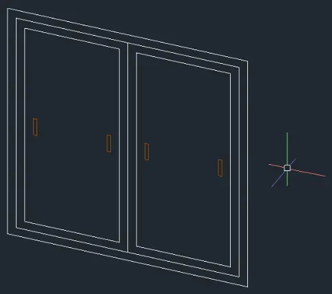
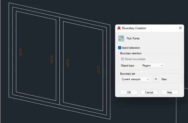
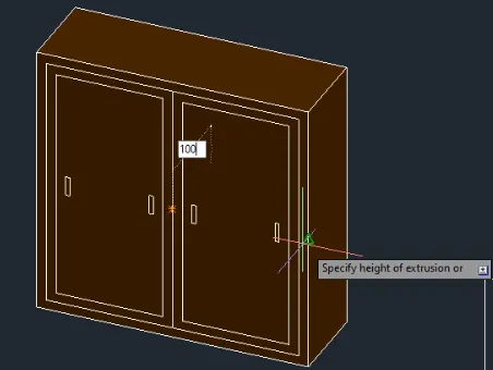
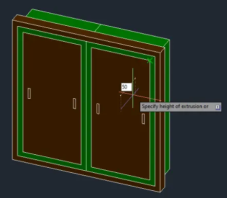
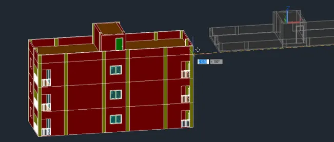
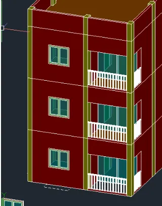
- Once the first floor is done, copy it to duplicate the floors
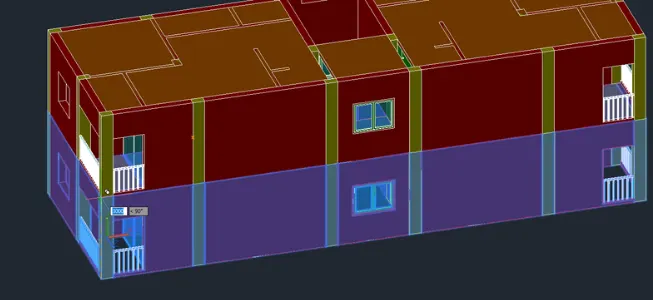
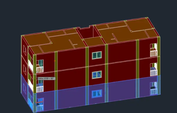
- Create the balcony
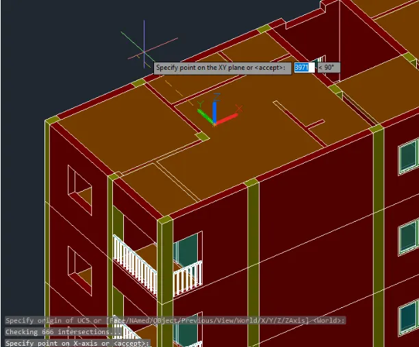
- Separate the line for better view
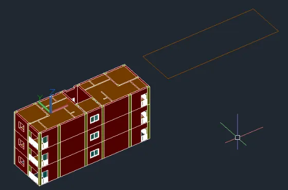
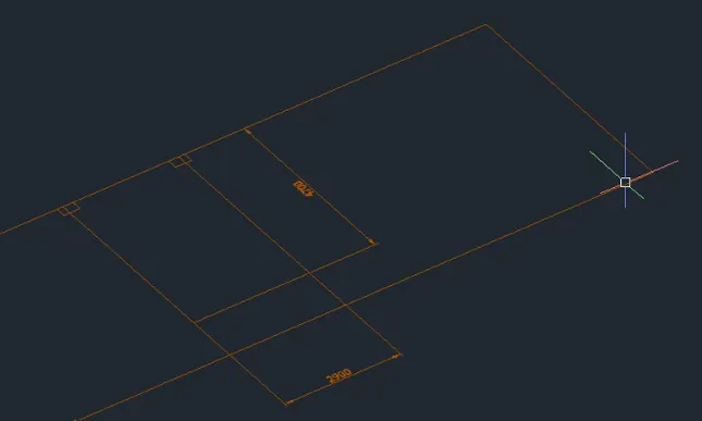
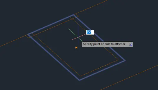
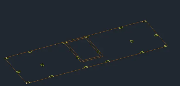
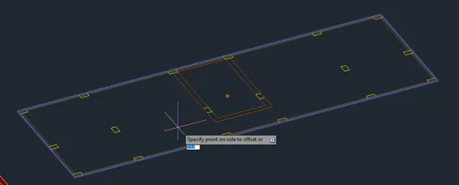
- Add the boundaries for extrusion
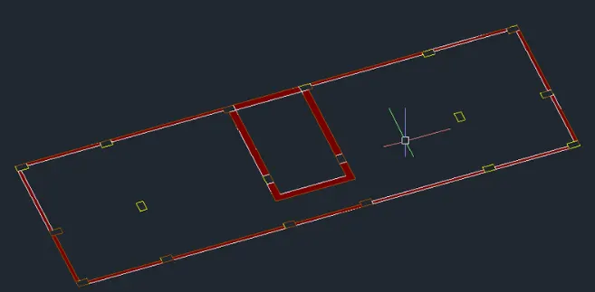

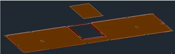
- Extrude to specificified height
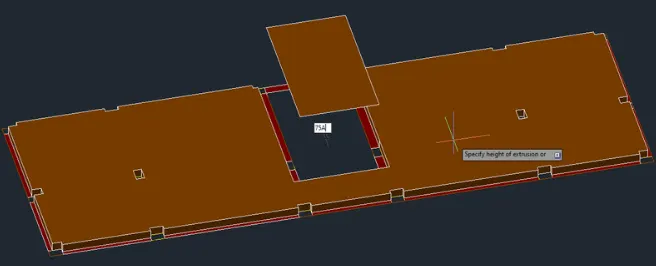
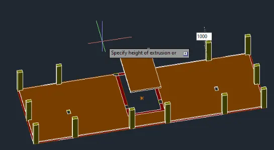
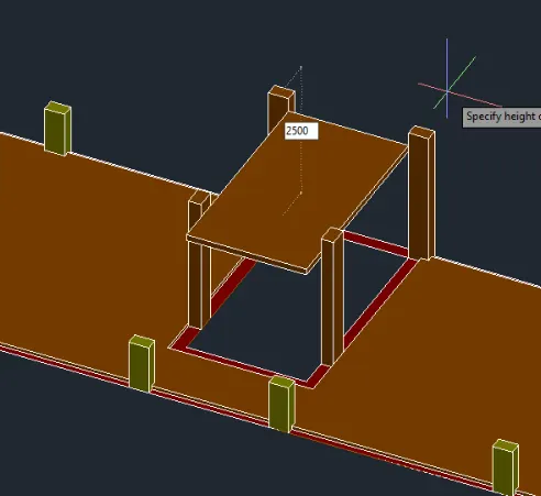
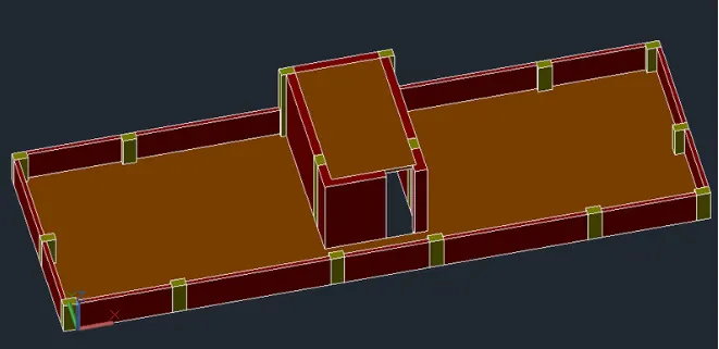
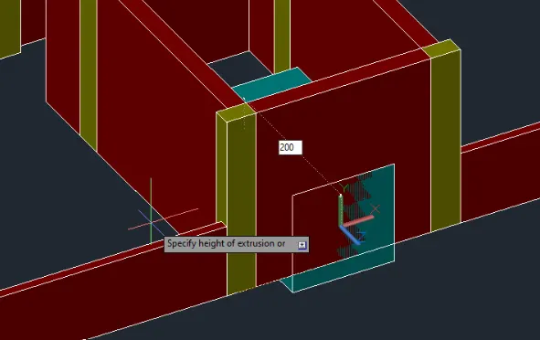
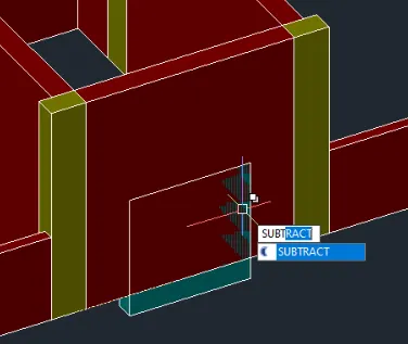
- Create the missing windows then proceed to the first floor
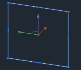
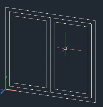
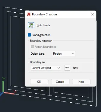
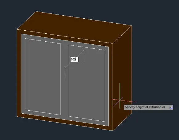
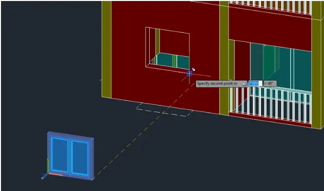
- Proceed with the 1st floor plan
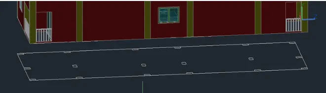
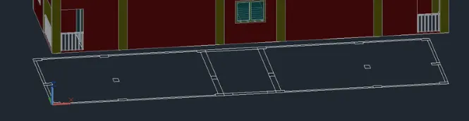
- Add the regions
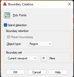
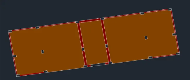
- Extrude and join with the solids
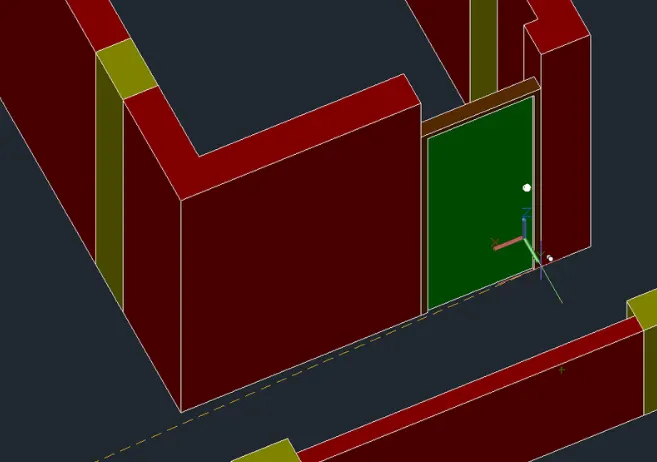
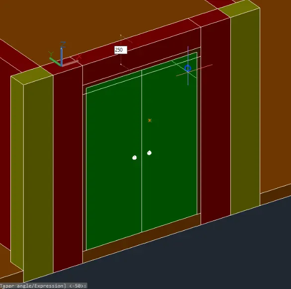
- Add the door
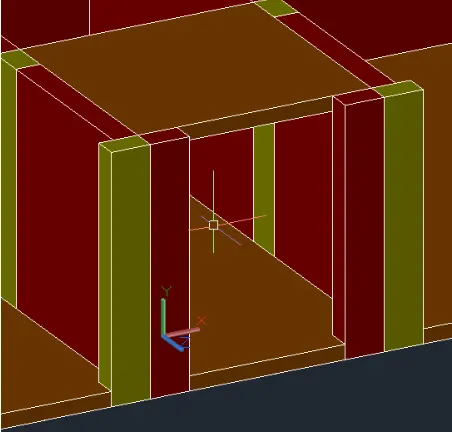
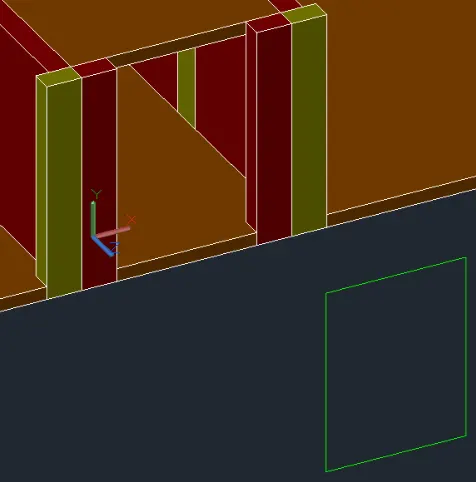
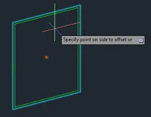
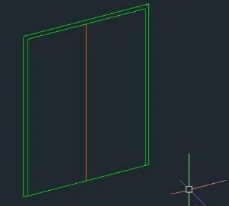
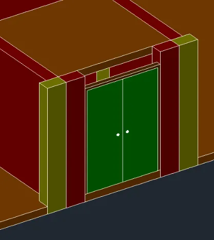
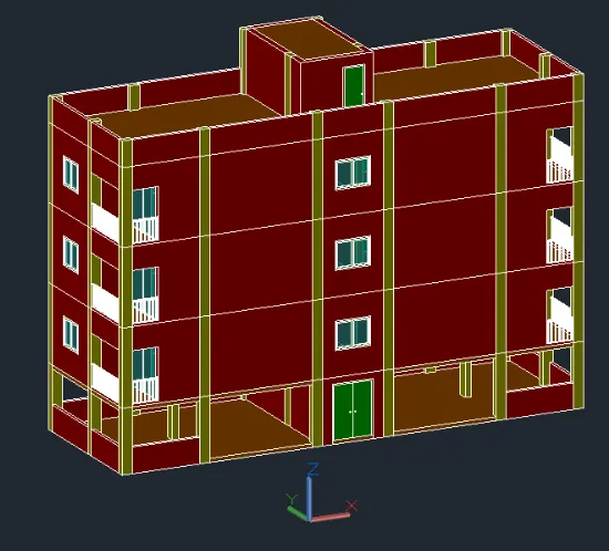
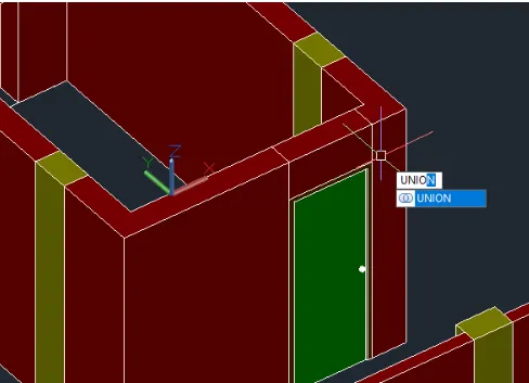
- Union the available solids
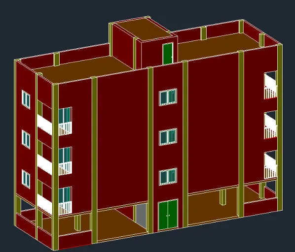
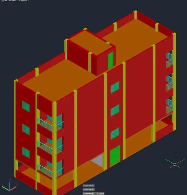
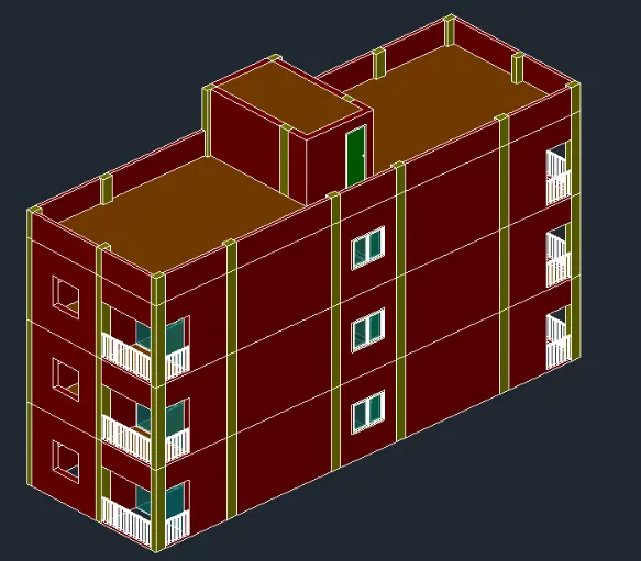
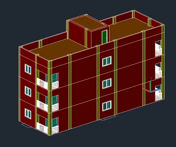
- Add materials
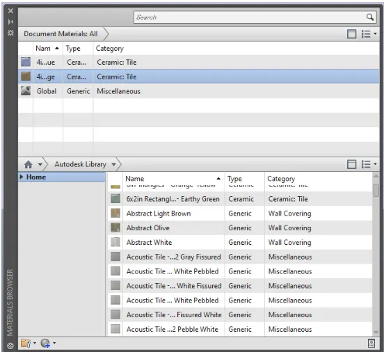
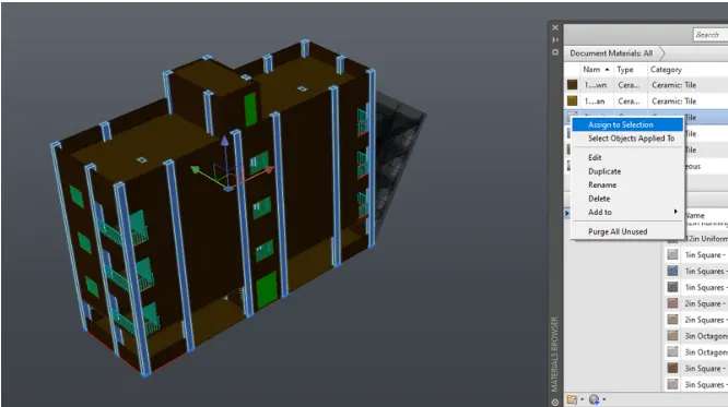
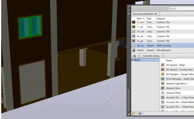
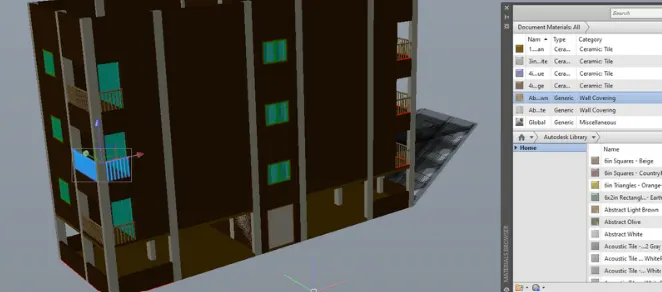
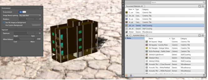
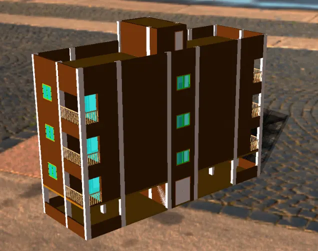
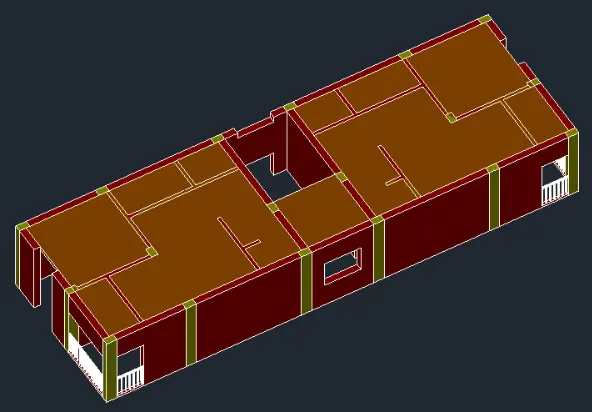
Result:
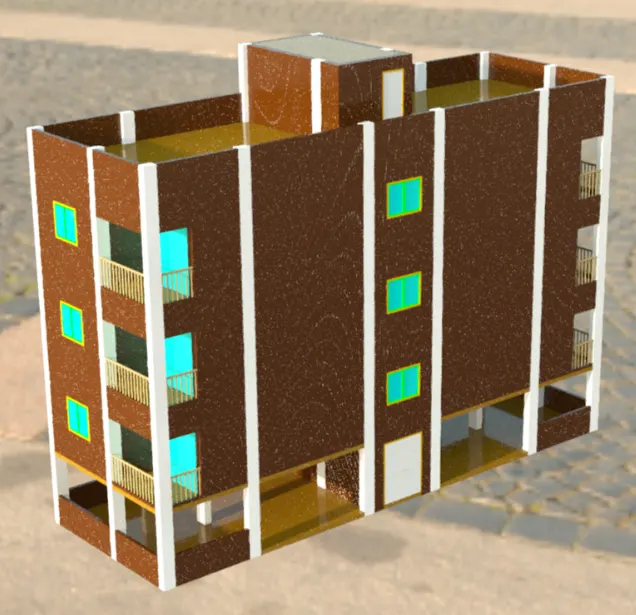
3.Conclusion
The AutoCAD software allows 3D sketches where solid objects or 3D surfaces are present. By using 3D function of the AutoCAD software, one can illustarte or convert a 2D sketch into a 3D illustartion
1.Aim & Introduction
Aim
This challenge aims to let the student utilize the tools in Autocad to create a 3D sketch. It aims to help the student familiarize with thedifferent 3D commands present in the AutoCAD software. This challenge aims to correlate the 2D drawing into 3D sketches
Introduction
The AutoCAD software provides different tools. used in this challenge is as described below:
Line- creates line object
Polyline- creates rectangle line object
Rectangle- creates rectangles object
Circle- create circle object
Trim-Cut unwanted lines or shapes with the provided cutting edges
Extended- Extend lines to opposite corners
Move- Move objects to particular locations
Copy- Copy obejects to particular locations
Rotate- Rotate selected objects to a particular angle with respect to base point
Array- Copy an object in a set path linearly or polarly
Join- Joins separated line objects to a particular angle with respect to base point
Dimlinear(DLI)- provides vertical or horizontal linear/ straight dimensions
Dimligned(DAL)- Provides dimensions with respect to the angle of the object
Dimangular(DAN)- Provides angular dimensions between two line objects.
Quicklinedimension(QDIM)-provides quick dimension of a geometry
Leader- creates an arrow head line
Layer- Provides identification of line or object groups by their properties
Units- Open "Drawings Units" window to specify to modify the dimension properties
Hatch- provides hatching pattern in a given object or internal point
3D orbit- allows panning in the 3D view
Extrude- Creates a 3D solid, surfaces, or 2D regions by subtraction
UCS- Manages defined user corodinate systems
Union-Unions two solid or two region objects
2. Sketch and procedure:
A. Create a 3D model of the residential building with a rendered view
Procedure:
-----> Decide the layers
- These layers can be adjusted later as per requirement. Use the layer command
-----> Proceed with the plan drawing
- Create boundary using object. Dimension 6m by 18.3m
- Offset it by 250 towards the inside to project the wall. Add the plant north facing east
- Now create a projected boundaries for the layout. Add lines and use the extend/trim command to sketch the plan
- Start the top, position stairs in the middle
- Use line and trim tool to add the wall openings and trim the unnecessary lines
- Add the columns. Column size is 250x400mm
- Add the doors and windows at locations where it is needed
- Create the stair provosion at the middle part
- Mirror the layout of the top room and mirror it on the other side. include the column walls, windows and door to the other side
- Add the door sysmbol
- Trim and close the edges
- Copy the door sysmbol to the doors
- Mirror to the other side
- Turn the plan into a group
----->Create the front and side elevation of the drawing in the front view
- Add the window and door locations
---> Proceed to extrusion of columns. Move elevation to the second floor
- Turn off the other layers to avoid selecting them
- Extrude the columns. Isolate the column layer to avoid selecting the others
- Move the columns to the bottom
- Extrude to the structure height
- Turn on all the laures and proceed with the walls on the 2nd floor
- Create regions for extrusions
- Turn off unnecessary layers
- Create the opening
- Copy the opening edges to the other side mirror is also applicable
- Create the opening for the stair
- Join the 3D solids using union
- Proceed with the balcony
- Explode the array for extrusion
- Add the line on top
- Do the same on the other side
- Mirror to the other side of the building
- Add the slabs
- Create the door and window faces
- Extrude for solidity
- Mirror the other side
- Once the first floor is done, copy it to duplicate the floors
- Create the balcony
- Separate the line for better view
- Add the boundaries for extrusion
- Extrude to specificified height
- Create the missing windows then proceed to the first floor
- Proceed with the 1st floor plan
- Add the regions
- Extrude and join with the solids
- Add the door
- Union the available solids
- Add materials
Result:
3.Conclusion
The AutoCAD software allows 3D sketches where solid objects or 3D surfaces are present. By using 3D function of the AutoCAD software, one can illustarte or convert a 2D sketch into a 3D illustartion