Project 2_Creating a 3D rendered model for a Residential Building in AutoCad
- Create a 3 dimensional model of the residential building with a rendered view.
Aim :-
- To create the 3D model of residential building.
Introduction :-
- Autocad is mostly used for the 2D drawings.
- There is a wide range of pre-defined objects in the Autocad.
- There are some different commands wit hrespect to 2D drawingd.
- COmmands Used for creating the 3d model of building.
Extrude
Sweep
Union
Subtract
Intersect
Separate
Procedure :-
- Open the Autocad.
- Select 3D MOdelling.
- Enter the Un and change the units to Engineering.
- Select line command and select the top view to draw the plan.
- Draw the Xline in vertical direction.
- offset the line with 3' in left side.
- Offset the line of 8'6" in right side from main line.
- Now offset the lines with 9", 3'8.75", 5', 3'8.75", 9", 12'2.5", 10" in parallel direction.
- Now select the XLINE.
- And draw the lines horizontally with the offset of the 4'2" of the balcony in right corner.
- Now offset the lines with 6",11'3.5", 9", 16'2", 6", 4'10", and 9" at the right side.
- Offset the ines with the distance of 10", 7'0.75", 6', 7'6.75' and 3'.
- Now draw the lines of wall.
- And draw the plan.
- Draw the stairs outsid the building and inside the plot.
- Dra the lines respectively.
- Hatch the walls with HATCH command.
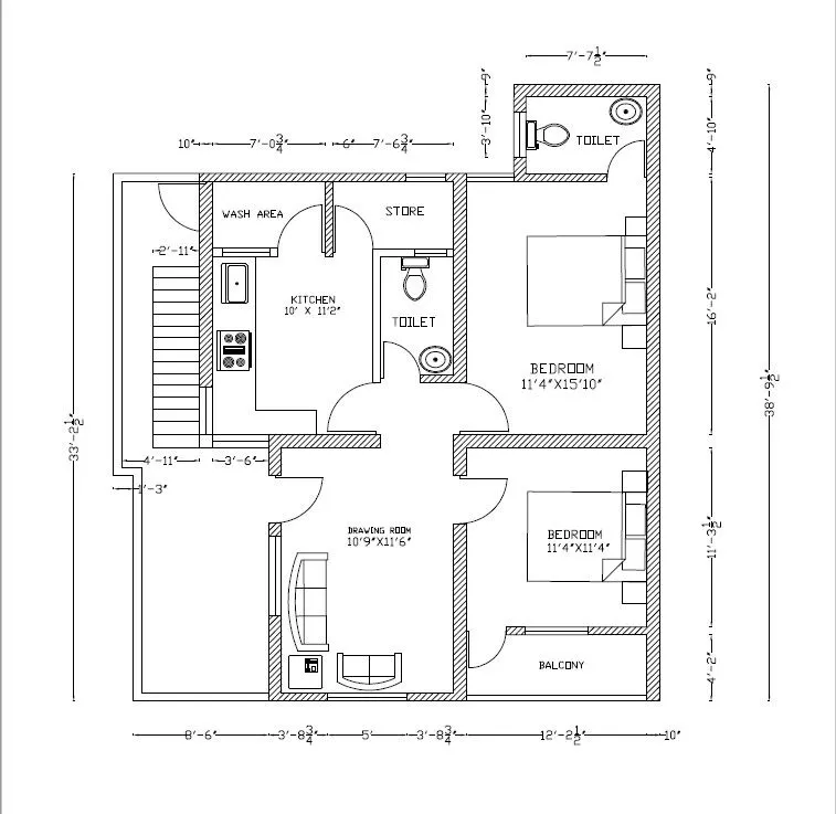
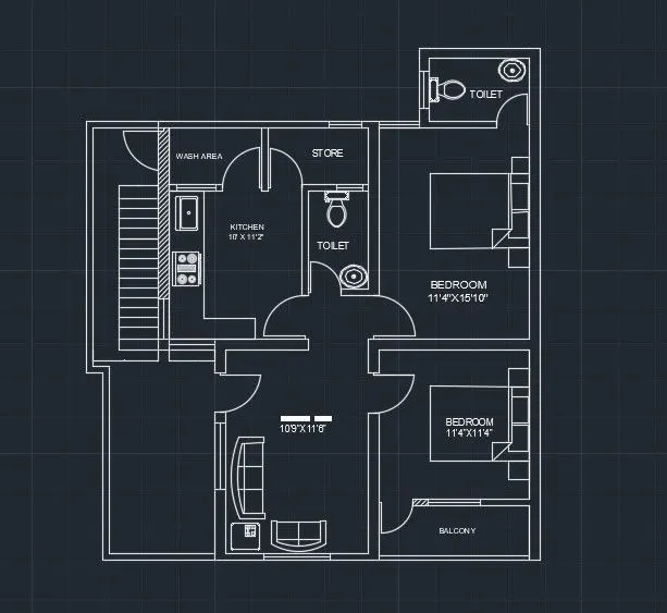
- Steps for creating the plan is as per following.
- Command boundary and select the region and CLick OK.
- So it will convert in one boundary.
- Extrude the regions that are cinverted into boundaries.
- Extrude the lines wit hthe height of 10'.
- Create the different layers for the different component.
- Assign each colour to layers.
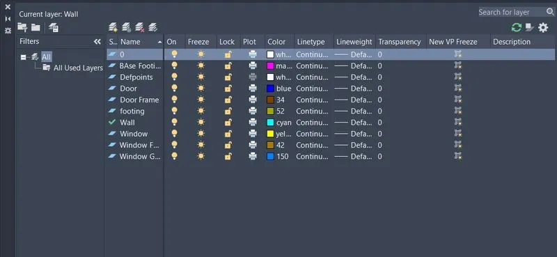
- Extrude the doors at the height of 7'.
- Extrude the windows at the height of 3'.
- Now do the same process for every door and window.
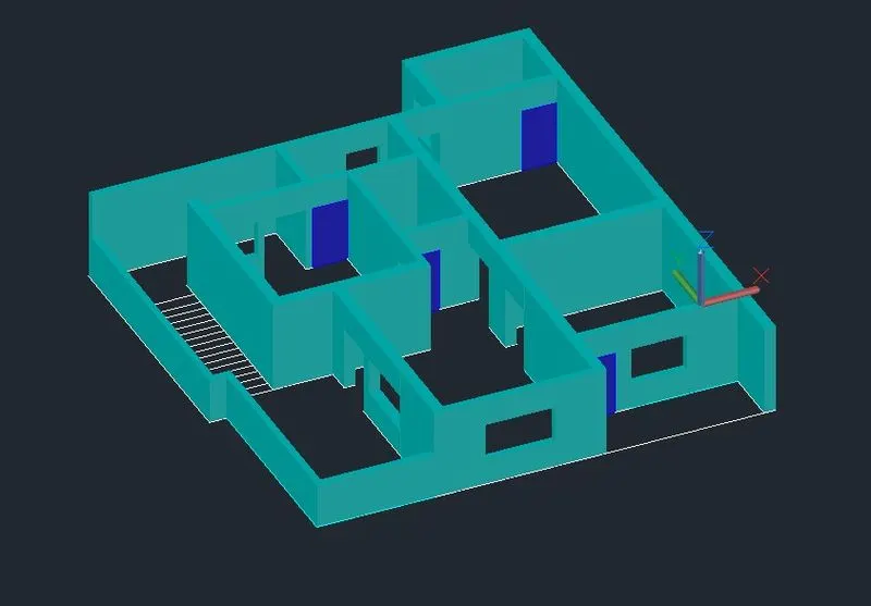
- Draw the verandah fancing with the height of 5'.
- Now insert the doors and windows at their suitable places.
- Insert the doors with the specific size.
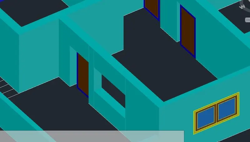
- Using the Polyline command, draw the lines at the outer body at flooring.
- Now Extrude that polyline with 2' forming the floor.
- Apply different layer to the flooring.
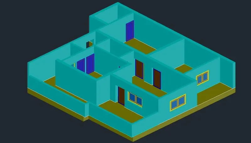
- Draw the plyline across the boundary of the building at the top side.
- Using extrude command, extrude the line with the 6" for the flooring.
- Select the entire building, From top to bottom till the plinth level and copy and paste it wi th distance of 10'.
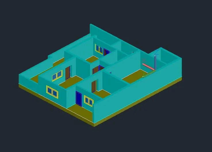
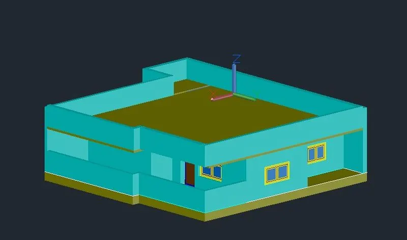
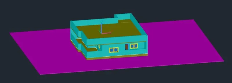
- Now draw the region outside the building area.
- And apply the different layer in that region.
- Now applying the sun and shadows in the drawing.
- For that go into visualize menu and select the sun and shadows.
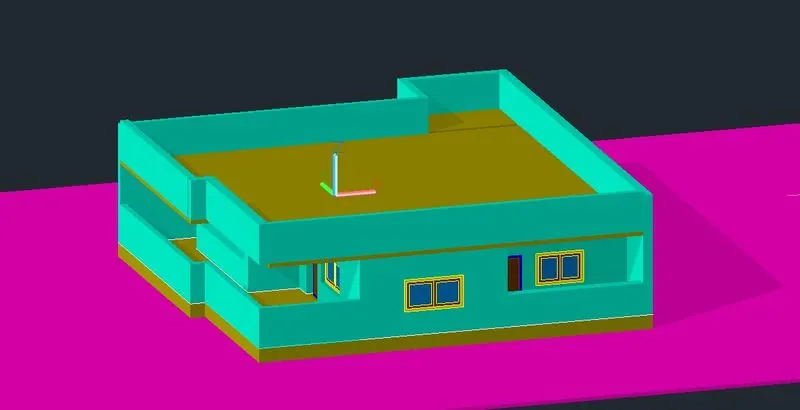
- Now apply the materials in the drawing.
- For that go into visualize menu and select the material browser.
- Add the material et the top.
- Then select the object and select the material in material browser and right click and apply the material.
- Selected materials are used in the drawing.
- List of Materials that are qapllied in the drawing is as per following.
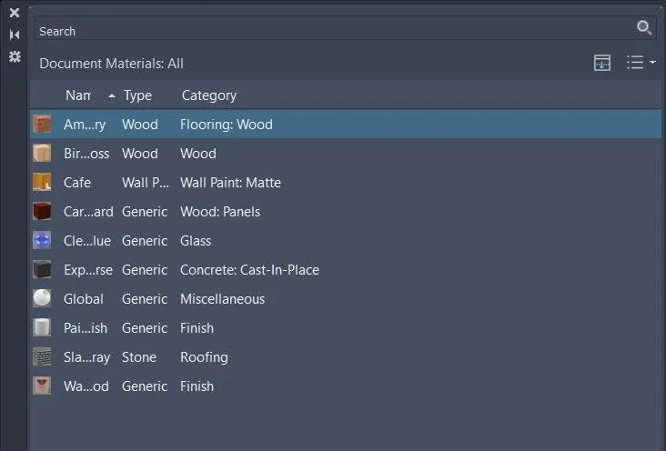
- These are the materials are apllied in the building.
- After effect of appling the materials is as per below.
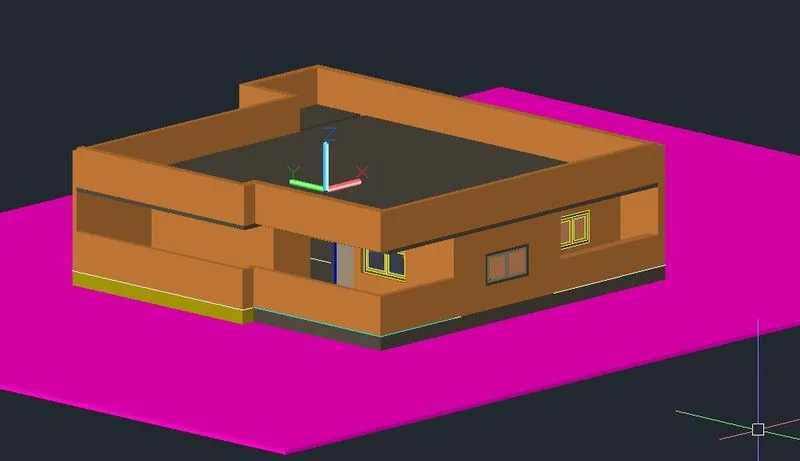
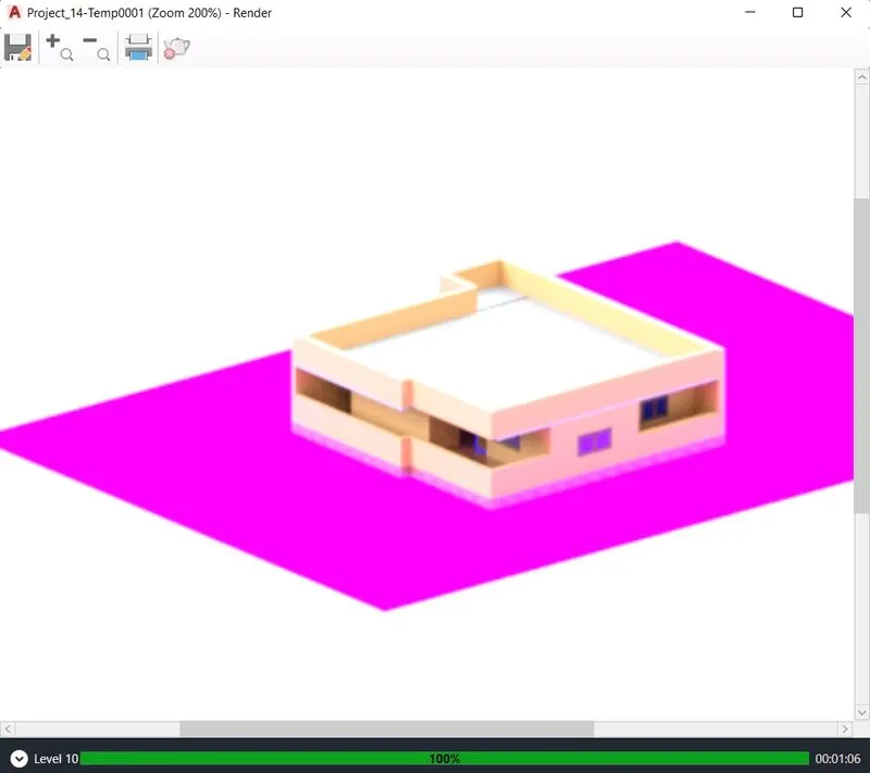
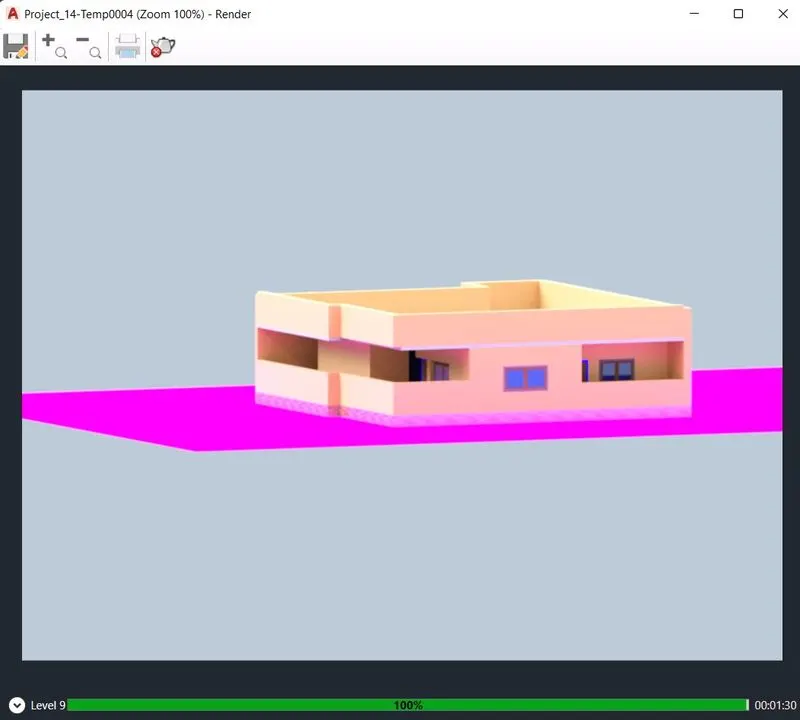
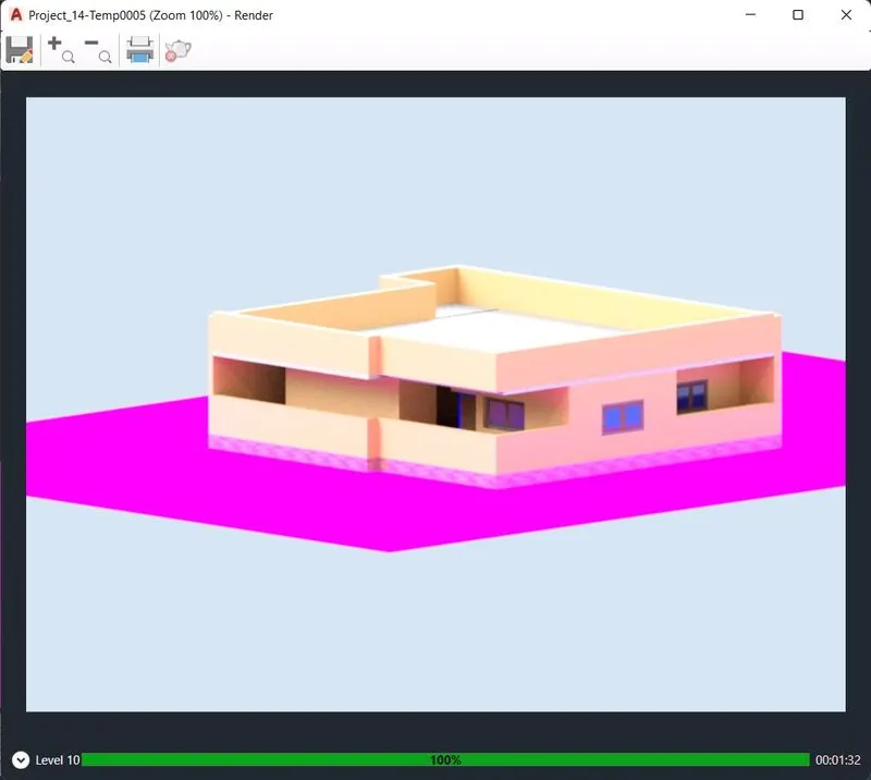
- Different view of the building is as per following.
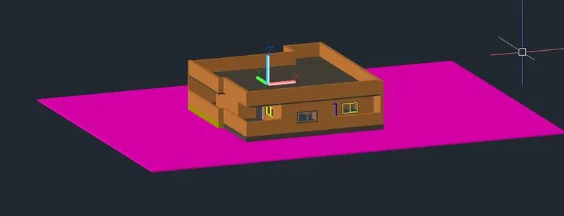
- Rendering at the dark shadow is done here.
- Go to visualize tab from ribbon.
- Create different views from camera and render the building.
Result :-
- Building as 3D model is created here.
- Then materials are applied in the building.
- Then drawing was rendered by different specifications.
Plan:-
Rendered Views :-