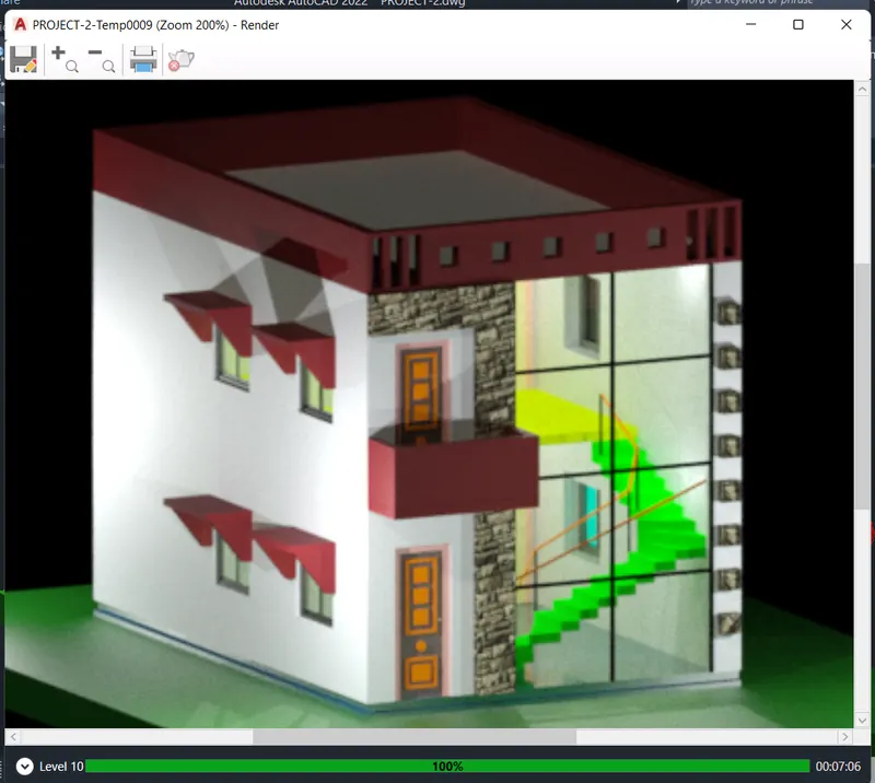
Project 2_Creating a 3D rendered model for a Residential Building in AutoCad
AIM
To create a 3-dimensional model of the residential building with a rendered view
INTRODUCTION:
- 3D computer-generated images of proposed building projects and other types of constructions are designers to showcase their designs to clients
- The steady advancement in computer graphics has enabled the creation of realistic 3D commercial rendering for building projects.
- Commercial rendering has become ubiquitous in the real estate market Both small and mega commercial companies want to see their future buildings 3D architectural renderings before giving the contracts to architects and builders.
COMMANDS USED
- Line command
- Rectangle command
- UCS command
- Dimlinear command
- Dimaligned command
- Region command
- Extrude command
- Substract command
- Box command
- Units command
- Dimstyle command
- 3D rotate command
- Erase command
- Plan command
- Press pull command
PROCEDURE
STEP-1
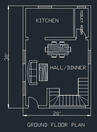
CREATING GROUND FLOOR PLAN
- First open the autocad and set the maximum and minimum limit of the autocad screen using the
- Next draw the plan from the ground floor then draw the plans using the line command and use to put the dimensions using the Dimlinear command
- draw the doors and windows using the standard dimensions used in the construction field
- Next draw the stairs with the riser of 6” and tread of 12",Next need to write the names of the plans at the bottom
- The plot size is given as 20’x30’ Take X line command to draw a horizontal infinite line and also on the Ortho mode for 90 degrees
- Line With x line draw a vertical line too for vertical distances Type o for offset command and draw a line parallel to vertical line at a distance of 9” as we are taking wall thickness of 9” inches
- Type o for offset command and draw a line parallel to 2nd vertical line at a distance of 10’ for the length of stairs
- Again, type o for offset command and draw a vertical line of 6’ parallel to 3rd line.
- Type o for offset command and draw a line parallel to 4th line at a distance of 3’ for 2nd lane of a staircase.
- Now type o for offset command and draw a horizontal line from 1 horizontal line at a distance of 9” for wall thickness.
- Take o for offset command and draw a horizontal line from 2nd horizontal line at a distance of 6’ For the landing of staircase. Type o for offset command and draw a 8 horizontal lines from 3d horizontal line for staircase as we are taking thread distance as 1’for the staircase.
- Type T for trim command and erase the unnecessary lines in the drawing Also erase the outer lines which are outside of the drawing
- We are taking main door (entrance) as just besides the staircase and the dimensions of main door are 3’x6’11”
- Leave the distance of 9” from both the sides of the door and take distance of 6’9” in length for the door.
- Type T for trim command and erase the unnecessary lines of drawing, Type o for offset command and draw a vertical line from door line at a distance of 6100mm for the living area.
- Again, take o command for offset and draw a vertical line for the inner wall thickness of 4” as the wall of living room. Leave a opening for the next rooms.
- Draw some entities of living room like sofa set and TV in the living room as per the adjustable sizes.
- For drawing the curves used in the drawing of the sofa set use curves and command as per required sizes
STEP-2
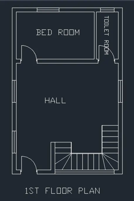
CREATING 1ST FLOOR PLAN
- The plot size is given as 20’x30’ Take X line command to draw a horizontal infinite line and also on the Ortho mode for 90 degrees
- Line With x line draw a vertical line too for vertical distances Type o for offset command and draw a line parallel to vertical line at a distance of 9” as we are taking wall thickness of 9” inches
- Type o for offset command and draw a line parallel to 2nd vertical line at a distance of 10’ for the length of stairs
- Again, type o for offset command and draw a vertical line of 6’ parallel to 3rd line.
- Type o for offset command and draw a line parallel to 4th line at a distance of 3’ for 2nd lane of a staircase.
- Now type o for offset command and draw a horizontal line from 1 horizontal line at a distance of 9” for wall thickness.
- Take o for offset command and draw a horizontal line from 2nd horizontal line at a distance of 6’ For the landing of staircase. Type o for offset command and draw a 8 horizontal lines from 3d horizontal line for staircase as we are taking thread distance as 1’for the staircase.
- Type T for trim command and erase the unnecessary lines in the drawing Also erase the outer lines which are outside of the drawing
- We are taking main door (entrance) as just besides the staircase and the dimensions of main door are 3’x6’11”
- Leave the distance of 9” from both the sides of the door and take distance of 6’9” in length for the door.
- Type T for trim command and erase the unnecessary lines of drawing, Type o for offset command and draw a vertical line from door line at a distance of 6100mm for the living area.
- Again, take o command for offset and draw a vertical line for the inner wall thickness of 4” as the wall of living room. Leave a opening for the next rooms.
- Draw some entities of living room like sofa set and TV in the living room as per the adjustable sizes.
- For drawing the curves used in the drawing of the sofa set use curves and command as per required sizes
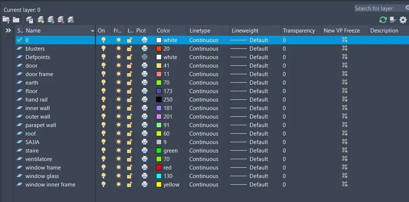
- Using of layer properties for giving the different types of Colours we can use layer properties which is at a home tab
- Click on the layer properties and then click on the new layer and name it as walls and give a colour to the wall
- Again, create a new layer and name it as stairs and select colour for stairs. Again, create a new layer and name it as doors and select colour for doors Again create a new layer and name it as windows and select colour for windows.
STEP-3
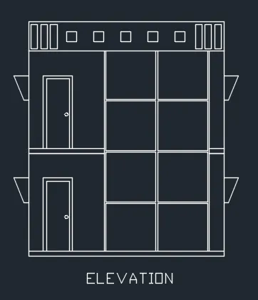
CREATING FRONT ELEVATION
- For the front elevation Type L for the line command and draw a horizontal line of as the length of the plan is 20’ feet
- Type o for offset command and select a horizontal line of 6m and make an offset to the upward side at a distance of 600mm for the sand filling.
- Type o for offset command and make a line at a distance of 5” from the 2’ line to the up direction.
- Type o for offset command and make a offset at a distance of 10’ to the upward side for the ground floor height.
- Type o for offset command and draw a line from the ground floor line at a upward distance of 6” for the slab
- We are taking the slab thickness is 6” Type o for an offset command and draw an offset at a distance of 30 mm from the slab line for the weathering course.
- Type o for offset command and draw a line from the 30mm line at the upward direction at a distance of 10’ for the first-floor height.
- Type o for offset command and draw a line from the first-floor line at a upward distance of 6” for the slab.
- We are taking the slab thickness is 6” Type o for an offset command and draw an offset at a distance of 1” from the slab line for the weathering course.
- Type o for offset command and make an offset of 3’ from the 30mm line at up direction.
- Type L for line command and draw two vertical lines from that 20’line and complete the rectangular structure for front elevation.
- Type TR for trim and erase all unnecessary lines of the drawing
- Type o for offset command and draw an offset from the very first and very last vertical line to the distance of 6” as they are the external walls of the structure.
- Type TR for trim and erase all unnecessary lines of the drawing.
STEP-4
EXTRUDE THE PLAN
- Now take the ground floor plan, Copy the entire plan.
- Erase all the dimensions of the plan and also erase all the text of the plan
- Press on the upper button which is situated just besides the plan direction. Convert the top view of the plan to the 3D view
- Press enters, Now, we want a 3D plan so for that convert the 2D section to the 3D modelling.
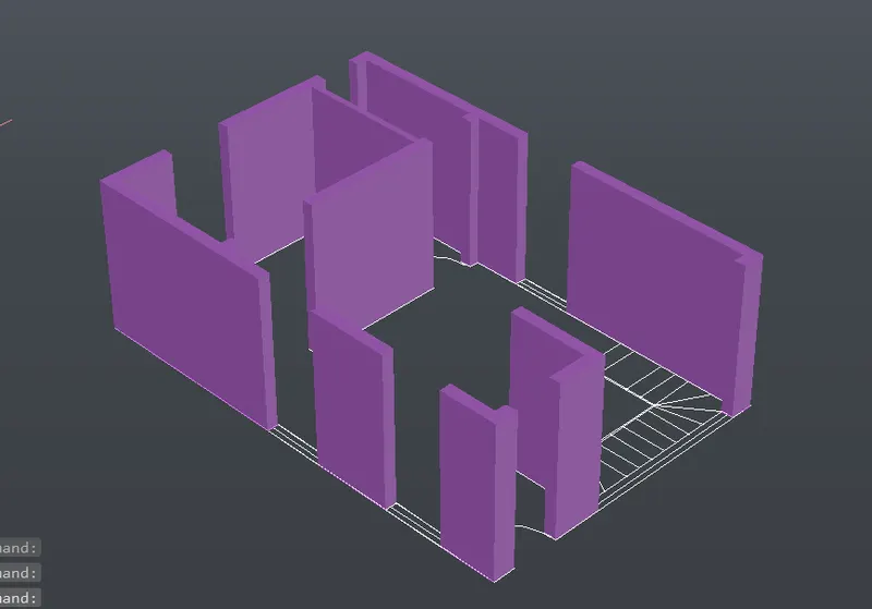
- Now, type BO for boundary command and type on "pick the inner point" Select all the inner points of the lines which represent the walls of the plan.
- Type EXT for extrude command and select all the poly lines in the plan and press enter. We want to create the walls so we will extrude the wall in upper direction at a height of them in layer properties create different types of layers for the doors, windows, stairs etc.
- Press enters, after entering the whole plan will extrude in upper or lower direction 10’ as the height of wall is normally
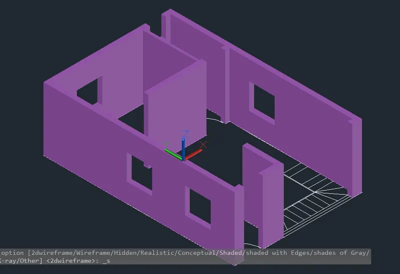
- Only leave the poly lines of the windows and the doors as we need to leave space for Go to the layer properties and choose layer for the walls as per your choice
STEP-5
CREATING OF WINDOWS, DOORS AND STAIRS
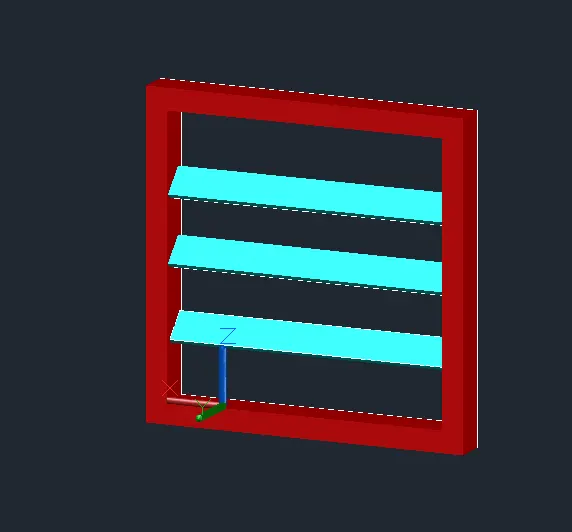
- Now, as we left the section for the windows, we have different types of windows such as 3’X4’ and 2’6”x2’6”
- The height of all the windows is same as 3’ And the height of the wall is 10’ So, type EXT for extrude command
- select all the window poly line and extrude all the windows in upper direction at a height of 4’ We are leaving space of 3’ for the windows Now press on the top view of the plan.
- Type REC for rectangle command and create the rectangles for all the window from the top view.
- Type BO for boundary and select the "pick the inner point and press inside the rectangles and press enter.
- Type EXT for extrude command and select all the rectangles and press enter, extrude all the rectangles in downward direction at a height of 3’ By this all the windows are created.
- Now again go to the layer properties and select the proper suitable colour for the walls.
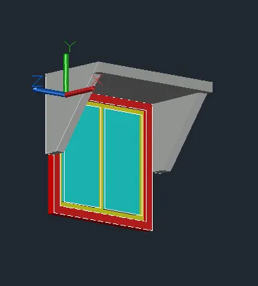
- Create a rectangle of respective windows and create rectangles inside all the rectangles which represents the thickness of the windows.
- Type EXT for extrude command and extrude all the windows in backward direction at a length of 4’ as the representation of the window.
- Choose a sky colour from the layer properties and place this colour to all the windows which represents the glass Select the windows and place all the windows in respective places as required.
- Type UNI for union command select the whole plan and press enter for converting entire plan in single entity.
- By using the layer properties change the carpet colour of the inside plan.
- Now, for the doors we need to extrude the given door and place it in the required position.
- The main door size is 3’x6’11”, Type BO for boundary command and select the lines of the inner portion of the door.
- Press enters, By layer properties choose a colour for the door. Type 3DF for 3DF command and select all 4 corner points of the door for placing the colour inside the door.
- Now type EXT for extrude command and extrude the door inside the direction at a distance of 6” as the width of the door.
- Select the door and press on move command. And move the door at respected position by the corner point of the door.
- Create the bedroom as well as the bathroom and toilet doors by the same procedure. And place all the doors as required position.
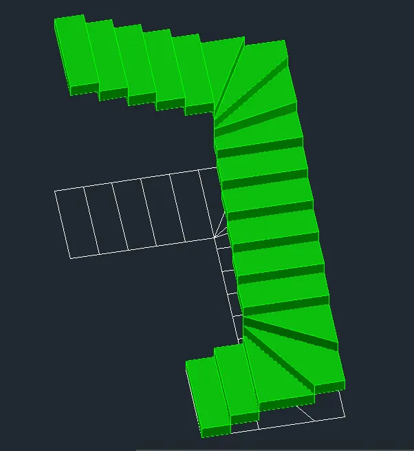
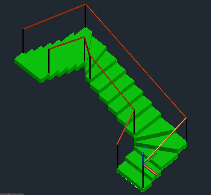
- Now type BO for the boundary command and select the inner point of all the stairs and also select the landing part of the staircase
- Type UNI for union command and select entire staircase for the union and press enter.
- By this the staircase will become the single entity. Copy the entire staircase and paste it in side of plan for the first-floor plan. Because the dimensions of staircase in first floor plan is same.
STEP-6
CREATING 3D VIEW OF PLAN
- Type REC for rectangle and create a rectangle of 20’X30’
- Type on layer properties and select the colour for the slab Type on 3DF in command box and select all the corner points of the rectangle and press enter.
- The layer will be created, Now type EXT for extrude command and select the rectangle and extrude the rectangle at a downward direction at a distance of 14.5” and press enter
- As this is the general size of the slab Type CO in command box and copy the slab rectangle and place it in the upper side of the plan as this represents the slab of the first floor.
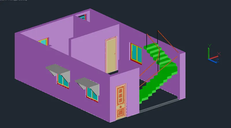
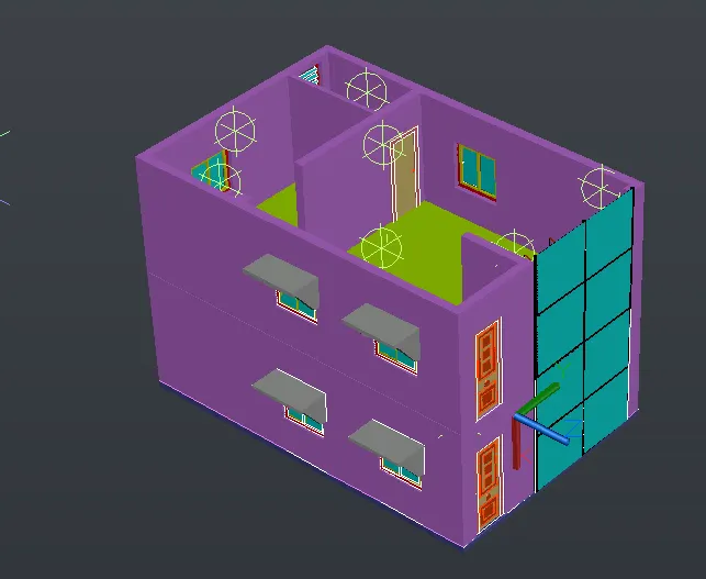
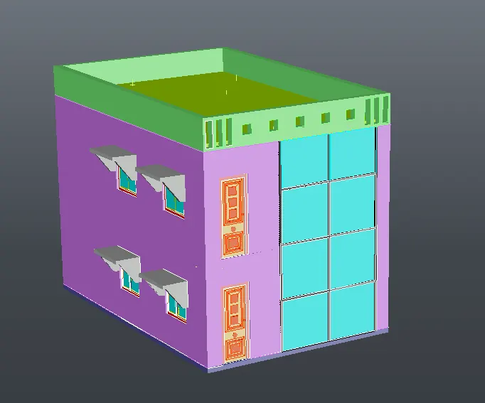
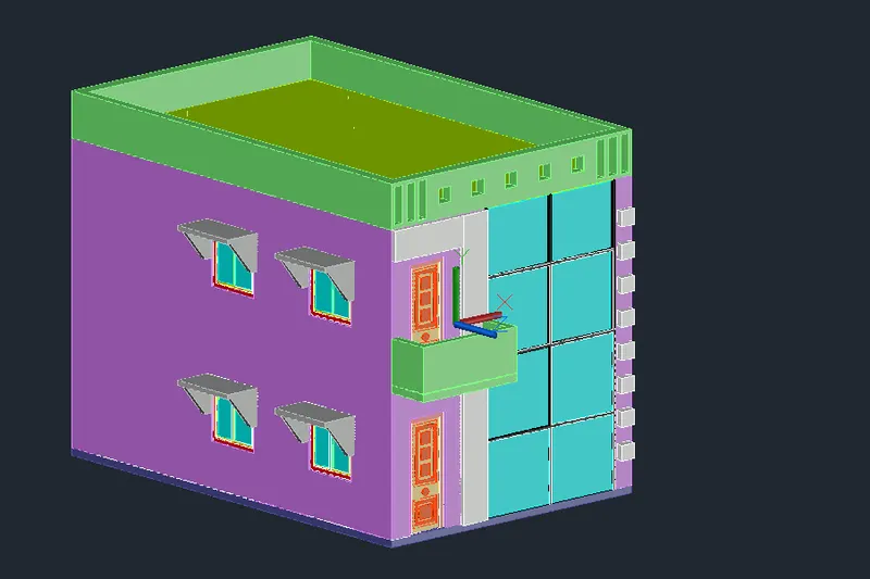
- Now, we have already copied the ground floor extruded plan in the design,
- Copy that plan and place that entire plan in the upper side of the first-floor plan as this represents the first floor of our design.
- Because the dimensions of first floor and ground floor are same.
- After copying the plan, also move the staircase and all the doors, windows to the first-floor plan and all the sizes of the doors, windows and staircase is same in the first floor plan.
- Also move the copied slab in the upper side of the first floor as the representation of the slab of terrace section
- Type REC for rectangle and create a rectangle of 20’X30’ of dimensions.
- Create another rectangle inside of this rectangle by leaving the space of 9” which represents the wall of the terrace.
- Type BO for boundary command and select the "pick Inner point" After this, select the inner point of both the rectangles
- Select the point which is between the two lines of the rectangle and press enter Type EXT for extrude command and select the boundary line.
- Now, extrude this wall of the terrace at upper side at a distance
- By clicking on layer properties select the proper colour for the wall of the terrace and place it.
- Type H for hatch command and select the hatch pattern for the floor of the terrace and press enter.
- Now, type MO for move command and move this entire terrace to the upper side of the second floor.
- Create a bigger size rectangle and move this whole structure above that rectangle.
STEP-7
CREATING CAMERA VIEW AND RENDERING
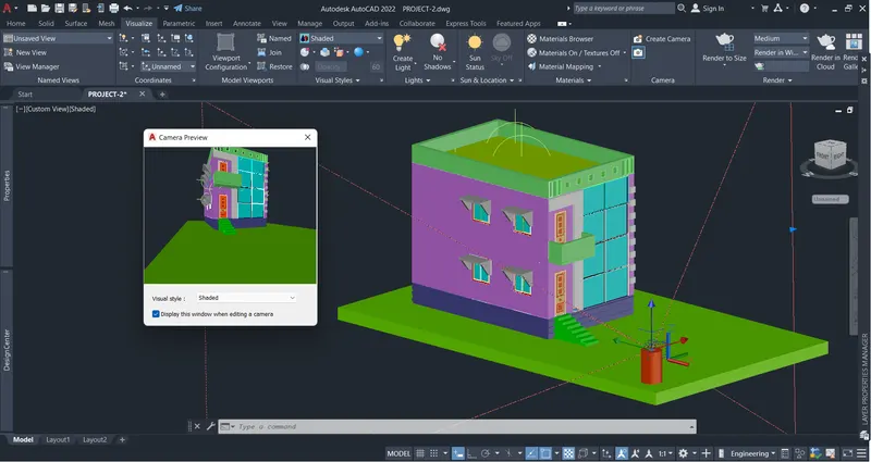
- Now, type CAM in command box for camera and enter
- After entering, camera will appear and place that camera in a respective site Click on the camera and move cursor to the drawing and take a proper size for the photo.
- Take a perfect photo of the entire drawing. Name the photo as cam-l. Now, go to the custom view which is in left side of the screen.
- Also click on the custom model view and click on the com 1. The photo will appear
- Take a perfect photo of the entire drawing. Name the photo as cam-l
- Now, go to the custom view which is in left side of the screen Also click on the custom model view and click on the cam-1
- The photo will appear. Go to visualize and click on no shadows and select the full shadows, click on sun status and click ok keep the default line turned on.
- Click on sky off and click on sky on. Click on the render and select the render size as full HDTV
- Click on the corner arrow and on the environmental exposure. Click on the rendering tab and the rendering will start.
- After rendering done, save the picture of rendering
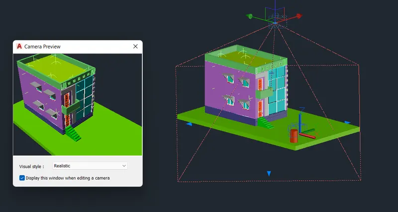
RESULTS
The three dimensional model of the residential building with a renderd view is created successfully in the Autocad 2022 in detailed manner.