Project 2_Analyze and Design the RC office building as per IS standard code in TEKLA STRUCTURAL DESIGNER
After opening the software,we open a new file.
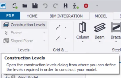
Where then we create the different levels.To do that,we go to MODEL Tab>Construction Levels.
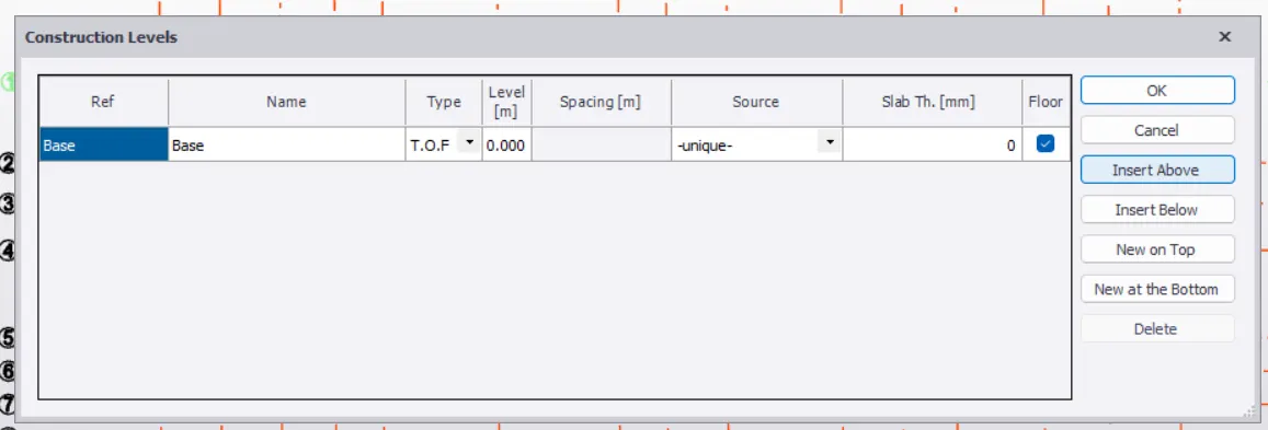
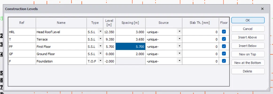
Where then using the available options we do create the required levels.
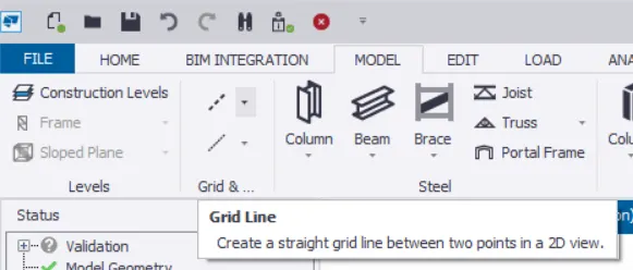
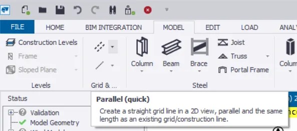
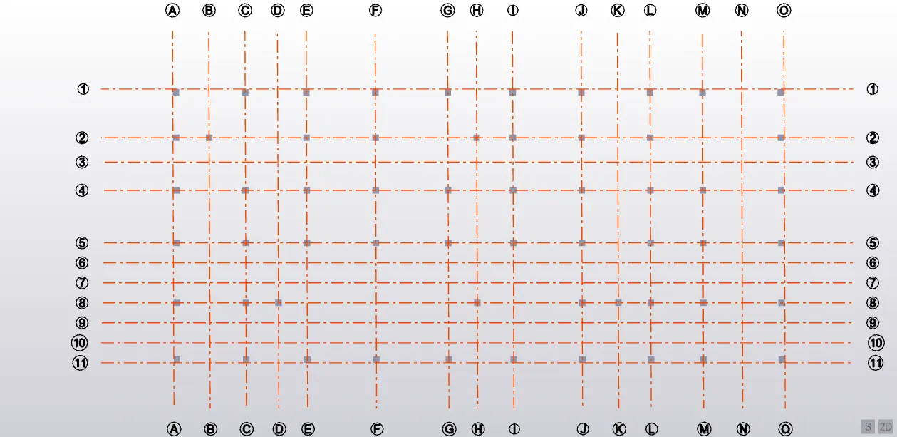
Then we form the grid lines using the options of Grid Line and Parallel(quick) present in the MODEL Tab.
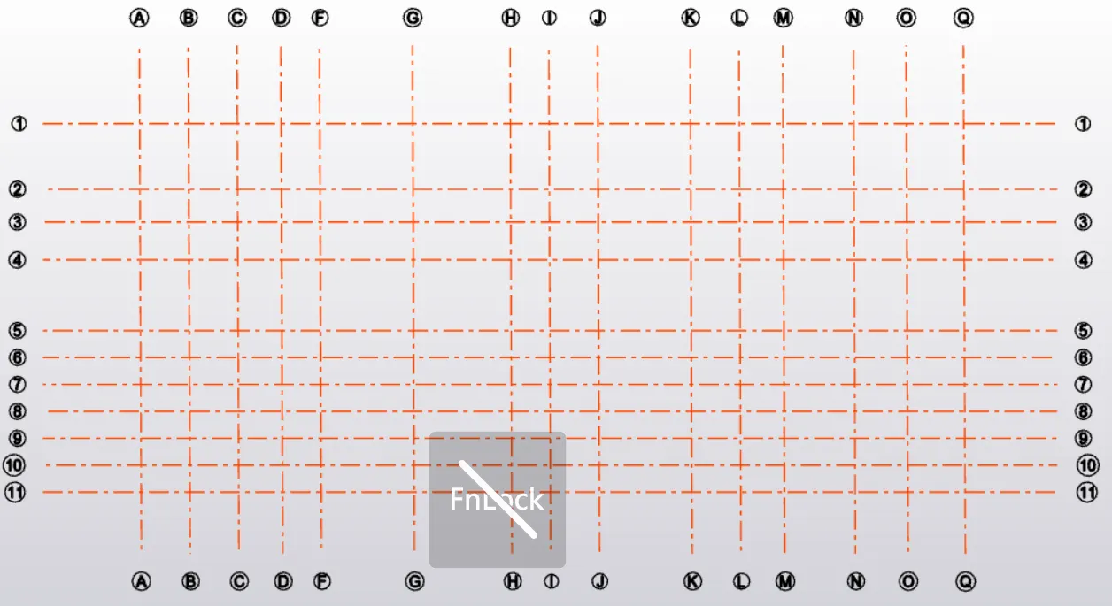
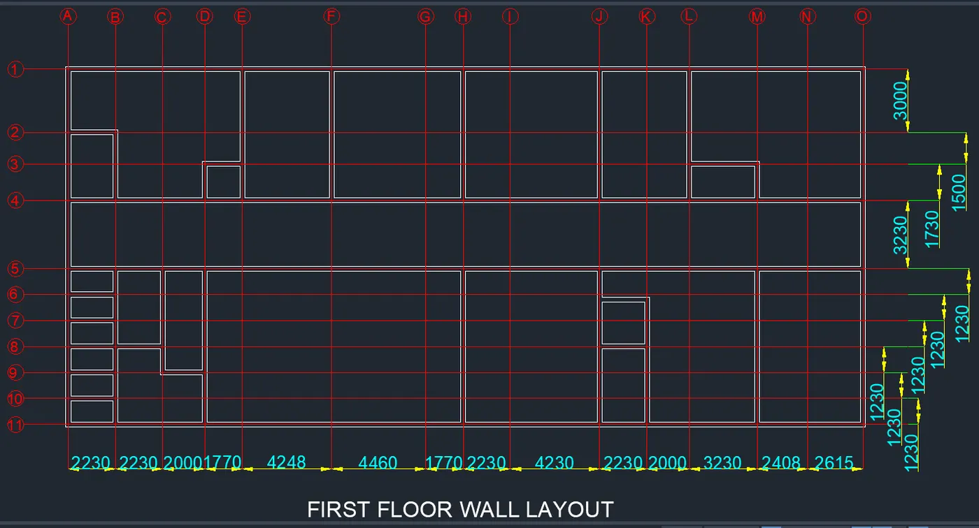
We form the above grid lines and the levels based upon the provided data.
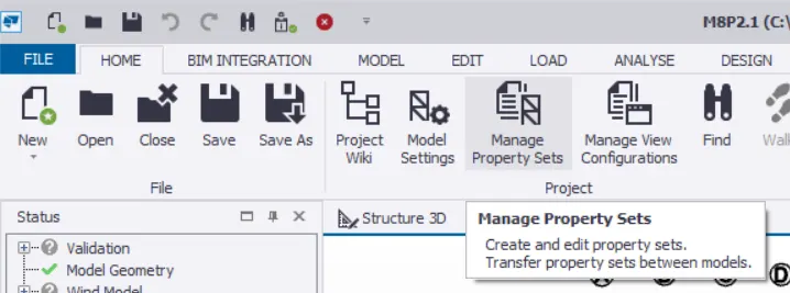
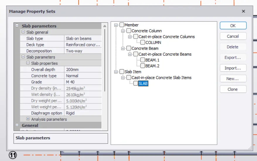
We then go to HOME Tab>Manage Property Sets and create the required members.
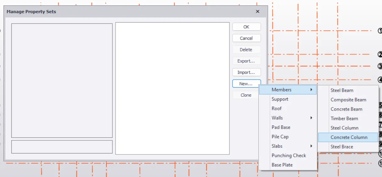
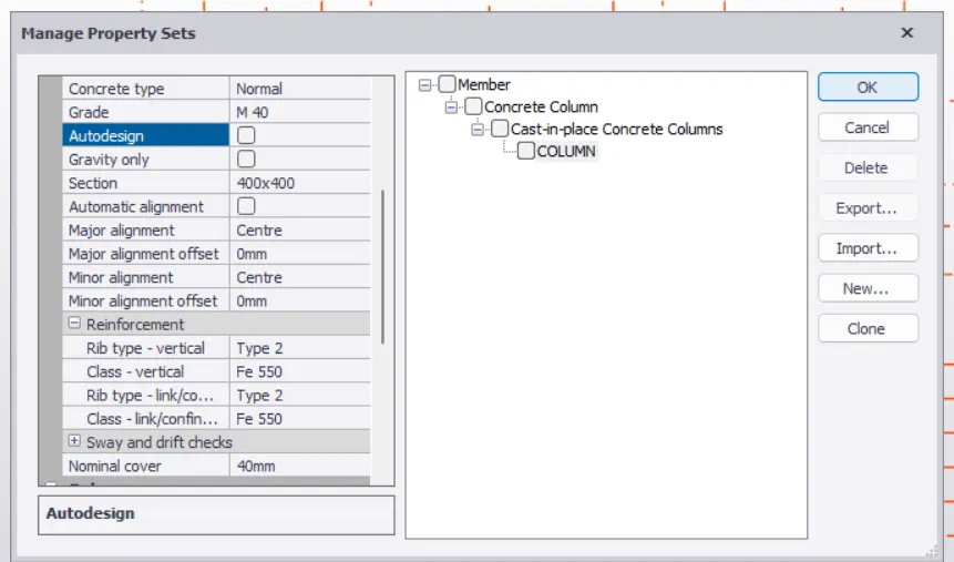
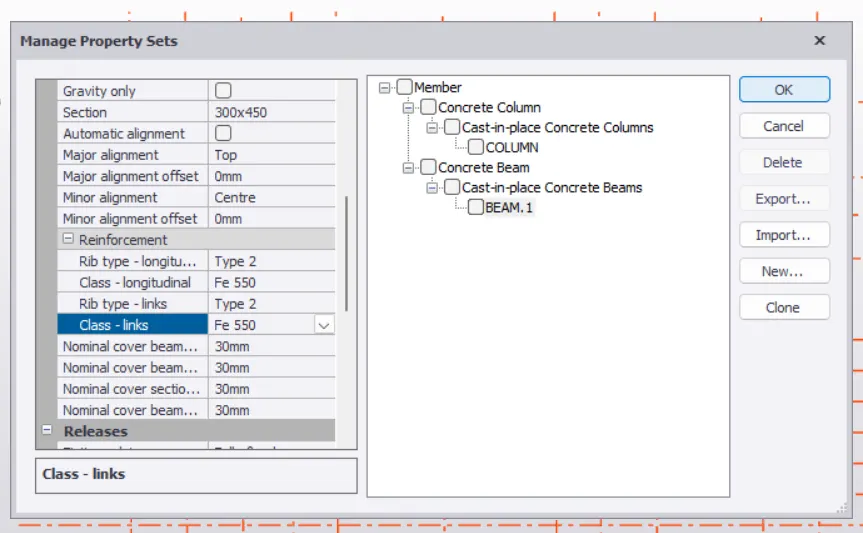
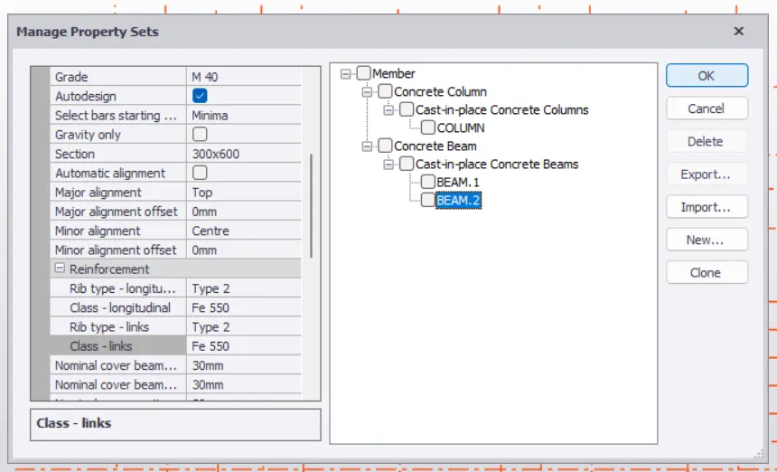
In this manner,we create the beams and columns for a while and we do create the other basing upon the require after.
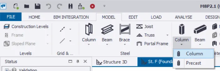
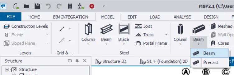
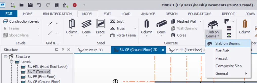
Then we select the required element in the MODEL Tab and then place it on the grid lines as per the layout defined.
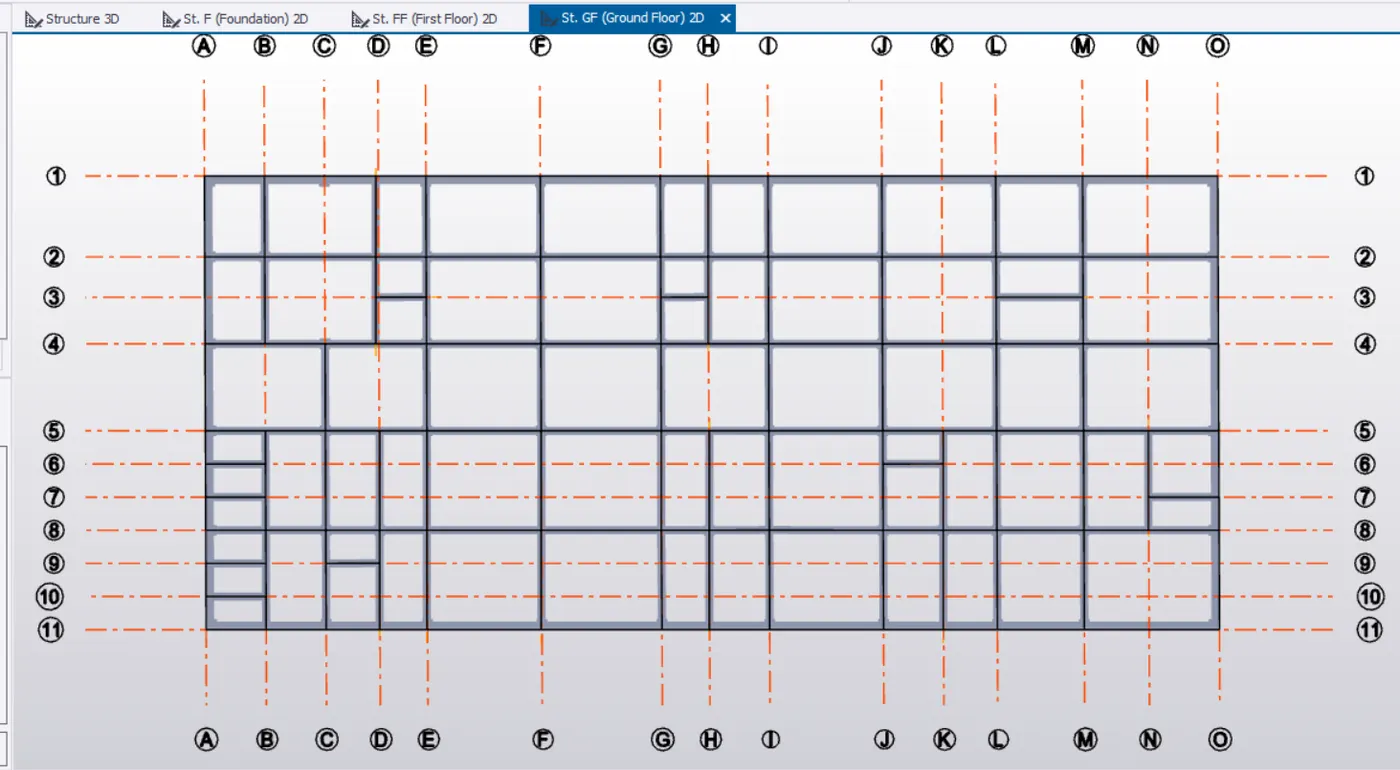
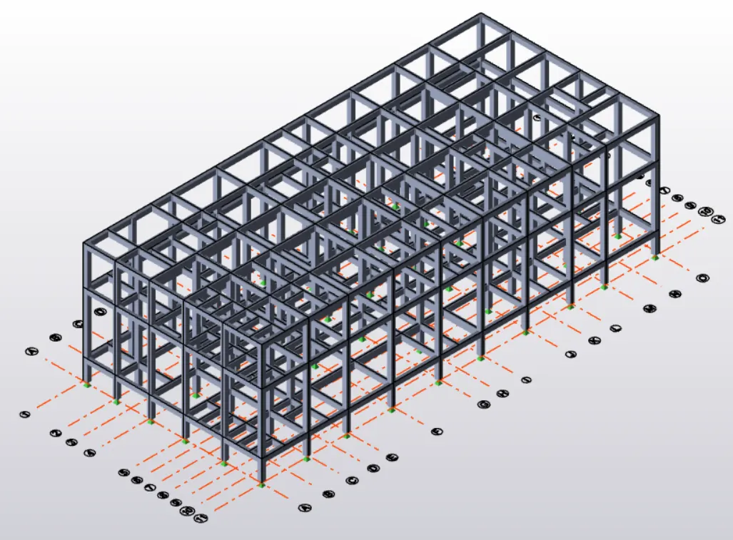
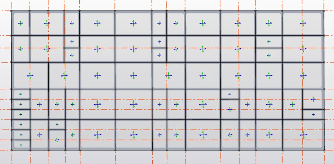
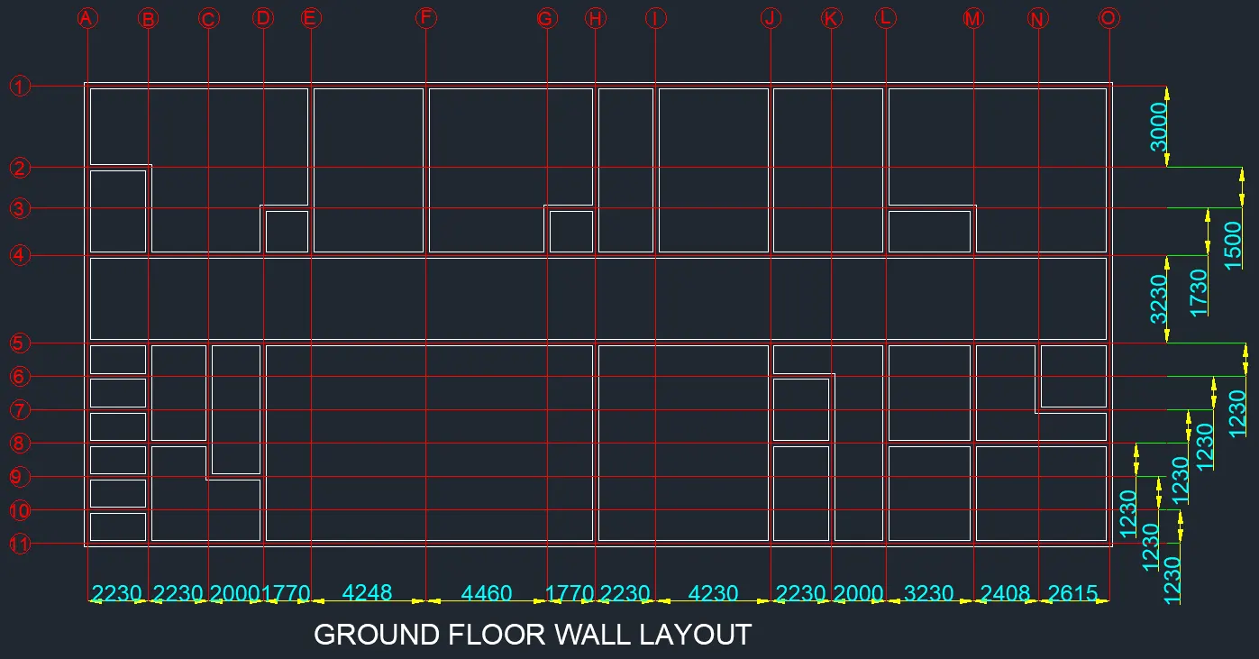
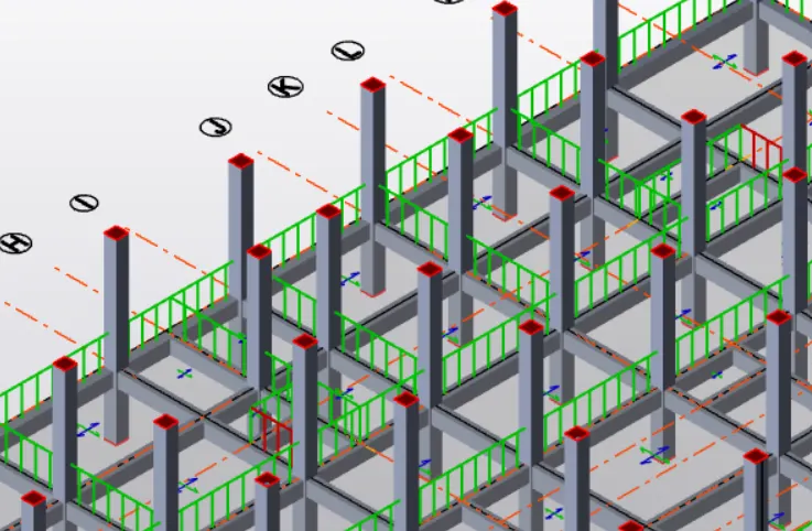
Where we do create beams as per the wall layouts and then apply the wall loads basing upon these wall layouts only.
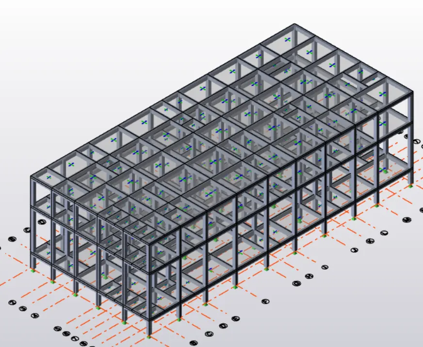
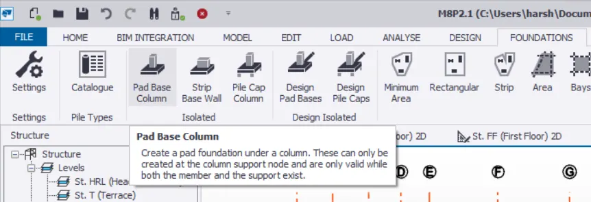
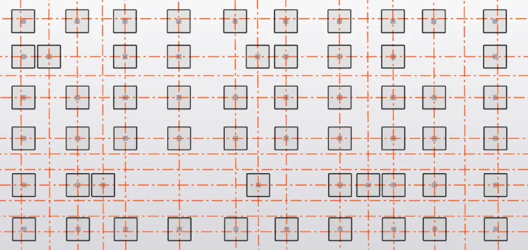
After placing the slabs,we place the footings.Where we go to FOUNDATIONS Tab>Pad Base Column and we place the element without any provision of the further details as we have a option of self design of the footing in this software.
Where as for the beams and columns as well as for the slabs we do give certain parameters such the concrete grade,reinforcement grade,size,cover,etc.
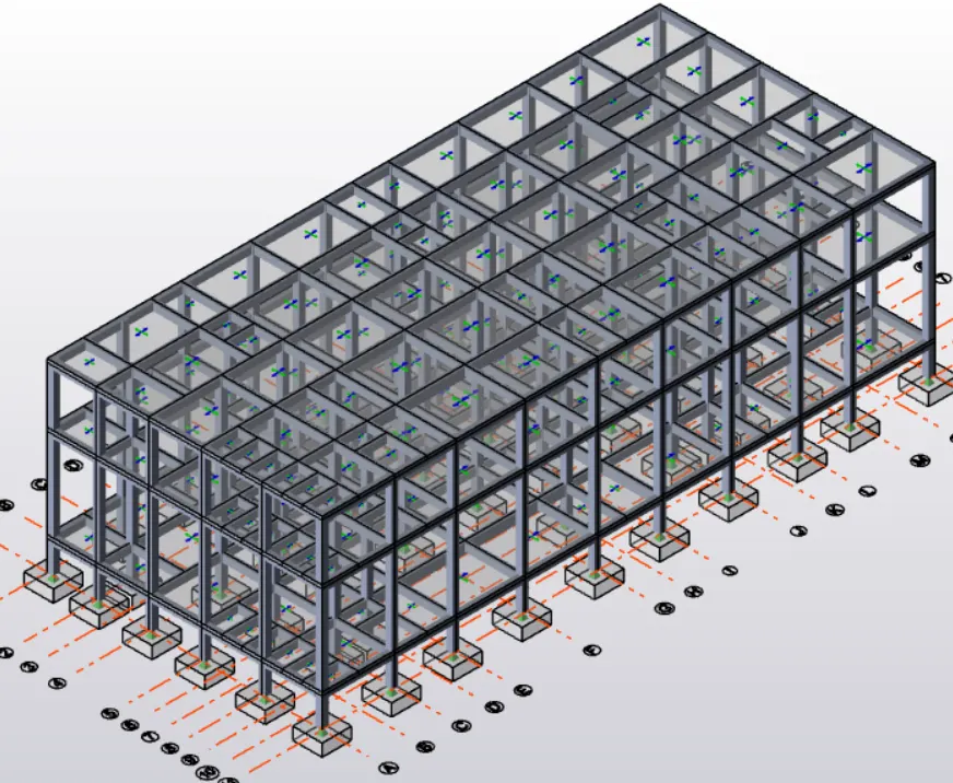
After the modelling of the structure,we apply the loads on to the structure.So,we have to create the different cases for the easy application of the loads.
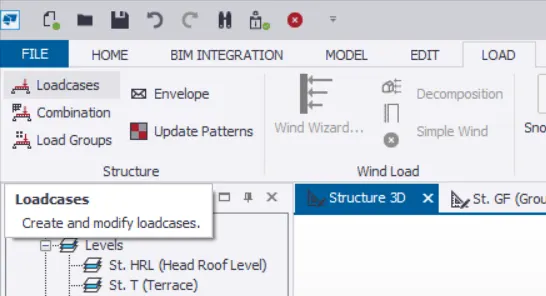
We go to LOAD Tab>Loadcases and then create the required basing on the options available and then requirement.
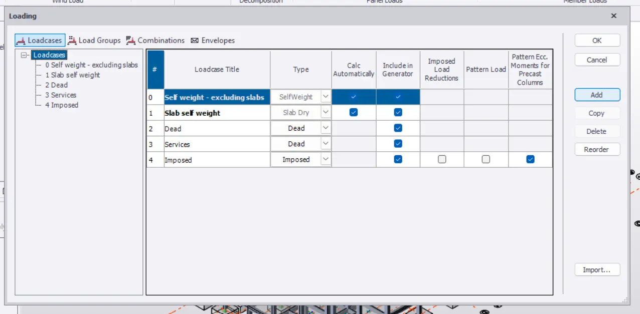
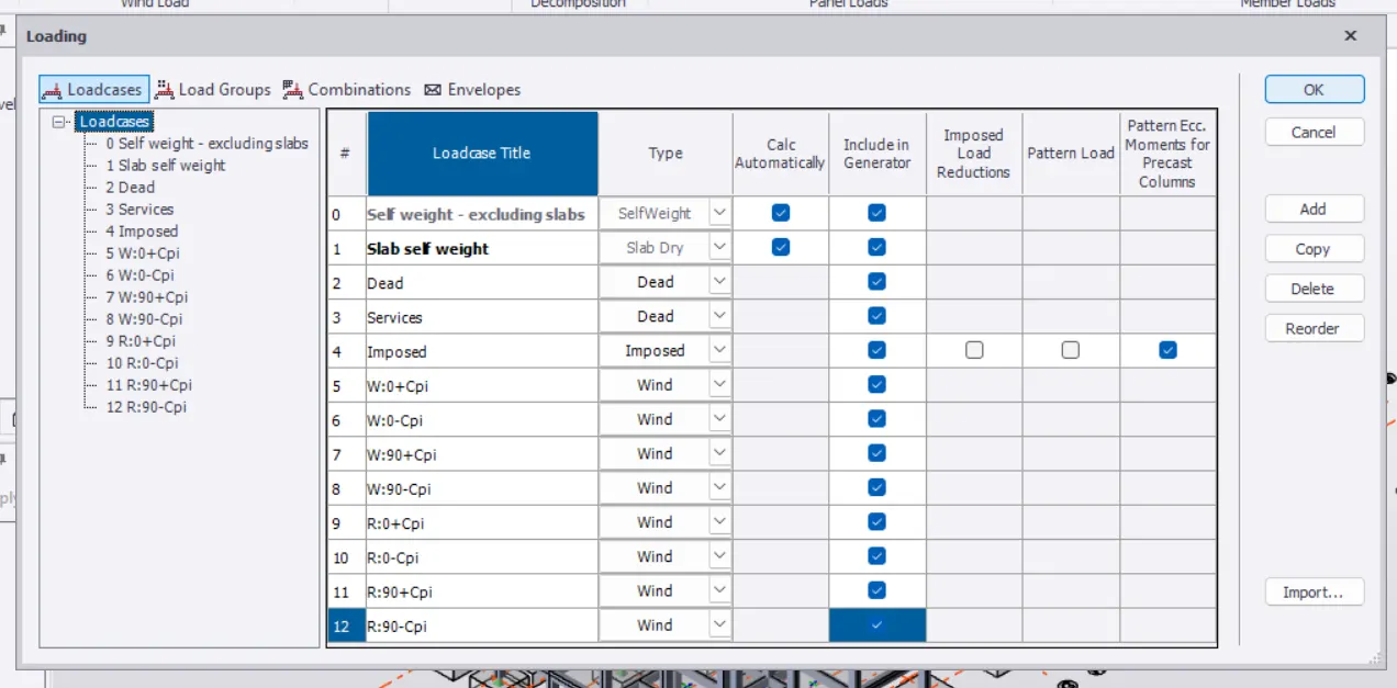
After the successfull creation of the load cases,we do select the specific load case from the bottom left part and then apply the loads on to the model using the options available in the LOAD Tab.
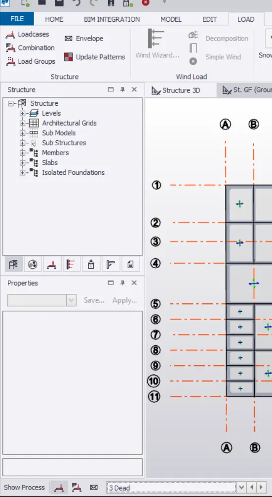
And then we apply the different loads as per the requirement.
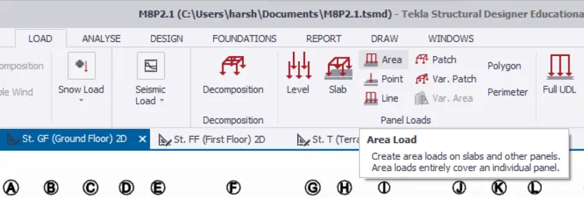
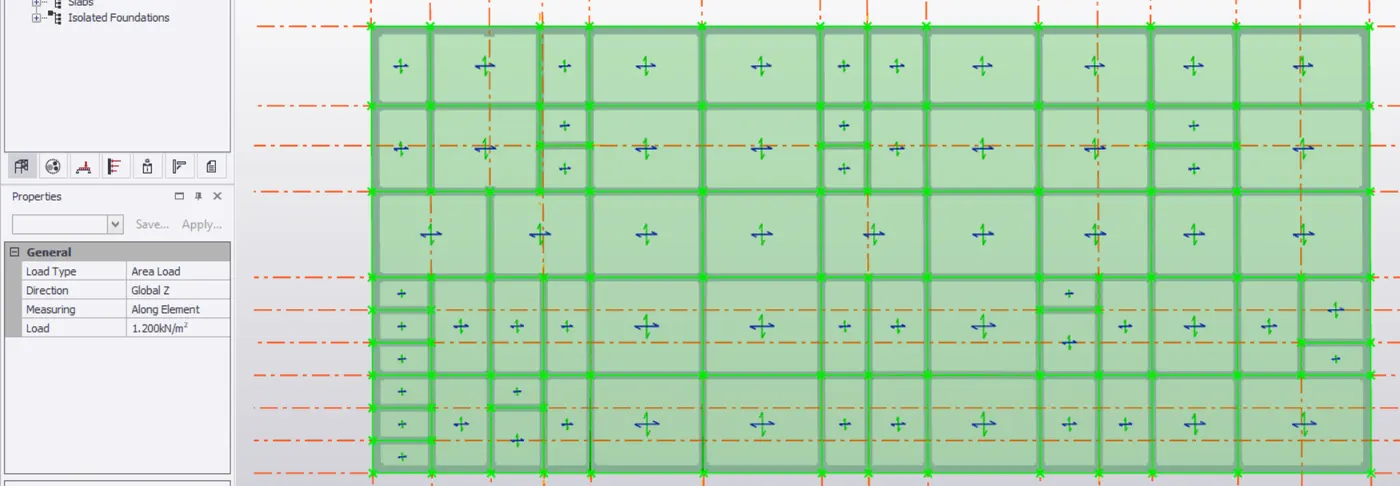
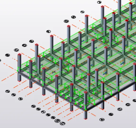
We use the Full UDL option to apply the brick wall load when the wall runs throughout the beam and we use the option of Line when the wall runs only for a certain part of the beam.
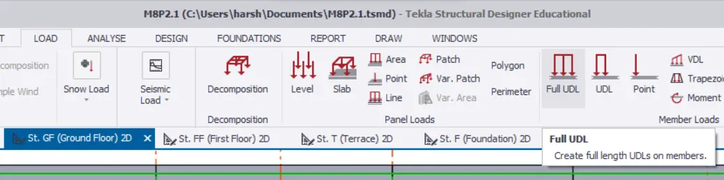
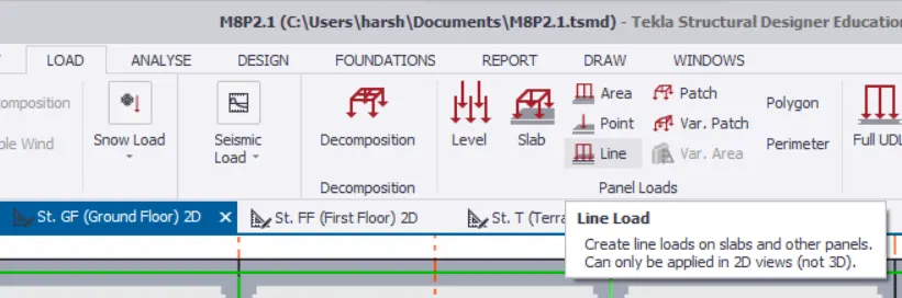
Using the above 2 options,we apply the wall load basing upon the wall layout.
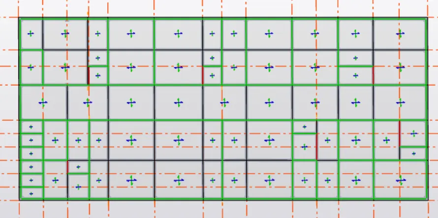
And then we apply the live load.
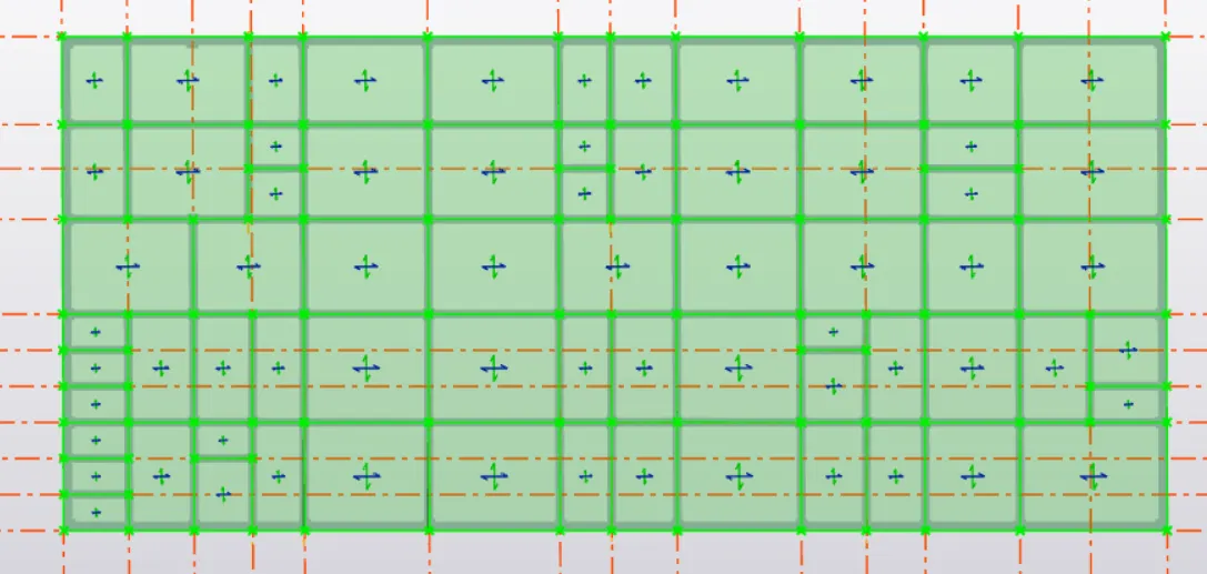
And then we add wall panels to the model.
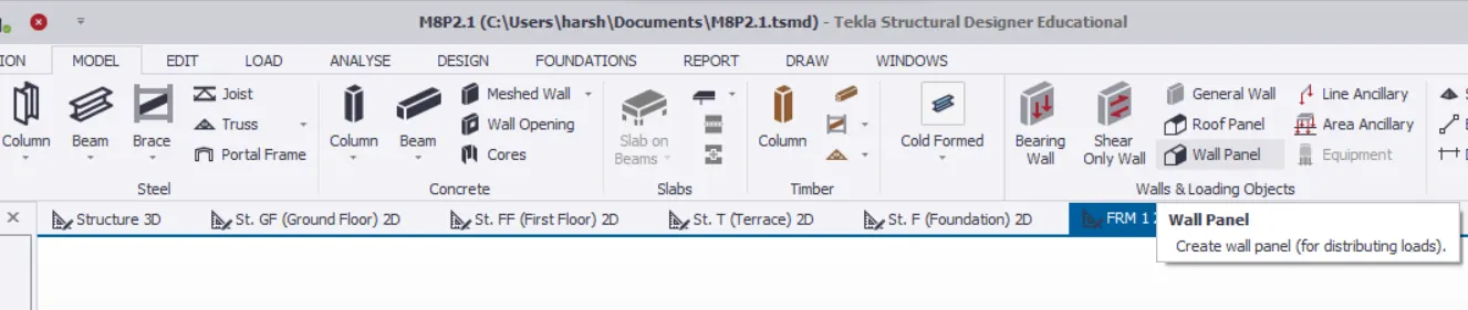
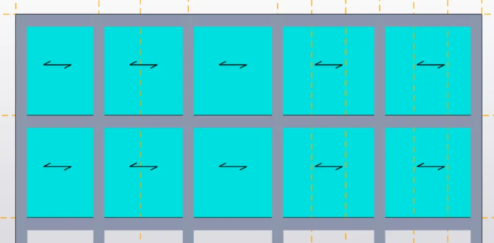
And then we apply the wind load on to these wall claddings.This Wall Panel is just an option to redistribute the wind load on to the columns and to the beams.
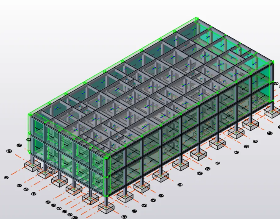
In the similar manner,we apply the roof loadings on to the roof.
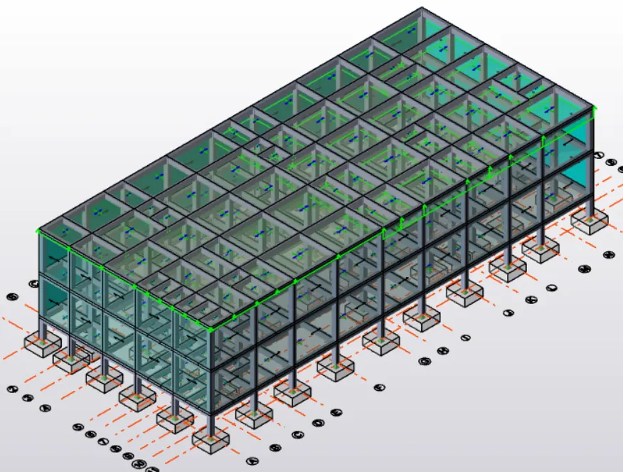
The above wind loading intensities are calculated.
And then we go to LOAD Tab>Seismic Load>Seimic Wizard...
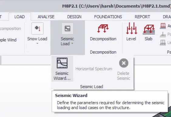
Where then we select the required parameters in the next few resultant tabs.And then we analyze the model.
To do that we go to ANALYSE Tab>1st Order Linear.
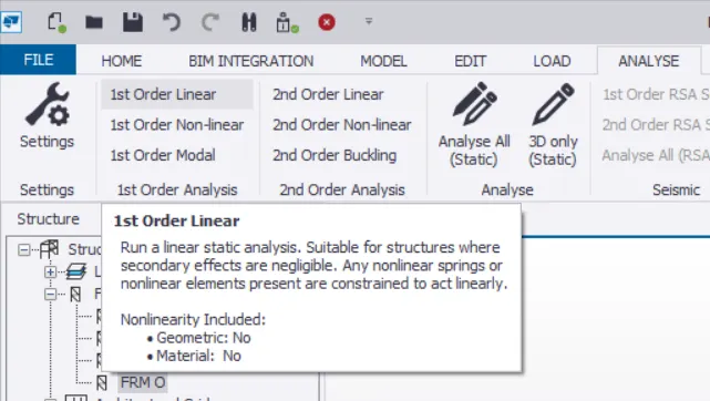
Then we select an individual member for designing.
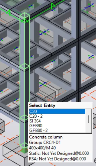
Where then we go to Check Member>Static.
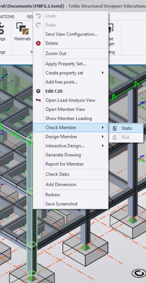
Then we can find the required results of that specific member.
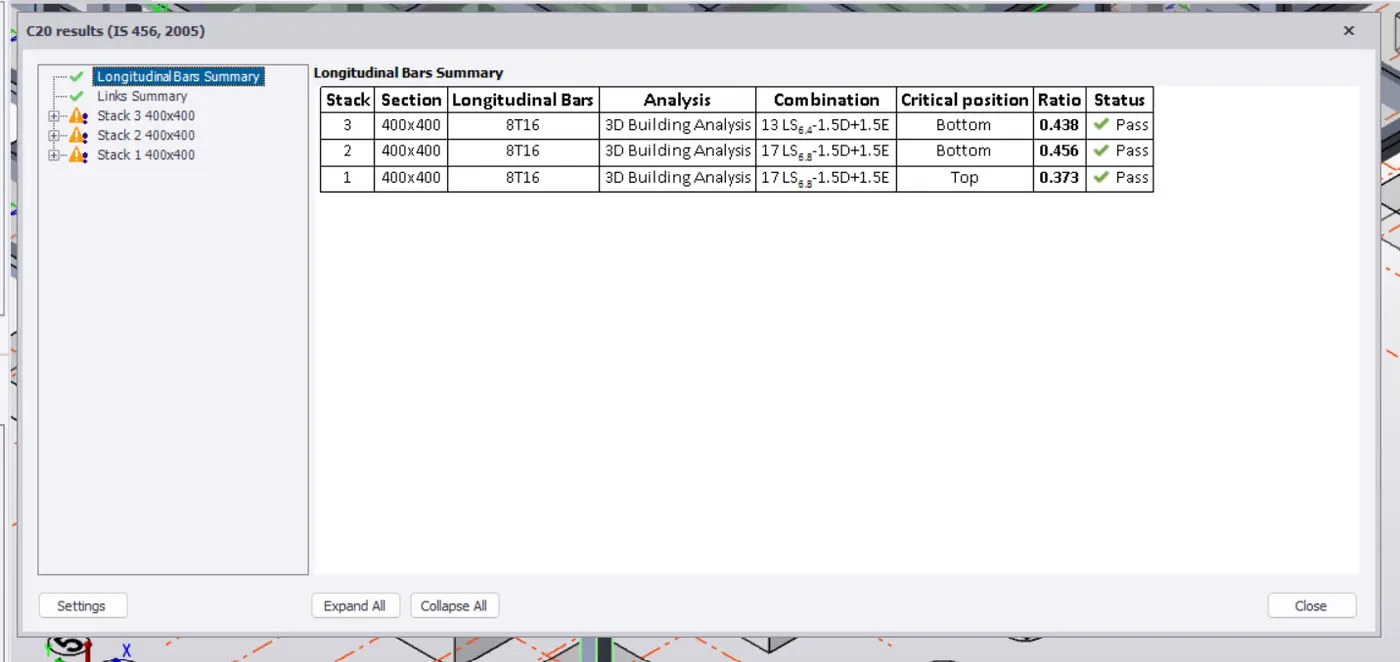
In this manner we can check the results of all the beams and columns.
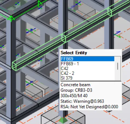
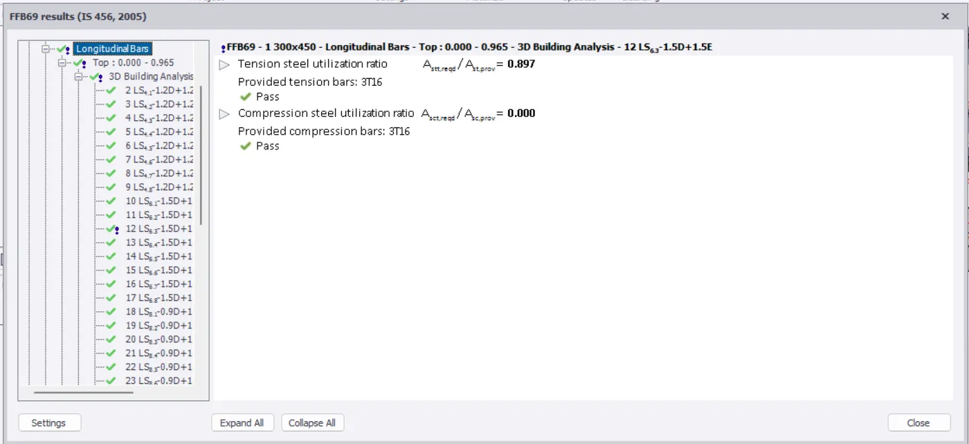
Where we can find the reinforcement data.Then we use the option of Design Member to design the footing after the selection.
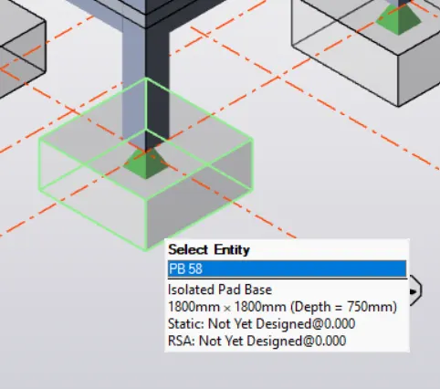
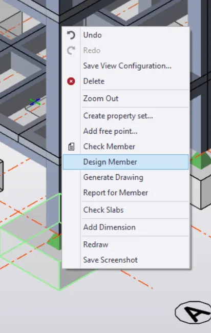
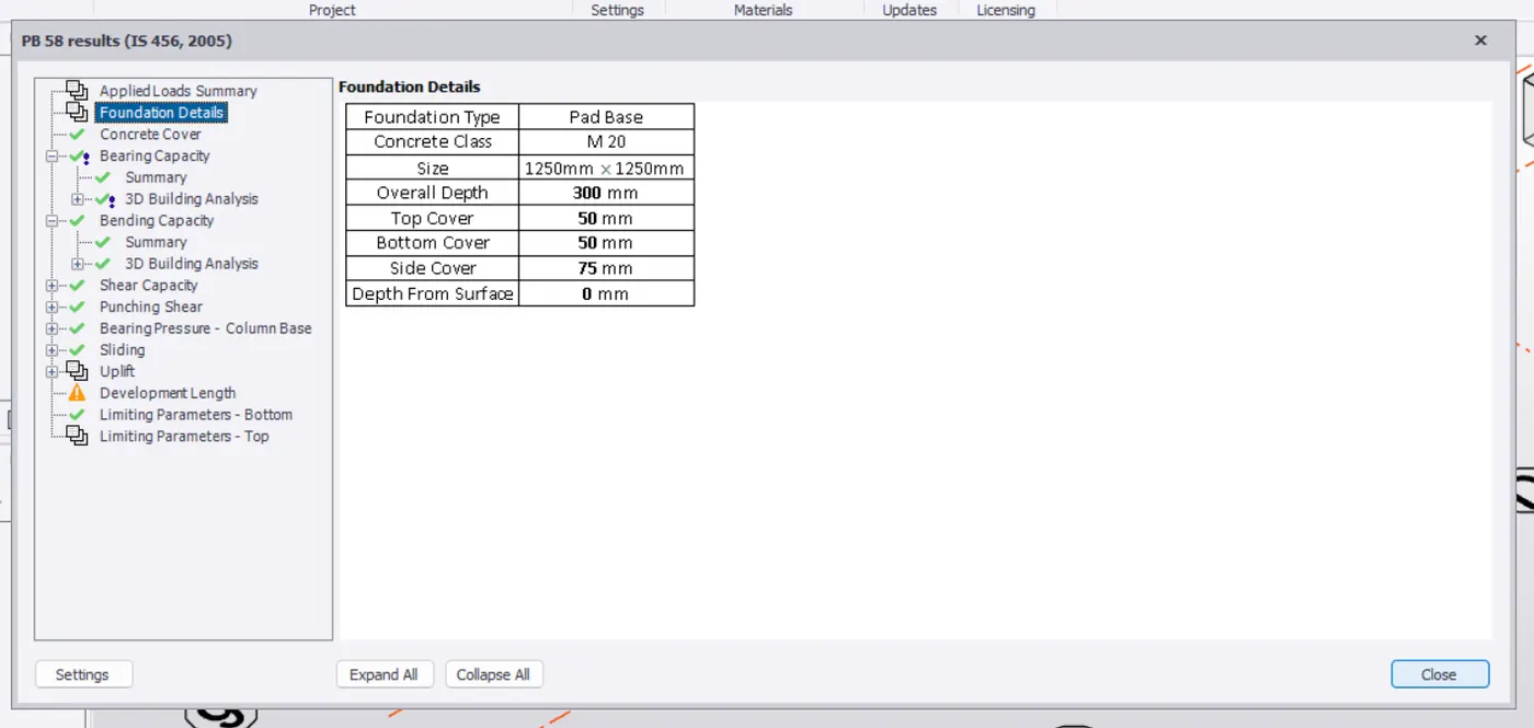
And we can find the further results in the resultant tabs and even in the Properties Tab at the left bottom.
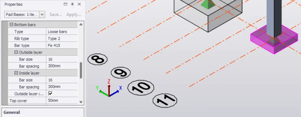
Then,we can even form the reports to all the members using the option of Report for Member.
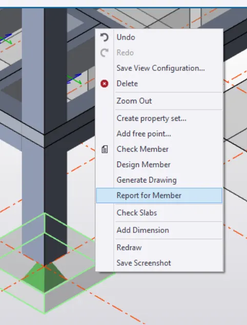
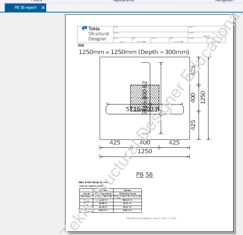
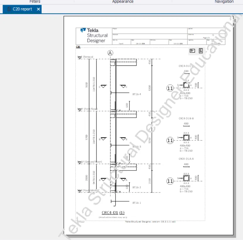
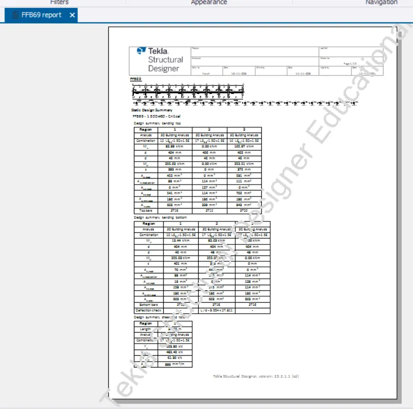
In this manner,we can create the individual report for all the members.
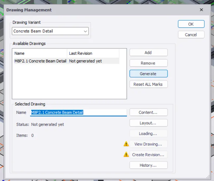
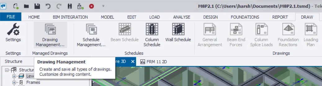
To generate the drawings,we go to DRAW Tab>Drawing Management...
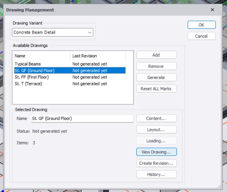
Where then we select the required Drawing Variant and then add it use the option of Add and name it required.
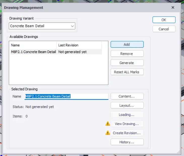
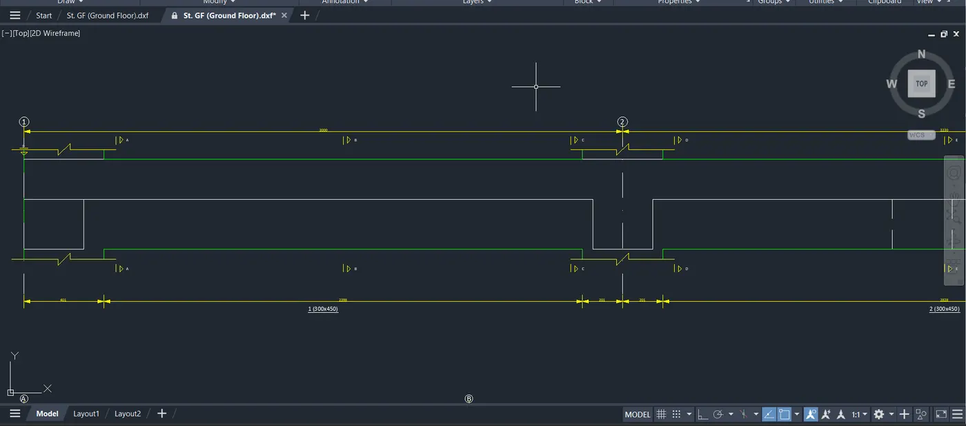
We then click on the Generate and then to view it we use the option of View Drawing... after the selection of the suitable one.