Project 2 Adaptive Cruise Control
1. AIM:
- To develop Adaptive Cruise Control feature as per the Requirement Document using MATLAB Simulink.
- Following all the MBD related processes: Requirement Tagging & Traceability, SLDD creation, Configuration Parameter changes, Model Advisor check & Code Generation.
- Setting Configuration Parameters: enable “Support Floating Numbers” under Code Generation settings.
- with the use of Embedded Coder to generate the code.
- Storage class for Input signals: ImportedExtern; Storage class for Output signal: Export to File; Storage class for local signals: localizable; Storage class for calibration signals: Const.
- And choose sample time for all signals as 0.01s
2.DESCRIPTION:
I. Developing model:
- Open a blank model.
- Add subsystem block into model canvas.
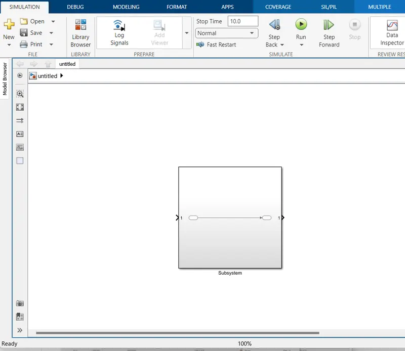
Making some setting changes like off the Content Preview , On Show Block Names . For all this set-up just double click on subsystem block and Goto Format a drop down will appear click on Content Preview.
To On Show Block Names go inside subsystem select blocks and right click ,again do the similar drill as we just did.
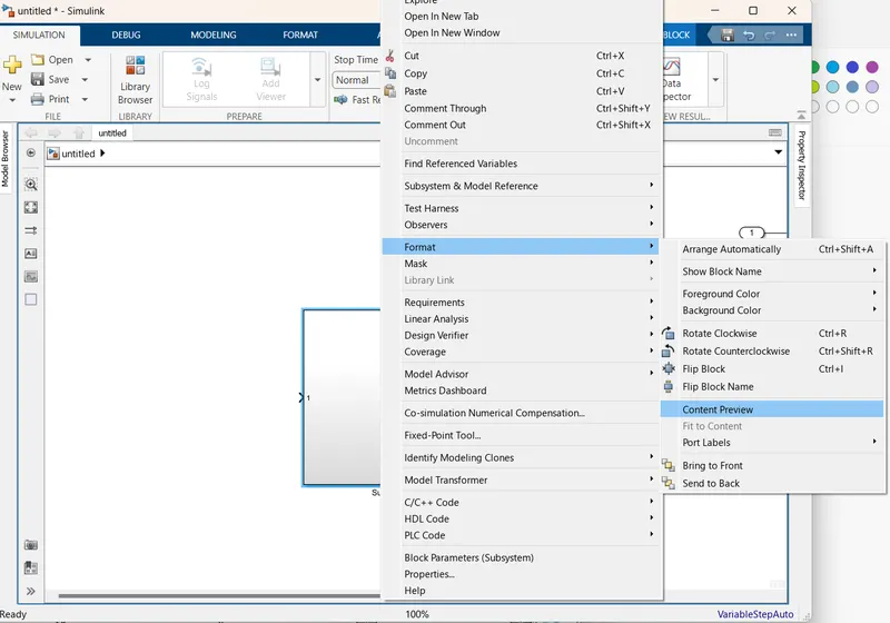
Now replace by default appeared blocks and add a subsystem.
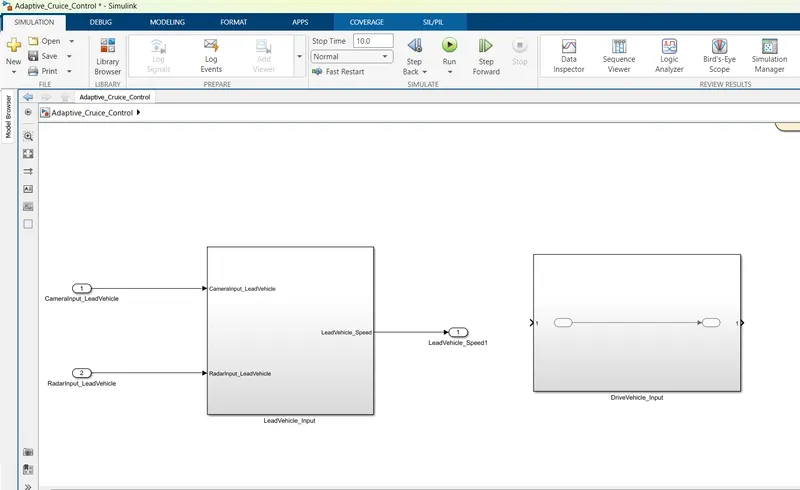
Name that subsystem as LeadVehicle_Input
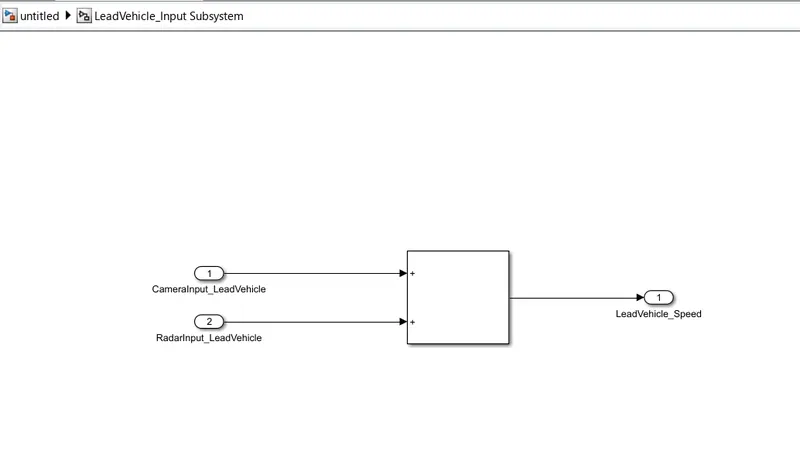
Double tap onto subsystem LeadVehicle_Input , go inside and add all the required blocks.
Make all connections and provide names to two inputs and an output block as CameraInput_LeadVehicle RadarInput_LeadVehicle and LeadVehicle_Speed.
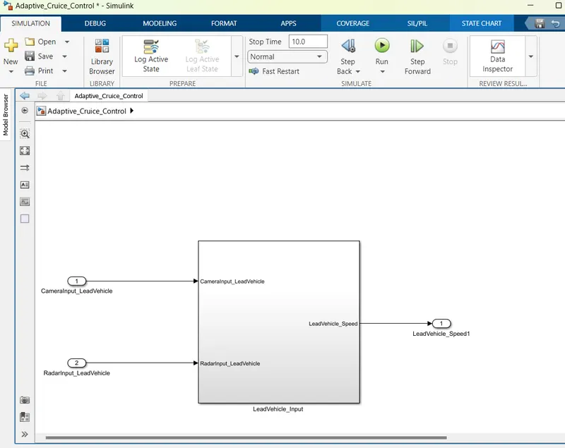
Get out of LeadVehicle_Input subsystem and add same inputs ,output to the ports appearing on this subsystem.
CameraInput_LeadVehicle and RadarInput_LeadVehicle and output is LeadVehicle_Speed.
Create a new subsystem DriveVehicle_Input on the same canvas where LeadVehicle_Input exists.
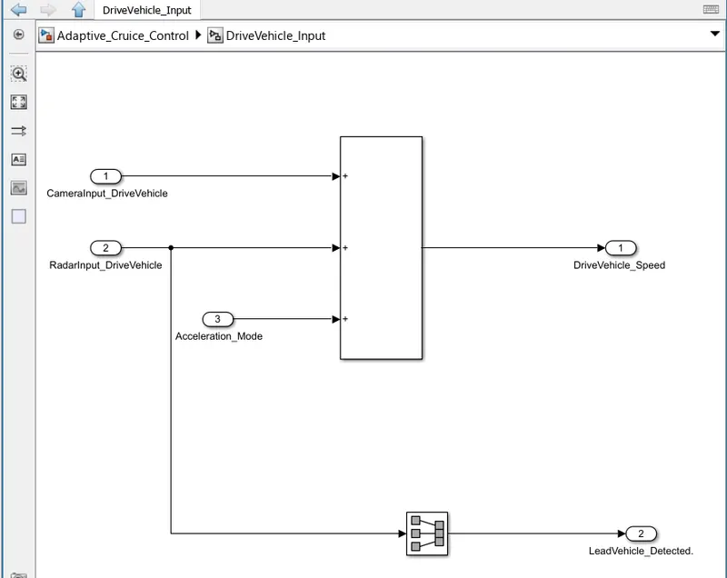
Add all Required blocks inside subsystem DriveVehicle_Input.
There are three inputs to this subsystem CameraInput_DriveVehicle, RadarInput_DriveVehicle and Acceleration_Mode and two outputs are DriveVehicle_Speed and LeadVehicle_Detected.
Acceleration_Mode is actually an output which is fedback as input to this subsystem.
The 2nd output LeadVehicle_Detected is renamed from Input Signal RadarInput_DriveVehicle by use of Signal Conversion block.
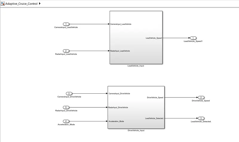
Get out of this Subsystem, add three inputs and two outputs to all the available ports as shown in image below.
Connect them with their corresponding ports.
Now apply third requirement by using State machine flowcharts.
Load a Chart on the same canvas where two subsystems exist.
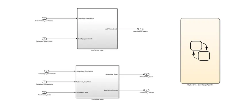
This Chart is consists Adaptive Cruise Control Logic Algorithm.
There are Three Main Modes of ACC : ACC OFF MODE(default) , ACC STANDBY MODE, ACC ON MODE.
There are eight inputs and one output for control logic.
The input signals to this state machine system are (Signal Name: Time_Gap, Set_Speed, Set_Gap, CruiseSwitch, SetSwitch).
Also, the output signals (Signal Name: DriveVehicle_Speed & LeadVehicle_Detected) from requirement-2 is fed back as an input signal into this state machine block.
Additionally, output signal (Signal Name: LeadVehicle_Speed) from requirement-1 is given as an input signal to this state machine block as well.
Output from this subsystem is a signal (Signal Name: Acceleration_Mode) which governs the vehicular speed of the drive vehicle which automatically adjusts its speed & velocity to match the lead vehicle.
To make connections we need to get input and output ports on Chart.
Goto Model Explorer, on the left side of window we can see some listed items.
Find Chart and as we click on it, a blank stateflow canvas open.
Go to top left of window find Add Data in icon tray, click nine times on Add Data as we have nine values combining inputs and output.
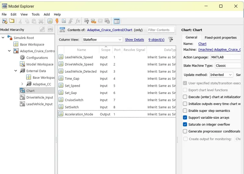
As we add data to Chart we can see all input and output ports are available on the chart.
Make connection of three signals( LeadVehicle_Speed, DriveVehicle_Speed & LeadVehicle_Detected) to their corresponding ports which are the outputs coming out from subsystems LeadVehicle_Input and DriveVehicle_Input.
Also connect output block to the output port Acceleration_Mode.
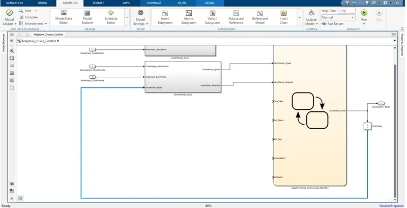
Five more Input blocks need to add for Input ports of Chart.
Go inside the Chart and write control llogic using states and flowcharts.
First of all load a default state which is for ACC OFF MODE, entry is Acceleration Mode=0 in this state.
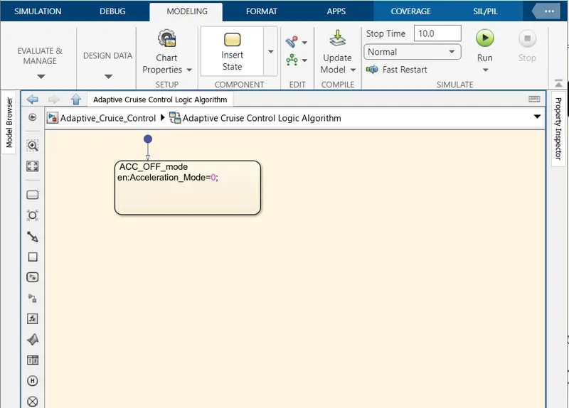
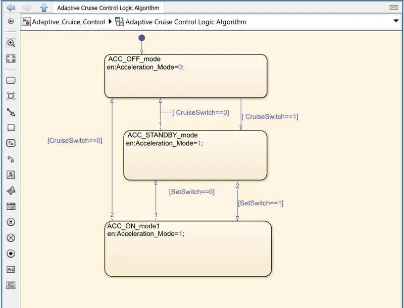
Add a state for ACC STANDBY MODE.
This is the second activated state inside state machine logic. Output signal Acceleration_Mode is at value 1 in this state.
This state is governed by both input signals CruiseSwitch & SetSwitch.
If CruiseSwitch is equal to 1, state ACC STANDBY mode will get activated. If CruiseSwitch is equal to 0, state ACC OFF mode will get activated, from either ACC ON mode or ACC STANDBY mode
If SetSwitch is equal to 1, state ACC ON mode will get activated. If SetSwitch is equal to 0, state ACC STANDBY mode will get activated.
-
ACC ON MODE will be activated when input signal SetSwitch is equal to 1. There are 6 sub states to this state logic: They are:
- LeadVehicle_Detected_Follow (Default)
- LeadVehicle_Not_Detected
- LeadVehicle_Detected_Resume
- LeadVehicle_Not_Detected_Resume
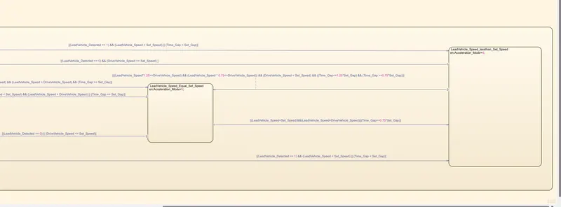
- LeadVehicle_Speed_lessthan_Set_Speed
- LeadVehicle_Speed_Equal_Set_Speed
i) LeadVehicle_Detected_Follow (Default):
- This is the default sub state inside ACC ON MODE state. Output signal Acceleration_Mode is equal to 2.
- Condition to transit from LeadVehicle_Detected_Follow to LeadVehicle_Not_Detected; Input signal condition LeadVehicle_Detected == 0.
- Condition to transit from LeadVehicle_Detected_Follow to LeadVehicle_Speed_lessthan_Set_Speed; Input Signals condition (LeadVehicle_Detected == 1) && (LeadVehicle_Speed < Set_Speed) || (Time_Gap < Set_Gap).
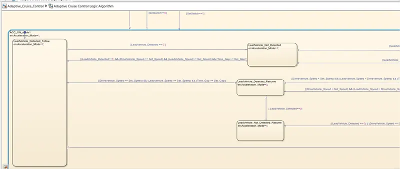
ii) LeadVehicle_Not_Detected:
- Output signal Acceleration_Mode is equal to 1.
- Condition to transit from LeadVehicle_Not_Detected to LeadVehicle_Detected_Follow; Input signals condition [(LeadVehicle_Detected==1) && (DriveVehicle_Speed == Set_Speed) && (LeadVehicle_Speed >= Set_Speed) && (Time_Gap >= Set_Gap)]
- Condition to transit from LeadVehicle_Not_Detected to LeadVehicle_Speed_lessthan_Set_Speed; Input signals condition [(LeadVehicle_Detected == 1) && (LeadVehicle_Speed < Set_Speed) || (Time_Gap < Set_Gap)]
iii) LeadVehicle_Detected_Resume:
- Output signal Acceleration_Mode is equal to 3.
- Condition to transit from LeadVehicle_Detected_Resume to LeadVehicle_Detected_Follow; Input signals condition [(DriveVehicle_Speed == Set_Speed) && (LeadVehicle_Speed >= Set_Speed) && (Time_Gap >= Set_Gap)]
- Condition to transit from LeadVehicle_Detected_Resume to LeadVehicle_Not_Detected_Resume; Input signal condition LeadVehicle_Detected==0.
- Condition to transit from LeadVehicle_Detected_Resume to LeadVehicle_Speed_equal_Set_Speed; Input Signal condition [(DriveVehicle_Speed < Set_Speed) && (LeadVehicle_Speed > DriveVehicle_Speed) && (Time_Gap >= Set_Gap)]
iv) LeadVehicle_Not_Detected_Resume:
- Output signal Acceleration_Mode is equal to 1.
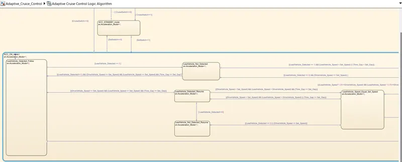
v) LeadVehicle_Speed_lessthan_Set_Speed:
- Output signal Acceleration_Mode is equal to 4.
- Condition to transit from LeadVehicle_Speed_lessthan_Set_Speed to LeadVehicle_Not_Detected; Input signal condition [(LeadVehicle_Detected == 0) && (DriveVehicle_Speed == Set_Speed)]
- Condition to transit from LeadVehicle_Speed_lessthan_Set_Speed to LeadVehicle_Speed_equal_Set_Speed; Input signals condition [((LeadVehicle_Speed*1.25>=DriveVehicle_Speed) && (LeadVehicle_Speed * 0.75<=DriveVehicle_Speed)) && (DriveVehicle_Speed < Set_Speed) && ((Time_Gap<=1.25*Set_Gap) && (Time_Gap >=0.75*Set_Gap))].
vi) LeadVehicle_Speed_Equal_Set_Speed:
- Output signal Acceleration_Mode is equal to 5.
- Condition to transit from LeadVehicle_Speed_equal_Set_Speed to LeadVehicle_Not_Detected_Resume; Input signal conditions is [(LeadVehicle_Detected == 0) || (DriveVehicle_Speed <= Set_Speed)]
- Condition to transit from LeadVehicle_Speed_equal_Set_Speed to LeadVehicle_Detected_Resume; Input signal conditions [(DriveVehicle_Speed < Set_Speed) && (LeadVehicle_Speed > DriveVehicle_Speed) || (Time_Gap >= Set_Gap)]
- Condition to transit from LeadVehicle_Speed_equal_Set_Speed to LeadVehicle_Speed_lessthan_Set_Speed; Input signals conditions [(LeadVehicle_Speed<Set_Speed)&&(LeadVehicle_Speed<DriveVehicle_Speed)||(Time_Gap==0.75*Set_Gap)].
Come to the top layer subsystem ADAS.
All signals need to be resolved at the origin.
Steps fro resolving signal: Right click on signal line>>pop-up window appear>> click on Properties at bottommost>>Signal Properties window appear>>Tick the checkbox that reads "Simulink signal must reslove to simulink signal object"
As we click on Apply, we find an "E" with middle line extended backward like symbol appear at starting of Signal label_name.
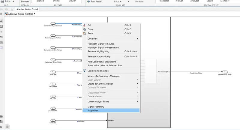
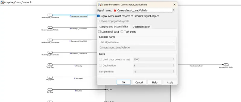
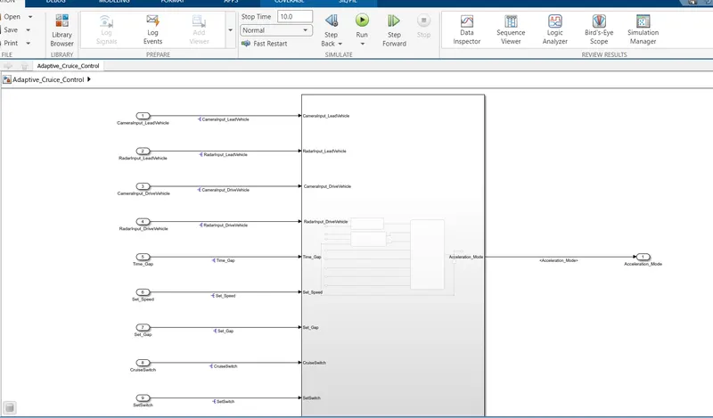
Resolve all the input signals at te top layer.
Do signal labelling and signal propagation wherever is required.
3. REQUIREMENT TAGGING:
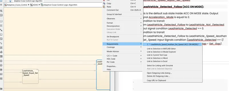
First of all create a requirement file, flie maybe word ,excel,MATLAB or in some other format.
Now open model window and make right click on top level subsystem.
It'll show a context menu, Select Requirements>>Link to selection in word.
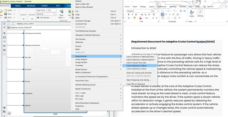
Now open inner level subsystems and do the same drill for each level of subsystem Requirment present in the model.
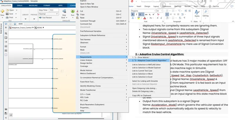
4. SLDD CREATION:
- Now it's time to create Data Dictionary to access all the input, output signal values and also the Calibration values.
- Steps to create Data Dictionary: Goto Model Properties >> External Data
- Select New, it'll ask for name.
- Name your Data Dictionary and uncheck the box present at the bottom which reads ''Enable model access to base workspace''.
- Press Apply and Ok.
- If Data Dictionary is Created succesfully, it'll start showing to Explore Data Dictionary at the bottom Left corner of the model window.
- Click on External Data showing at bottom left corner of model window, a new window of model porerties will going to open.
- Click on drop down arrow of Data Dictionary, Design Data appear
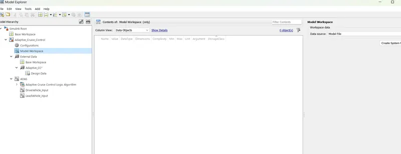
- We are ready to add all parameters of input ,output and calibration. Parameters like Initial value, Min and Max value, Dimension, DataType, Storage class, Unit can be set created a data dictionary.
- Add all the Signals and Calibration values which are given to us.
- Use Simulink Signal from the top icon tray to add input and output signals.
- Use Simulink Parameters from the top icon tray to add Calibration values
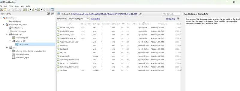
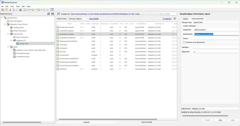
- The storage class for Input signals should be ImpotedExtern , for output signals: ExportToFile and for Calibration values: ConstVolatile.
- If choosing ExportToFile or ConstVolatile as storage class, we must have to provide HeaderFile and DefinitionFile as shown below.
- After addiing all values, go to list of files present at the left side ,find Data Dictionary, make right click on it, a context menu appear , select Save Changes.
5. SETTING CONFIGURATION PARAMETERS:
- To open Configuration Parameters: Goto model window>>Modelling>>Model Setting.
- Another shortcut way to open it, by pressing Ctrl+E.
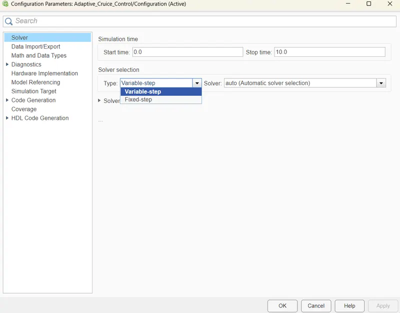
- First of all change Solver setting ,by default it is set to Automatic we need to change it to Discrete(No continuous states).
- Also change Solver Type to Fixed-step from Continuous step.
- Provide Fundamental sample time as '0.01'
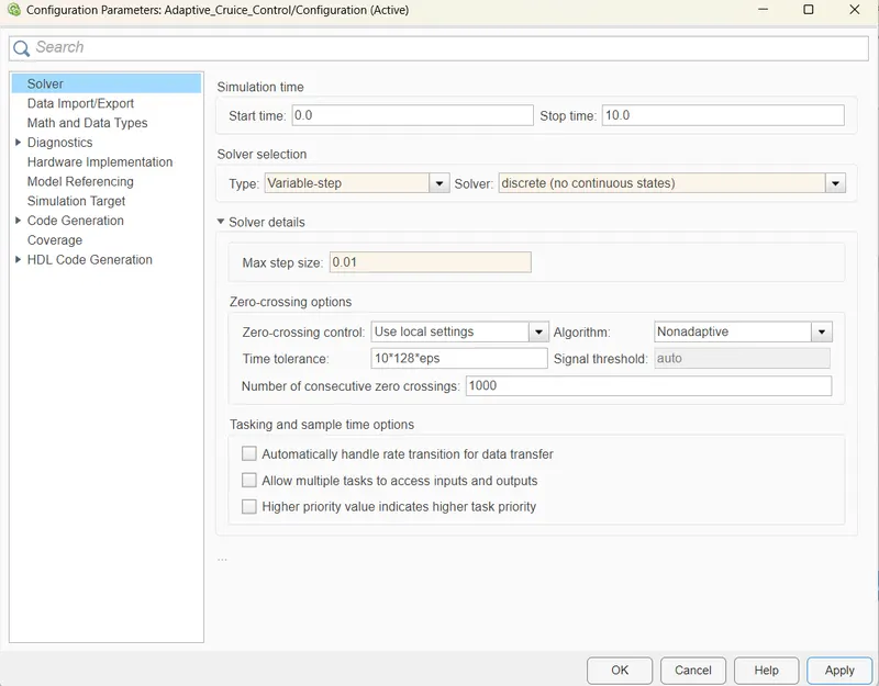
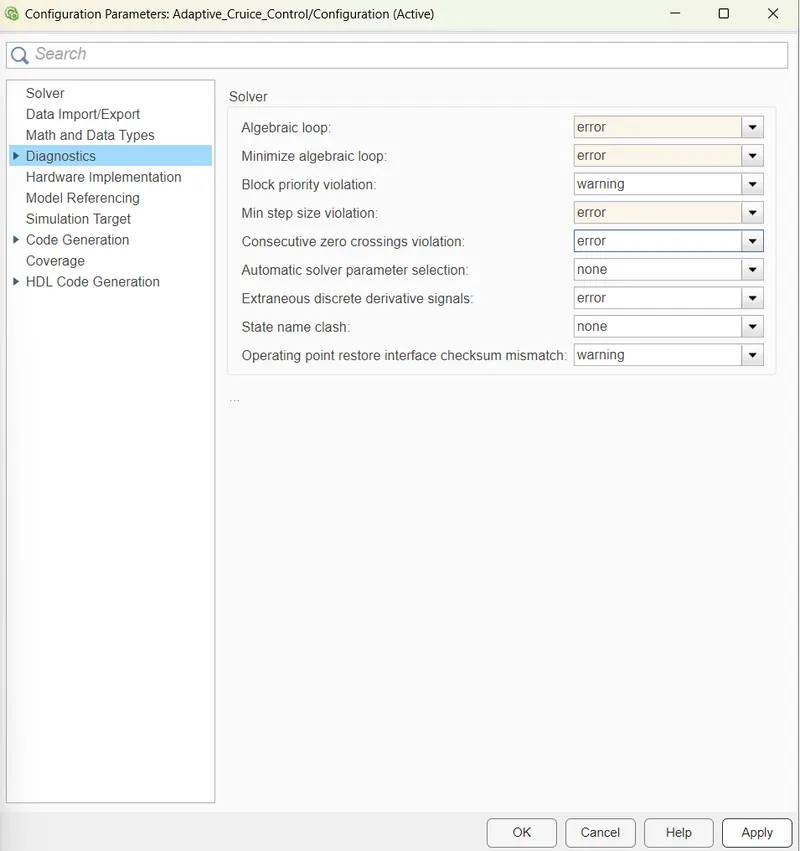
Making Some changes in Configuration Parameters in accordance with the MAAB Guidlines.
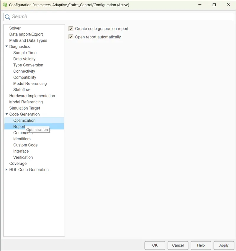
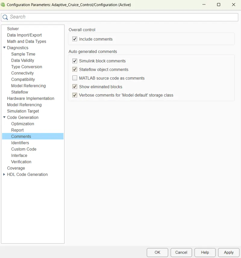
- Most Important change required for Code eneration.
- Goto Code Generation in Configuration Parameter.
- Change the System Target File from 'grt.tlc' to 'ert.tlc' Embedded Coder.
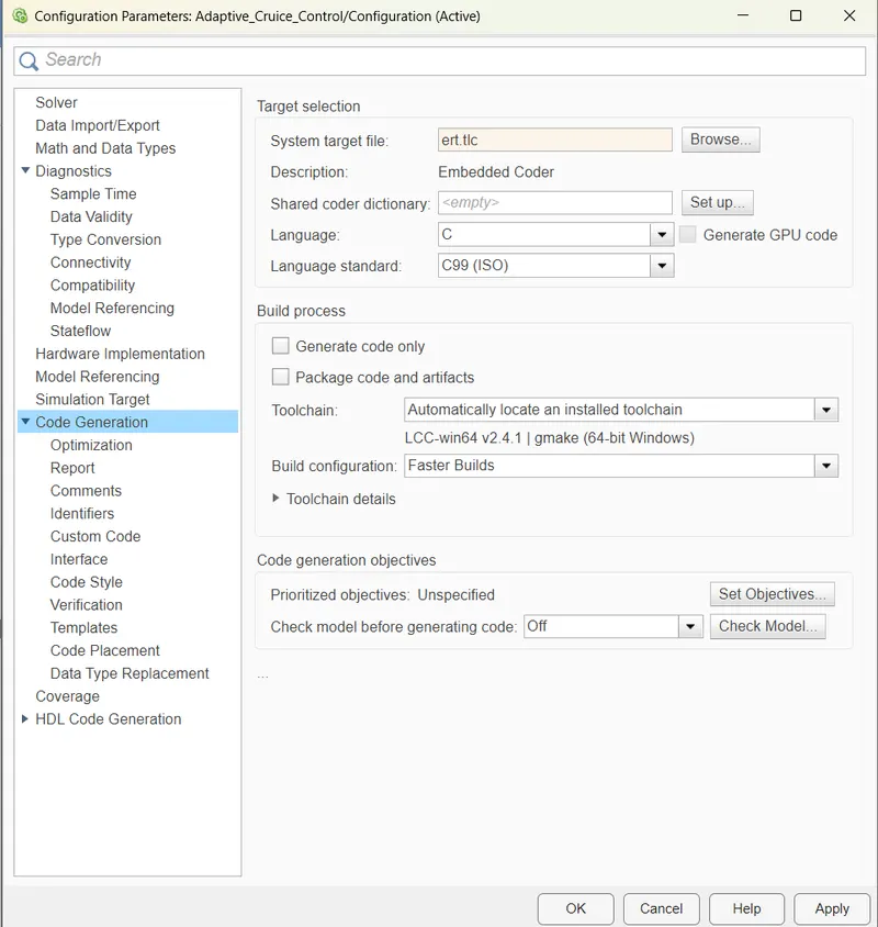
- It might be possible that we forget to set some values, for that sake we will do Model Advisor check and run.
6. MODEL ADVISOR REPORT:
- Now before going to Generate Code, Run Model Advisor and see its report what errors or warnings are encountering at this stage pertaining to modelling guidelines and standards.
- Try to diagnos those errors/ warnings.
- All the errors must be removed but some warnings maybe retained if not affecting any of the functionality.
- How to open Model Advisor: Goto Simulink Model window>> click on model advisor at the top left corner of window(a symbol of green right tick inscribed in a green circle).
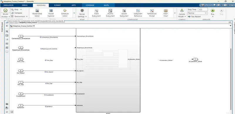
After clicking on Model Advisor a pop-up window of System Selector appear as shown in image below.
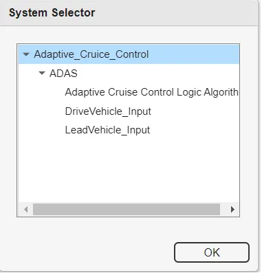
- Select System and click OK.
- A new window will open which consists of two major checkbox: By Product and By Task.
- Go with By Task, inside it there are too many checks pertaining to Modelling standard ,Guidelines.
- We need to tick on the checks for Modelling Standard for MISRA C:2012 , Modelling Standard for ISO 26262, Modelling Standard for MAAB, Modelling Standard for JMAAB.
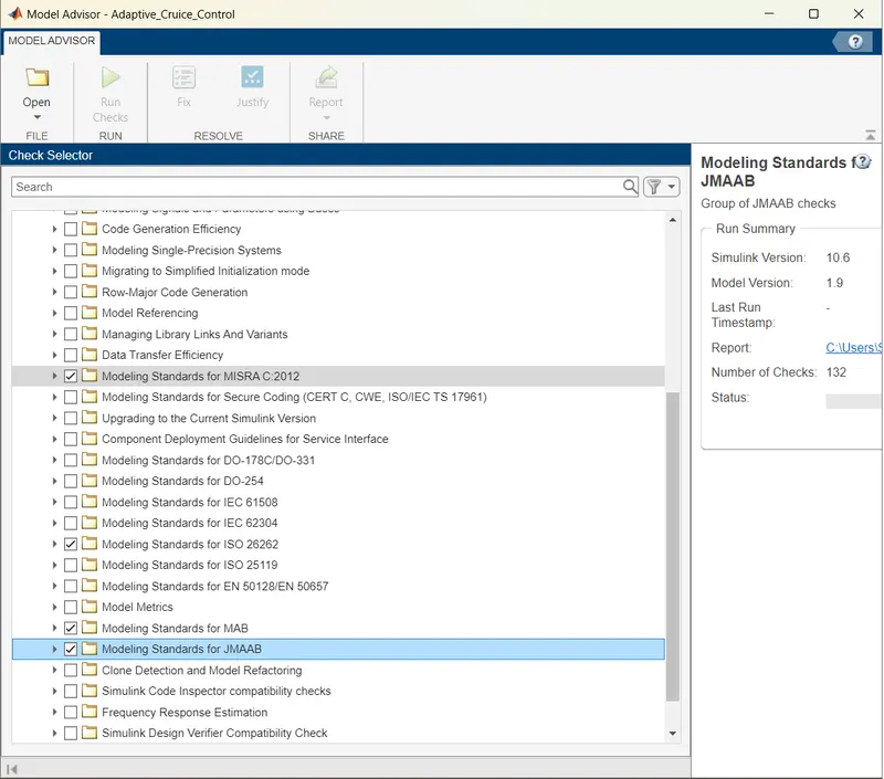
After marking on all the required checks,click on Run Selected Checks.
After Build a model for generating code
Results:
After implementing the ACC model run the simulation. If the model is running successfully without any errors then the Adaptive Cruise Control is works as per the requirement.
- The model is running successfully without any error.
Conclusion:
Hence, The Adaptive Cruise Control feature is developed as per the Requirement Document using MATLAB Simulink.