Project 2 Adaptive Cruise Control
Adaptive Cruise Control:
- Adaptive cruise control (ACC) is an active safety system that automatically controls the acceleration and braking of a vehicle. It is activated through a button on the steering wheel and cancelled by driver’s braking and/or another button
- By monitoring other vehicles and objects on the road, adaptive cruise control enables a safe and comfortable driving experience. It does so by helping the driver keep a steady vehicle speed at a given moment. The driver can set their preference regarding certain factors, such as the distance to the car in front, driving mode – for example, economical, sporty or comfortable – and others. Together with information about speed limits, road curvature, accidents data and more, these choices influence the automatically selected speed.
- Cruise control has come a long way from its early days in its quest to assist drivers on the road. When first introduced, it was only found in luxury car models due to its high production cost. As less expensive sensors reached the market, adaptive cruise control is steadily becoming a standard feature in new vehicles today.
To create a ACC algorithm ; ACC have 3 mode of operations.
- ACC ON mode
- ACC STANDBY
- ACC OFF mode
sldd file is created and assigned the 9 input signals and outputs signals using simulink signal
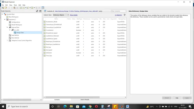
Before developing ACC algorithm we need to develop Lead vehicle and Drive vehicle
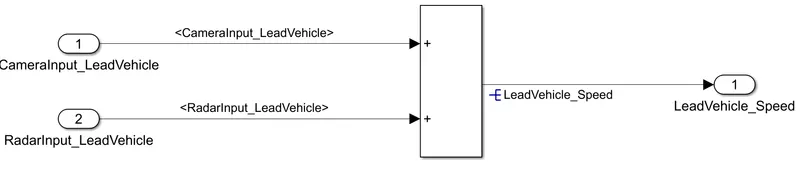
- Lead Vehicle:Lead Vehicle is a vehicle which is driving in the road ahead of our drive vehicle.
For this lead vehicle we have 2 input signals;(Signal Name: CameraInput_LeadVehicle & RadarInput_LeadVehicle)
And the output of this is lead vehicle speed as shown below
Drive vehicle:
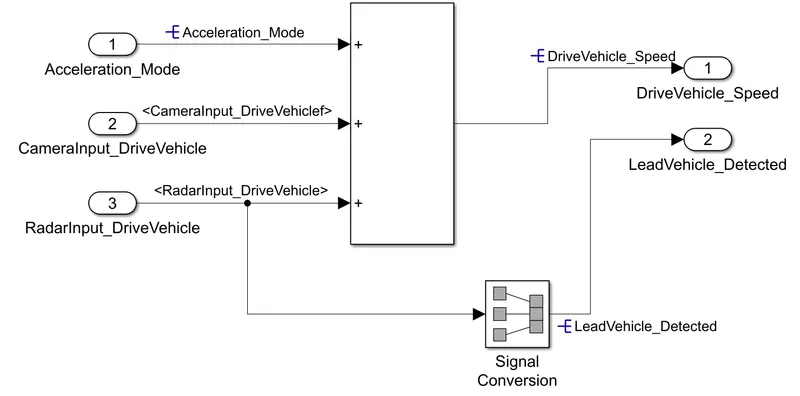
- Drive Vehicle is the vehicle driven by the user & this is the vehicle which has ACC algorithm in it.
The input signal for this is Accelaration mode,Camera input ,radar input and the output is drive vehicle speed and lead vehicle detected as shown below.
ACC model (3 subsystems):
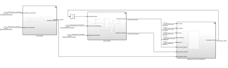
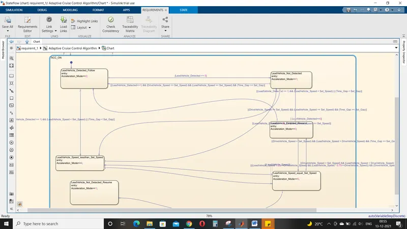
Inside the subsystem 3 we developed a state flow logic for ACC system.For this logic we have total 8signals including outputs from lead vehicle and drive vehicle.And the output of this ACC system will be the accelaration mode.Based on the speed , road condition , lead vehicle behaviour.
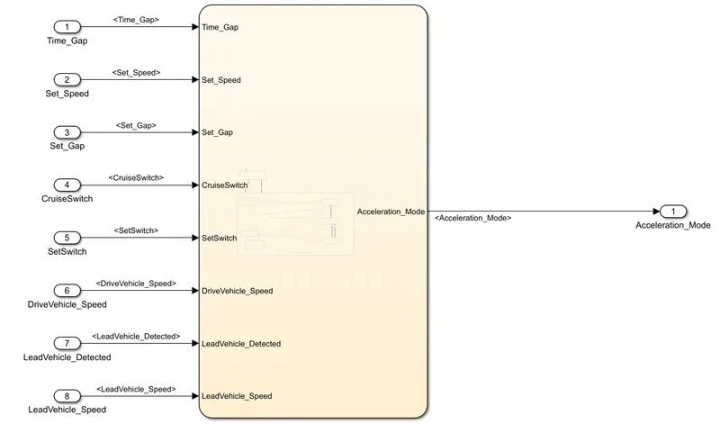
To make the this system understand and to allow to monitor and control, we need to implement the logic /condition for safe driving experience For this we have 3 mode of operations as discussed earlier.
ACC OFF mode:
This state is governed by input signal CruiseSwitch.If CruiseSwitch is equal to 1, state ACC STANDBY mode will get activated. If CruiseSwitch is equal to 0, state ACC OFF mode will get activated, from either ACC ON mode or ACC STANDBY mode
At this stage Accelaration mode will be '0'
ACC STANDBY MODE :
This is the second activated state inside state machine logic.This state is governed by both input signals CruiseSwitch & SetSwitch.If CruiseSwitch is equal to 1, state ACC STANDBY mode will get activated. If CruiseSwitch is equal to 0, state ACC OFF mode will get activated, from either ACC ON mode or ACC STANDBY mode If SetSwitch is equal to 1, state ACC ON mode will get activated. If SetSwitch is equal to 0, state ACC STANDBY mode will get activated.
Output signal Acceleration_Mode is at value 1 in this state
ACC ON MODE :
This state will be activated when input signal SetSwitch is equal to 1. There are 6 sub states to this state logic: They are:
- LeadVehicle_Detected_Follow (Default)
- LeadVehicle_Not_Detected
- LeadVehicle_Detected_Resume
- LeadVehicle_Not_Detected_Resume
- LeadVehicle_Speed_lessthan_Set_Speed
- LeadVehicle_Speed_equal_Set_Speed
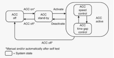
The state logic is developed with the above system as a reference
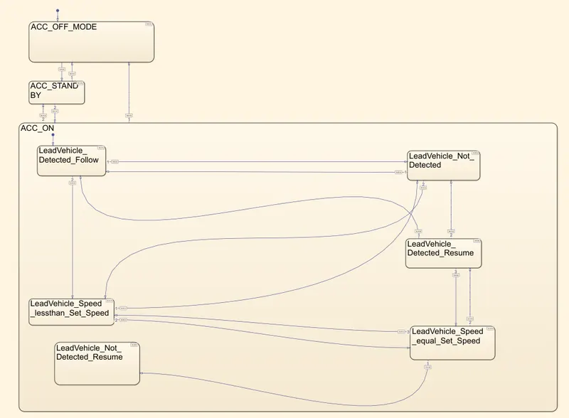
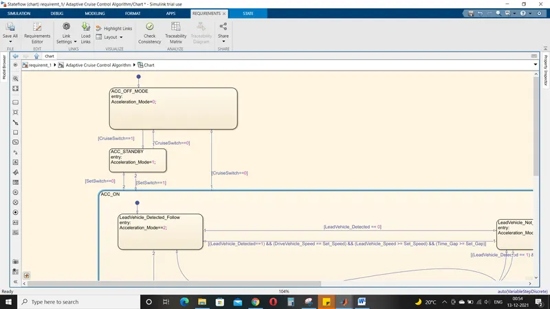
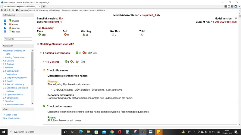
After simulating the model; and before generating the code we need to check for model performance for any errors or mismatch or any connections left open.This model advisory helps us to understand the errors or failure or warning developed in the model ; it overall checks the performance of the model.
Model Advisory:
Model Advisor is a tool that automatically checks the models for errors using pre-defined checks.
As fas as checks are concerned , most of the checks are pre-defined which are embedded into the MATLAB environment directly,though few other checks can be loaded into the tool as well-option to customize and add the checks are there as well.
Model Advisor Procedure:
Model Advisor ->select for subsystem or model to check the performance ->click ok
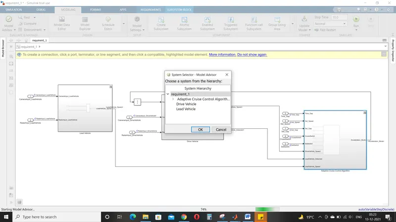
In model Advisor we have 2 systems
- By product : This part deals with the settings
- By Task: By task deals with the MAAB guidlines
After selecting the required parameters we can run the test ; by clicking on 'run selected objects' and also can generate the report by enabling the option below to it
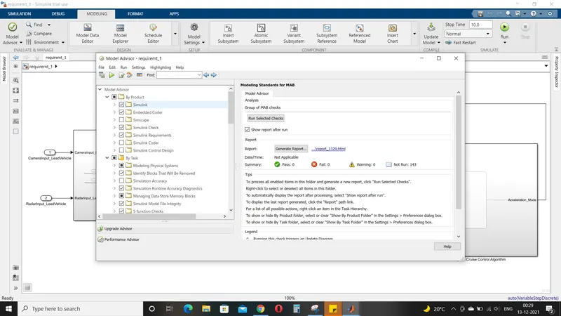
It will display the pass , fail, warning objects in the report.
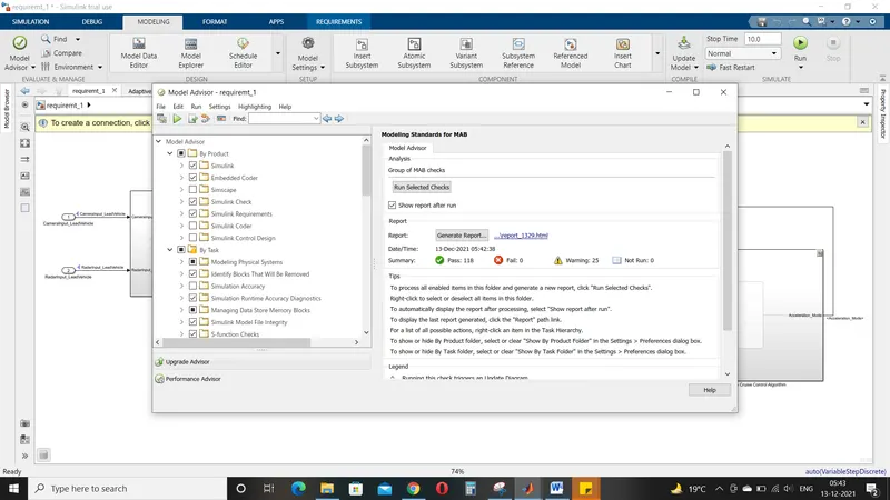
The below is the generated report of the file 'Requirement -1 '
And there is no fail objects; if fails objects occurs simulation cannot be done.
Warnings can be corrected for better performance.
Requirement Tagging:
Requirement tagging is done for all the 3 subsystems. To tag 3 subsystema and generate tracebility report we need to create a word file and add the 3 requirements as shown below.

Now right click on the subsystem and click on the link to selection in word
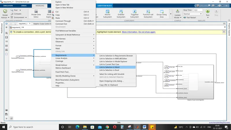
The below image represents the taggingg of the subsystem
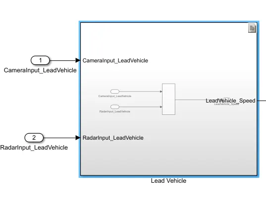
Tagging requirement of Lead vehicle:
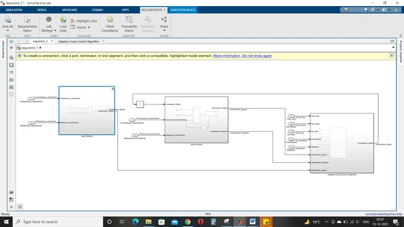
In the same way requirement tagging is done for other 2 subsystems.
Tagging requirement report of Lead vehicle:
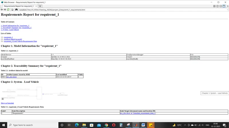
Tagging requirement of Drive vehicle:
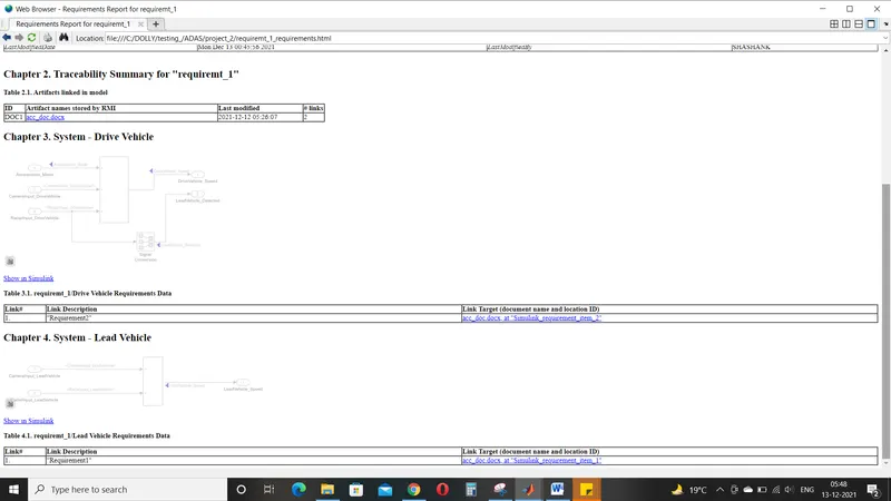
Tagging requirement report of state flow logic (ACC Algorithm):
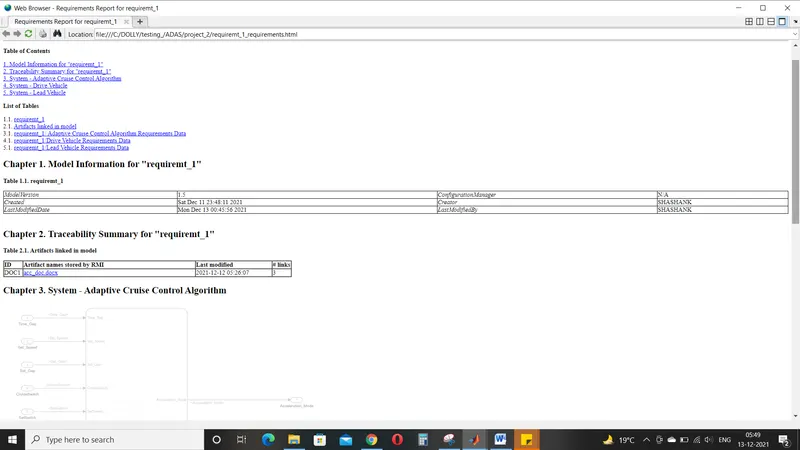
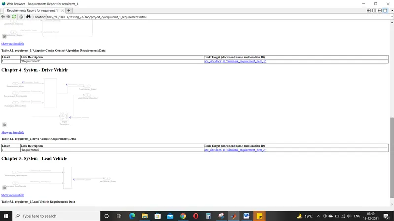
Code Generation:
For code generation we need to enable the setting ans formats in the configuration parameters.
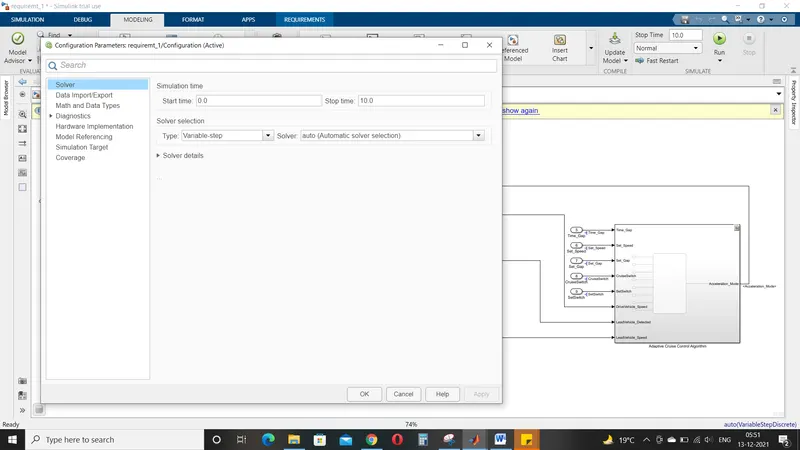
Due to software issue unable to generate the code and enable the settings as per the requirements.
Signal reslolving and propogating:
In our model we have done signal resolving and propugating .It is done because we have assigned values in sldd file.To read those values /variable in the simulink we need to resolve the signal either input/output.
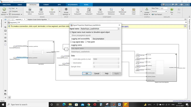
And signal propoguting is done inside the subsystem input.Outside the subsystem input we have to resolve but inside we need to propogate it.We cannot resolve the same input twice.
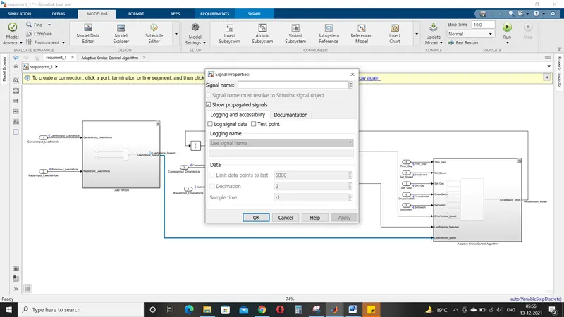
Signal resolving and propogating need to be done whenever a sldd variables are assigned for simulink model.