Project 2 Adaptive Cruise Control
Aim: To develop an MBD-compliant Adaptive Cruise Control feature as per the provided requirement document using MATLAB Simulink
Objective of Main Project:
- Developing Adaptive Cruise Control feature as per the Requirement Document using MATLAB Simulink.
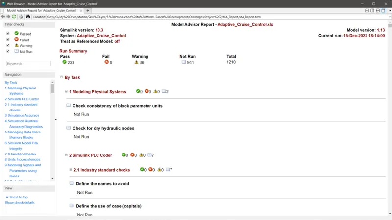
- Follow all the MBD related processes: Requirement Tagging & Traceability, SLDD creation, Configuration Parameter changes, Model Advisor check & Code Generation.
- In Configuration Parameters: enable “Support Floating Numbers” under Code Generation settings.
- Use Embedded Coder to generate the code.
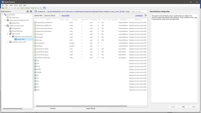
- If choosing code generation, Storage class for Input signals: ImportedExtern; Storage class for Output signal: Export to File; Storage class for local signals: localizable; Storage class for calibration signals: Const.
- Choose sample time for all signals as 0.01s
Model:
The base model consists of 9 inputs and 4 outputs as given in the requirement:
Signals & Calibration Data List:
|
SL.no |
Signal / Calibration Name |
Signal Type |
Data Type |
Dimension |
Min |
Max |
Initial Value |
Units |
|
1. |
CameraInput_LeadVehicle |
Input |
Uint8 |
1 |
0 |
255 |
- |
- |
|
2. |
RadarInput_LeadVehicle |
Input |
Uint8 |
1 |
0 |
255 |
- |
- |
|
3. |
CameraInput_DriveVehicle |
Input |
Uint8 |
1 |
0 |
255 |
- |
- |
|
4. |
RadarInput_DriveVehicle |
Input |
Uint8 |
1 |
0 |
255 |
- |
- |
|
5. |
Time_Gap |
Input |
Uint8 |
1 |
0 |
255 |
- |
- |
|
6. |
Set_Speed |
Input |
Uint8 |
1 |
0 |
255 |
- |
- |
|
7. |
Set_Gap |
Input |
Uint8 |
1 |
0 |
255 |
- |
- |
|
8. |
CruiseSwitch |
Input |
Boolean |
1 |
0 |
1 |
- |
- |
|
9. |
SetSwitch |
Input |
Boolean |
1 |
0 |
1 |
- |
- |
|
10. |
Acceleration_Mode |
Output |
Uint8 |
1 |
0 |
255 |
- |
- |
|
11. |
LeadVehicle_Speed |
Output |
Uint8 |
1 |
0 |
255 |
- |
- |
|
12. |
DriveVehicle_Speed |
Output |
Uint8 |
1 |
0 |
255 |
- |
- |
|
13. |
LeadVehicle_Detected |
Output |
Uint8 |
1 |
0 |
255 |
- |
- |
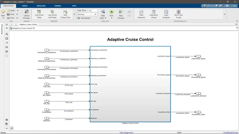
Inside the Adaptive Cruise Control Subsystem, We have created 3 subsystems for the 3 main requirements.
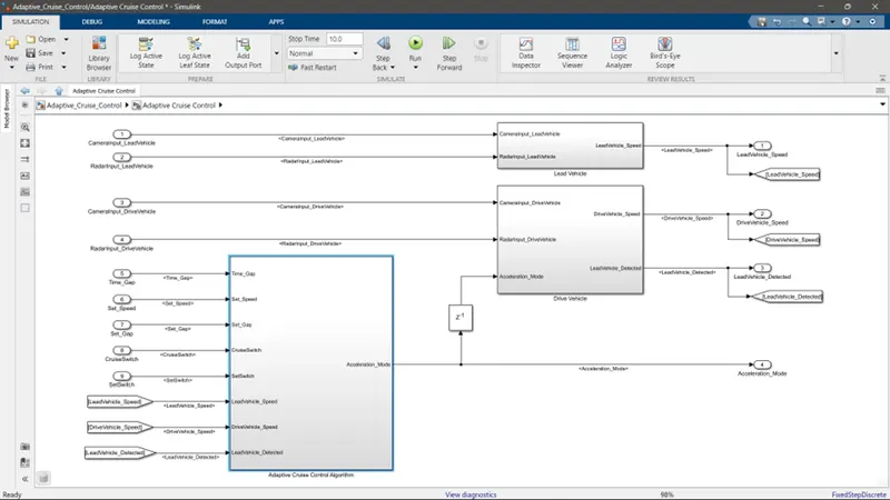
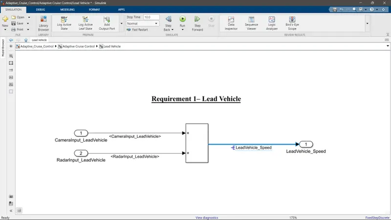
Requirement 1: Lead Vehicle is designed inside the Lead Vehicle Subsystem
The radar & camera inputs are added to get the Lead Vehicle Speed Output.
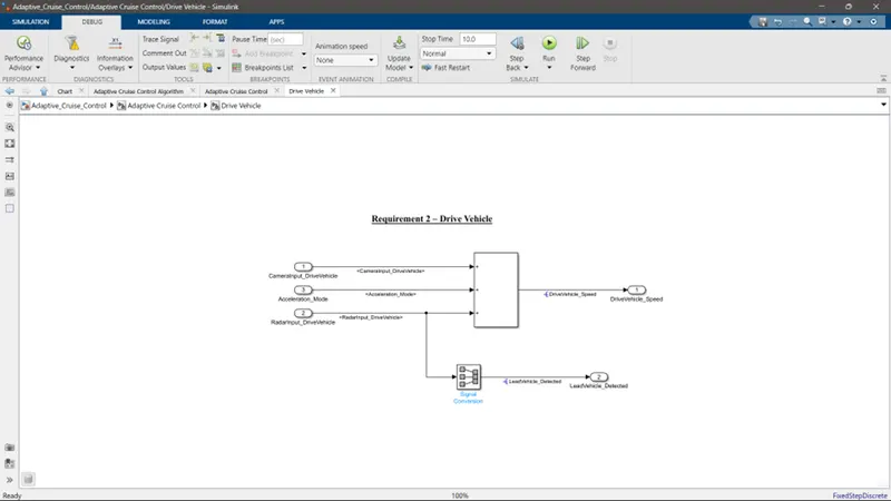
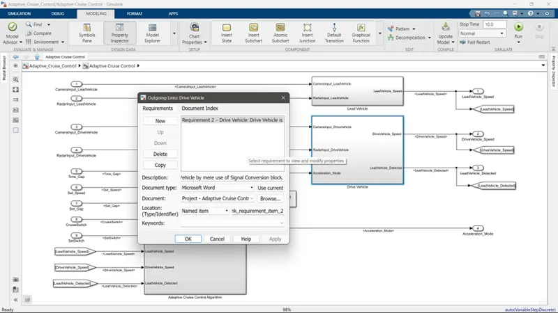
Requirement 2: Drive Vehicle is designed inside the Drive Vehicle Subsystem
The radar & camera inputs & Acceleration mode are added to get the Drive Vehicle Speed Output.
And the radar input is passed through a Signal Conversion block to get LeadVehicle_Detected.
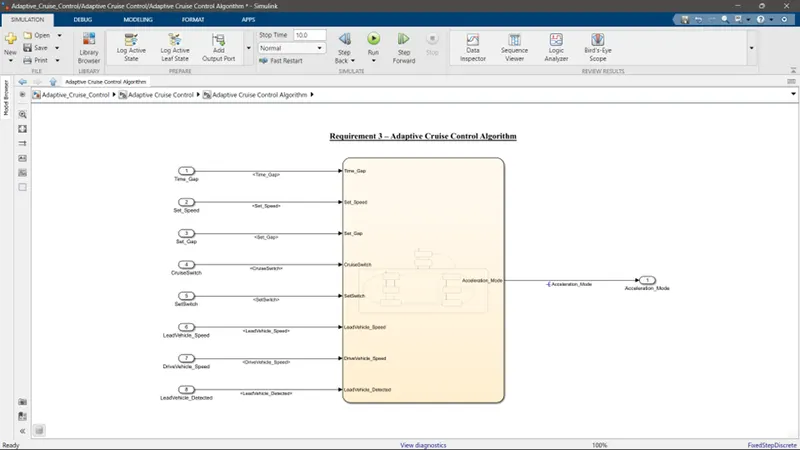
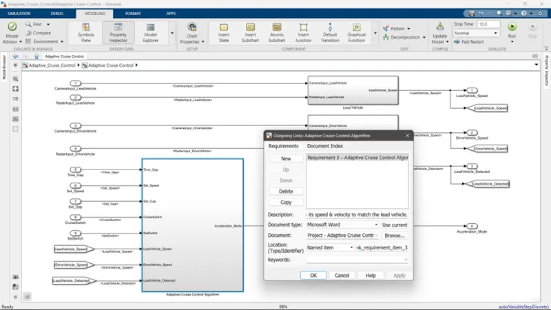
Requirement 3: Adaptive Cruise Control Algorithm is deigned with state machine logic. The inputs of this are the rest of the unused inputs and the outputs of the req 1 & 2, And the output of it is the Acceleration Mode.
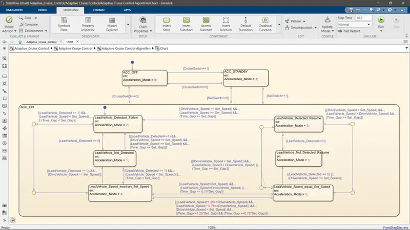
Inside the Sate Machine Chart, the main states are ACC_ON, ACC_OFF and ACC_STANDBY. These are deigned by the logic given in the requirement description itself.
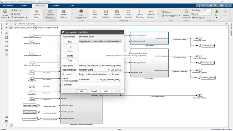
Requirement Tagging:
SLDD File:
MODEL ADVISOR Check:
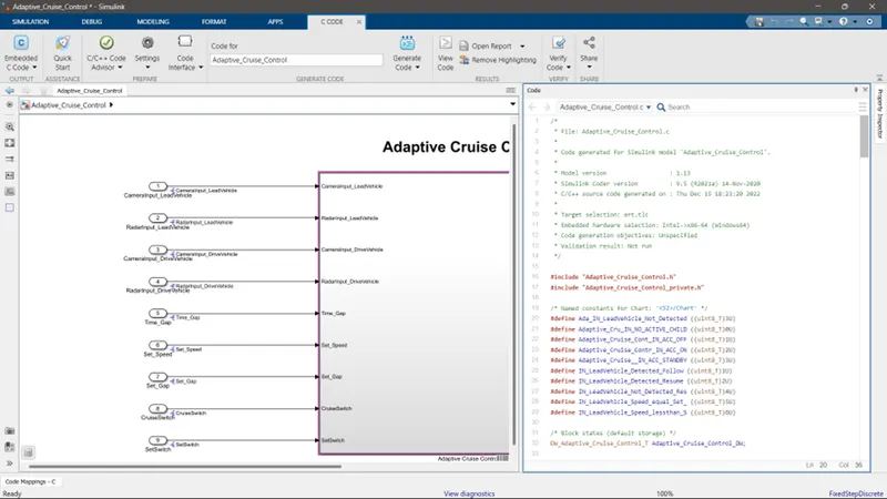
Code Generated using Embedded Coder: