Project 2 Adaptive Cruise Control
PROJECT ON
Adaptive Cruise Control
Aim:To Develop Adaptive Cruise Control Model as per the Requirement Document using MATLAB Simulink.
Introduction:Adaptive cruise control (ACC) is an advanced driver assistance system for road vehicles that automatically adjusts the vehicle speed to maintain a safe distance from vehicles ahead. This is also known as Dynamic Curuise Control. The Control is based on various sensor information from onboard sensors which is mounted inside the Vehicle. Such system uses radar/laser sensors or Camera which allow the vehicle to break when it detects the Vehicle is approaching another vehicle ahead. ACC technology is going to be the key component of upcoming Generation Vehicle. This technology enhances the passengers safety and also increase road capacity by maintaning seperation between Vehicles. ACC doesnot provide full autonomy, the system only provides some help to the deiver but doesnot drive the car itself.
A radar sensor is usually at the core of the Adaptive Cruise Control. Installed at the front of the vehicle, the system permanently monitors the road ahead. As long as the road ahead is clear, cruise control feature maintains the speed set by the driver. If the system spots a slower vehicle within its detection range, it gently reduces speed by releasing the accelerator or actively engaging the brake control system. If the vehicle ahead speeds up or changes lanes, the cruise control automatically accelerates to the driver’s desired speed.
Since Adaptive Cruise Control is a comfort and convenience system, brake interventions and vehicle acceleration only take place within defined limits. Even with Adaptive Cruise Control switched on, it remains the driver’s responsibility to monitor the speed and distance from the vehicle in front.
>The Steps to Create the project are as below:
1.Understand the Requirement clearly.
2.Take the Sub_System block to represent the each requirement. The number of Sub_System must be equal to the number of requiremnt.
3.Develop the Simulink model as per the Requirements in each Sub_System.
4.Create the SLDD as per the given Data & link it to the model. If note given we have to create SLDD based on our understanding of the Requirements.
perform the signal resloving inorder to avoid any data losses.
5.Configuration Setting for Solver as per the Simulink Model and Code Generation if we want code.(We also make coverage setting if we want coverage report).
6.Do the Requirement Tagging to Sub_System.
before taking model advisory report run the simulink once to check is there is any error or warning.
7.Now Tke Model Advisory Report selecting MAB.
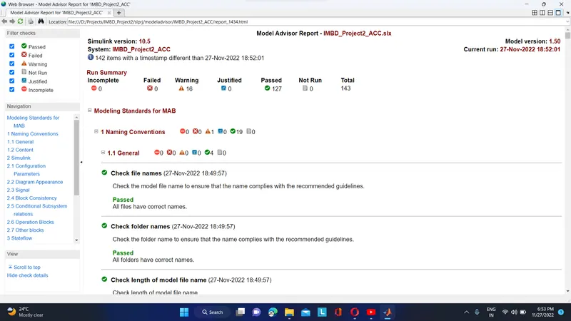
Note in Model Advisory Report the failure case should be 0, and warning should me minimum(nearly 10)
Then go for code generation use Embedded coder using App tab in the top row of simulink window.
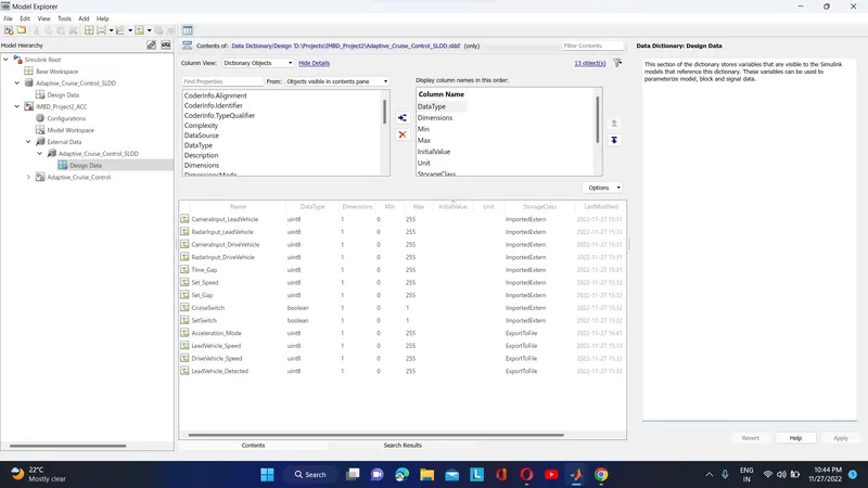
>The Figure below shows the SLDD crated for the model.
The Simulink Model is developed as per the requirement 1, 2 and 3.
Since there is 3 requirement we required 3 sub_system to develop the model.
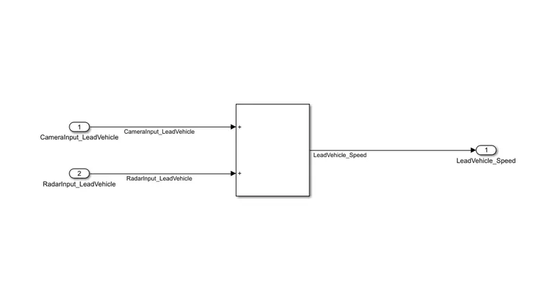
>As per the Requirement1-Lead Vehicle, we have to take two input singal CameraInput_LeadVehicle and RadarInput_LeadVehicle respectively which is feeded into Add block.The out from the Add block is LeadVehicle_Speed.
The output from this subSystem is given as input to the Requirement3_Adaptive Curse Control subsystem block.Teh figure below shows the Simulink model for the Requirement1.
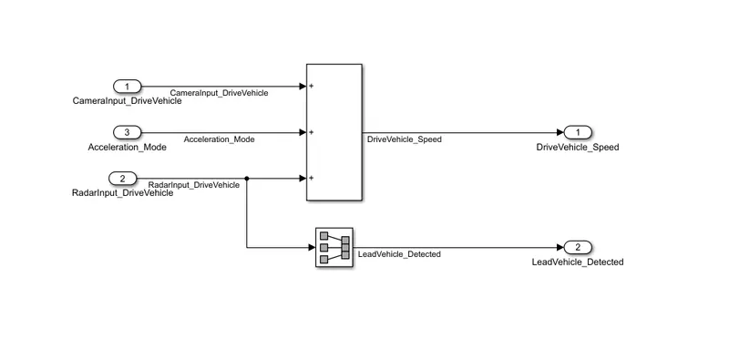
>As per the Requirement2-Drive Vehicle, we have 3 input signals CameraInput_DriveVehicle, RadarInput_DriveVehicle and Acceleration_Mode, in this model the three input is feeded into the Add block. There are two output from this subsystem one is from the Add block name as DriveVehicle_Speed and another is from the Signal conversion block name as LeadVehicle_Detected. The input to the signal conversion block is RadarInput_DirveVehicle.The figure below shows the simulink Model.
The output from this subsystem is feeded as input to the Adaptive Cruise Control subsystem block.
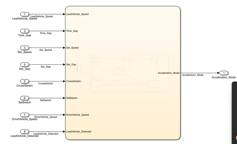
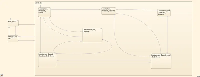
>Requirement3-Adaptive Cruise Contro Alglorithm, This subsystem block has three modes of operation OFF MODE, STANDBY MODE and ON MODE. This subsystem is implemented by State machine logic in Simulink.
There are 8 inputs to thise subsysem three from the 1st and 2nd sunsystem and the five inputs signals are Time Gap, Set Speed, Set Gap, CruiseSwitch and SetSwitch.The output signal from this subsystem is Acceleration_Mode.
The below figure show the simulink Model for this requirement subsystem.
The below figure shows inside chart model.
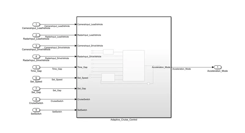
>The complete simulink model is as shown below. All the three subsystem is sumbersed in single SubSystem.
The below figure shows the output. Here all input signal block is replaced my constant block and Dispaly is cnnected at output side.
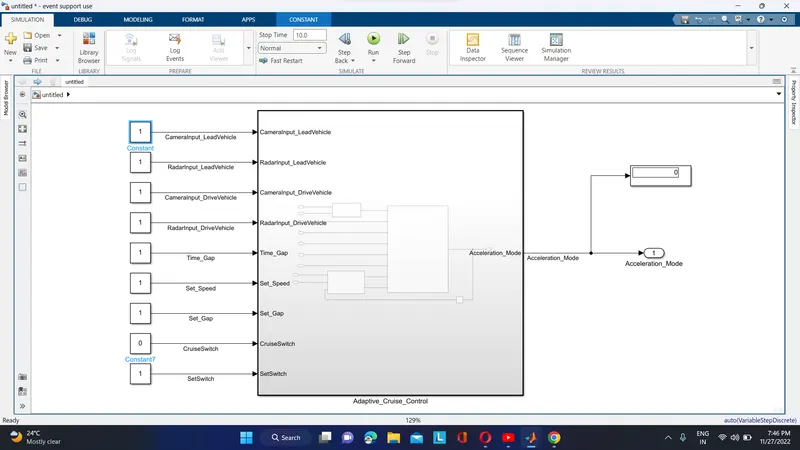
Here the 1st and 2nd constant block is feeded as input to the 1st subsystem(LeadVehicle) where this input signal get added and output(result after addition=2) is feeded as input to the subsystem3.
The 3rd and 4th constant block is feeded as input to the 2nd subsystem(DriveVehicle). the 3rd input to this subsystem is the feed back signal taken from the output with unit delay. All three signal get added and output(result after addition=2+x,since initial output condition is not specified) is connected to 3rd sunsystem.
Remaining input signal is also replaced by constant block with value 1 except constant block 7. constant block7 value is set to 0.
since the CruiseSwitch=0.The Acceleration_mode=0,which is displayed in dispaly block. thise is because there is no Transition in State Machine model i.e its remains in ACC_OFF_State.
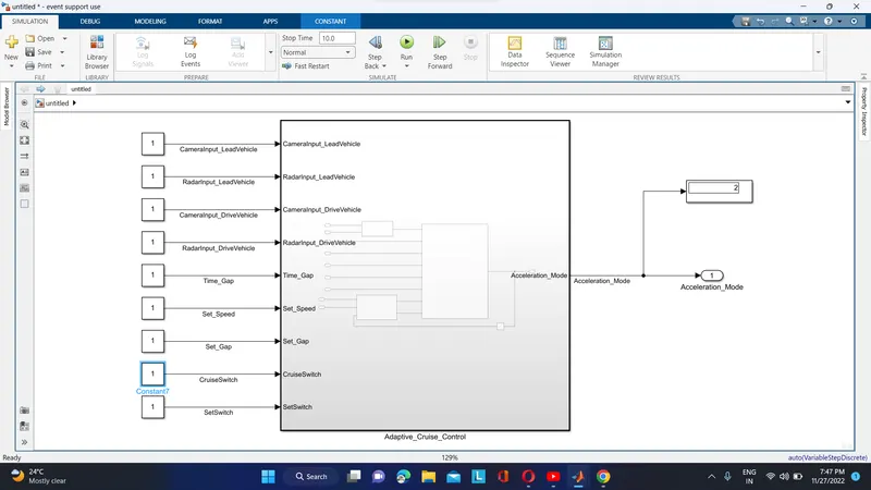
Here since the both the Switch signal is 1 thre is transition from ACC-OFF state to ACCSTANDBY state and then from ACCSTANDBY mode to ONSTATE. The Leadvehicle_Detection_Follow is the defult state for ACCON state. The output in display is 2, i.e Acceleration_Mode=2, which is defult state output assigned value. its mean all the Transiton Conditon in this state is false so the output is displayed from the defult state.
Note if any of the transition condition inside the square bracket becomes true there will be an transition and output results changes.
Step to create SLDD
1.Select MODELING tab, which is in the top row of the Simulink window.
2.Click on File.
3.Select New.
4.Click on Data Dictionary.
Now add the signal i.e input, otput, Constant as per the model by clicking on Add option at the top or simply cliking on shortcut availabe in 2nd row.
For input signal storage class is EmportedExtern.
For Output signal storage class is ExportToFile.
After this save it and link it to the model.
>The Figure below shows the SLDD crated for the model.
>Model_Advisor_Report.
Step To Take Model Advisor Report:-
1.Select Modeling in tab at top row of simulink model.
2.Click on Model Advisor select Model Advisor
3.The new window appears click on ok.
4.The Model Advisor window get apper.
5.Uncheck all the box if any.
6.Select MAB (MathWorks Advisory Board).
7.click on RUN checks.
The figure below shows the Model Advisor Report:
>Code_Generation
Step to Generate Code:-
For code generation we have to do configuration setting.
1.Select Modeling in tab.
2.Goto Model Settings select Model Settings.(we do it with shortcut key Ctrl+E)
3.Goto Code Generation and set the system target file as ert.tlc Embedded Coder.
4.After this go to App and select Embedded coder.
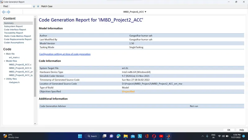
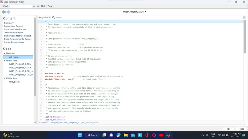
5.select or click on Generate Code.