Project 1 (Mini Project on Vehicle Direction Detection
Mini Project
Title
Vehicle Direction Detection
Aim:- To developed a simulink model, Which detect/detrmines the number of direction available in the Road for the Automobiles/Vehicle and dispaly it to the driver.
Introduction:-Identifying the direction of the vehicle is one of the important & diverse features in Autonomous driving & Advanced Driver Assistance Features. In this Project the inputs to the model are the steering wheel yawdegree and Camera signals. Depending on this two inputs the model determines the number of direction availabe for driver (i.e left , right or straight).
The Simulink model is developed as per the given Requirement 1 and 2.
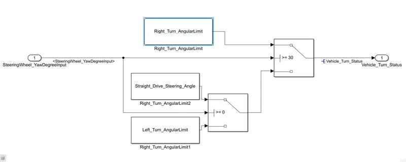
>In Requirement one we have to take one input from the steering wheel and compered it with the three angular values, i.e Right Turn, Left Turn & Straight Drive using a Switch block. The output from this Requirement one is local signal.The figure1 below shows the Simulink model as per the Requirement Data. The name of block are given as per the Requirement1
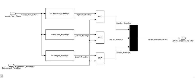
>In Reqquirement two we have to take two input one input is the otput from the requirement1 and other is Camera Signal input. This inputs are compared with three calibration values i.e Right Turn, Left Turn & Straight using logical operator block. The final output is only one among the three calibration signal. The figure2 below shows the Simulink model for as per the Requirement2.Here also the block name are given as per the Requiremnt2.
>The Steps to Create the project are as below:
1.Understand the Requirement clearly.
2.Take the Sub_System block to represent the each requirement. The number of Sub_System must be equal to the number of requiremnt.
3.Develop the Simulink model as per the Requirements in each Sub_System.
4.Create the SLDD as per the given Data & link it to the model. If note given we have to create SLDD based on our understanding of the Requirements.
perform the signal resloving inorder to avoid any data losses.
5.Configuration Setting for Solver as per the Simulink Model and Code Generation if we want code.(We also make coverage setting if we want coverage report).
6.Do the Requirement Tagging to Sub_System.
before taking model advisory report run the simulink once to check is there is any error or warning.
7.Now Tke Model Advisory Report selecting MAB.
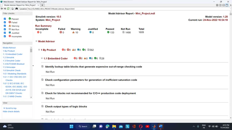
Note in Model Advisory Report the failure case should be 0, and warning should me minimum(nearly 10)
Then go for code generation use Embedded coder using App tab in the top row of simulink window.
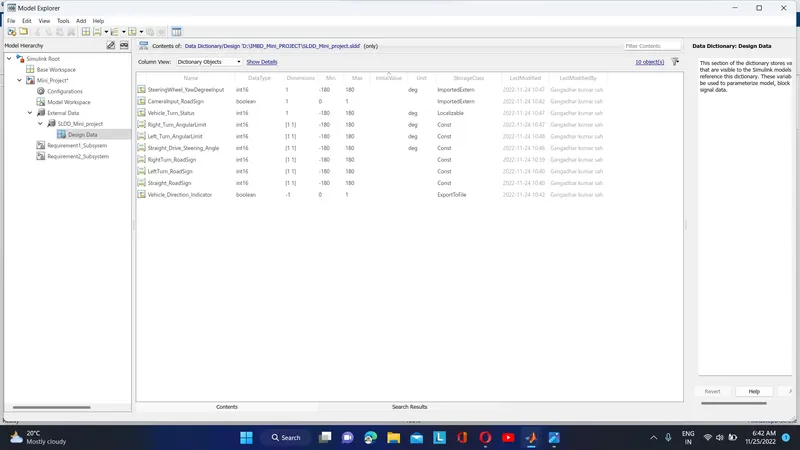
>The Figure below shows the SLDD crated for the model.
Step to create SLDD
1.Select MODELING tab, which is in the top row of the Simulink window.
2.Click on File.
3.Select New.
4.Click on Data Dictionary.
Now add the signal i.e input, otput, Constant as per the model by clicking on Add option at the top or simply cliking on shortcut availabe in 2nd row.
After this save it and link it to the model.
>The Simulink Model for this project is shown below.
Here the constant block is added in palce of Steeringwheel yawdegree input and Camerainput_Roadsign to test the model and dispaly is connected at output.
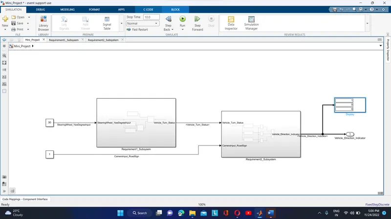
As we Observe in display the output shown is 1, 0, 0
Here the steeging wheel yawdegree is 30, which is compared aginst all three angular values inside the Requirement1_SubSystem. As the input is 30, which is >=30 the switch block pass the Right_Turn_AngularLimit valus as output(Vehicle_Turn_Status).
now the input for Requirement2 SubSystem block are Camerainput_Roadsign(which value is set to 1) and output from the Requirement1 block. The Vehicle_Turn_Status is compered with three Calibration values , after comparision output is AND with Camera input. The input Vehicle_Turn_Status is true for RightTurn_Roadsign and this get and with camera input and produce output high which is feeded into mux block the mux block takes 3 inputs and produce a output. sice in this case RightTurn_Roadsign is true and other condition are false the model dispaly the 1,0,0.
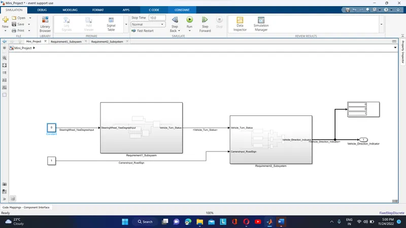
when the steegingwheel yawdegree input is set to 0 then the output should be 0,0,1. as shown below
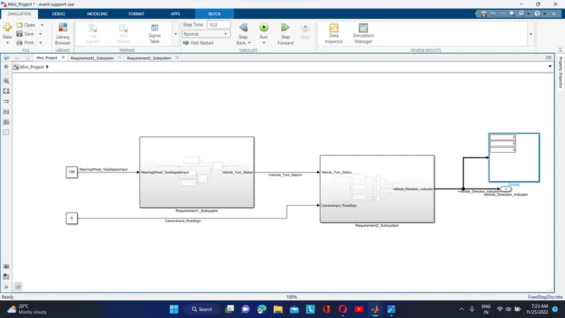
When the camera input is 0 then output is going to be 0, 0, 0. since AND gate output is only high if all the input condition are high.
>Model Advisory Report
Steps to take it
1.Select Modeling in tab at top row of simulink model.
2.Click on Model Advisor select Model Advisor
3.The new window appears click on ok.
4.The Model Advisor window get apper.
5.Uncheck all the box if any.
6.Select MAB (MathWorks Advisory Board).
7.click on RUN checks.
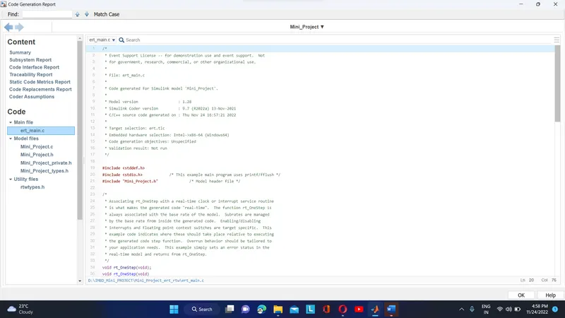
>Code_Generation
Steps
For code generation we have to do configuration setting.
1.Select Modeling in tab.
2.Goto Model Settings select Model Settings.(we do it with shortcut key Ctrl+E)
3.Goto Code Generation and set the system target file as ert.tlc Embedded Coder.
4.After this go to App and select Embedded coder.
5.select or click on Generate Code
wait for few seconds the code will automatic generated.